CHECK LIST
Group assignment
- do your lab's safety training test runout, alignment, speeds, feeds, materials, and toolpaths for your machine
WHAT MATERIALS CAN BE WORKED ON A CNC ROUTER MACHINE?
A CNC Router is a machine tool also known as a milling machine that is used to perform cutting and engraving on a very wide variety of metallic and non-metallic materials.
Among the most popular materials to cut and engrave with a CNC router we find:- Wood, MDF and Triplay
- Acrylic, Plexiglas and other plastics
- Aluminum, brass and other metals
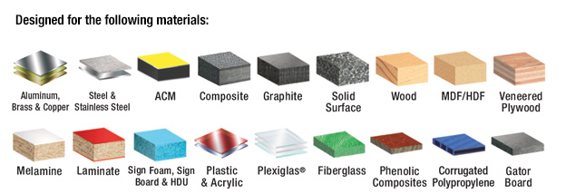
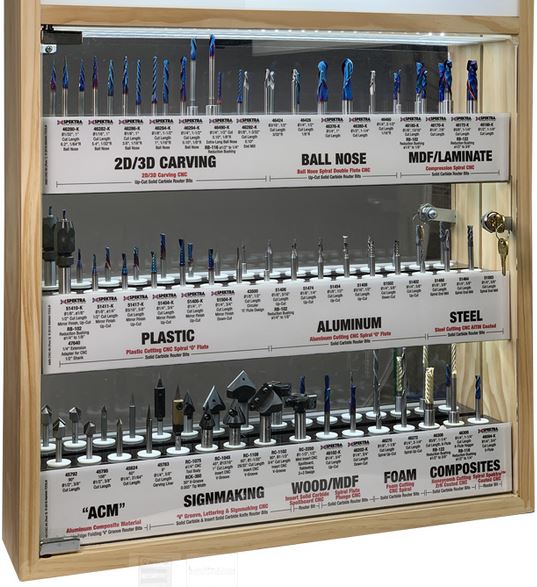
Of course, to be able to make all these cuts on these materials we need special tools for each of them
SAFETY RULES
During machining, keep your hands away from the rotating or moving tool. Even when the cutters are stopped they are cutting tools. When releasing or tying parts, precautions should be taken against cuts that can occur to the hands and arms.
Consider the following recommendations
- The switches and other machine start-up controls must be secured so that they are not accidentally actuated; involuntary starts have caused many accidents.
- Gears, drive belts, pulleys, gimbals and even protruding smooth shafts must be protected by covers
- Connect the equipment to electrical panels that have a differential switch and the corresponding grounding.
- All the operations of checking, measurement, adjustment, etc., must be carried out with the machine stopped.
- Workers must wear safety glasses against impacts, especially when machining hard, brittle or brittle metals, due to the danger to the eyes that chips and fragments of the machine could be projected.
- Operate the machine without being distracted.
- Chips produced during machining should never be removed by hand, as cuts and punctures can occur.
- Dry chips must be removed with a suitable brush or brush, with the machine stopped. For wet or oily chips it is best to use a squeegee.
- Tightly fitting work clothes should be worn. Sleeves must be snug at the wrist.
- Safety footwear should be used to protect against cuts and punctures, as well as against falling heavy parts.
- It is very dangerous to work wearing rings, watches, bracelets, neck chains, scarves, ties or anything that hangs down.
- It is also dangerous to wear long and loose hair, which must be gathered under a hat or similar garment. The same is the long beard.
DESIGNING FOR CNC MACHINIG
As for any type of digital fabrication you have to consider some important aspects while designing for the CNC router. First decide if you want to used 2d, 2.5, 3, 4, 3+2, 5 axis machining.
An important idea is that you may use a different method for each piece, and combine techniques or approaches, as example if you need to make a big pocket or indentation is better to make a rough 2.5 layer based pass, and then a detailed surface finish, this can be done with a smaller step-over or a 3d path.
More in depth concepts to be aware of while desingning for CNC miling can be found on this useful page.
Note: Most of this rules depends on the mill bit you will be using; be sure to check the specifications and understand your mill bit to adapt your design.
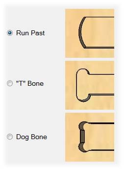
Dog bones / T bones
To understand why we need implement this type of fillets on interior corners, we should consider that a rounded mill bit will let a rounded corner and it can't make sharper corners that its own diameter. This can cause some problems when assembling the final pieces, especially if used on a precision joint like press fit. More info can be found on this useful page
T bone vs dog bone
 Illustation by Mozaik
You can use three filets to overcome this issue, the run past that creates an arc that can compensate the tool diameter, but it leaves a bigger impact. The T bone place the circles center on tangency from one of the lines, you can choose which one and use this to hide it. The dog bone is places in the middle so both lines will end up with a small feature.
The following video has a nice explanation about cnc fillets and how to draw them.
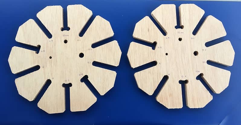
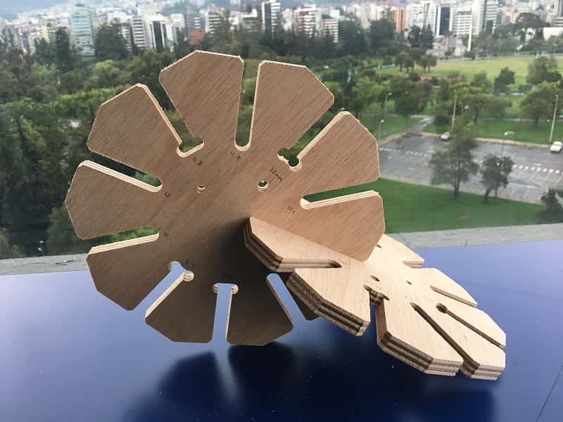
FITTING TEST
To make sure that we can fit the pieces perpedicular together, we needed to do a test with the material width
We downloaded the file from Dani's repository (Dani is a former student) and edit it for 12mm plywood.
You can find this file Here.
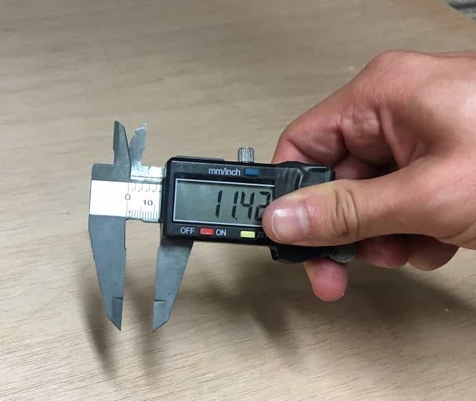
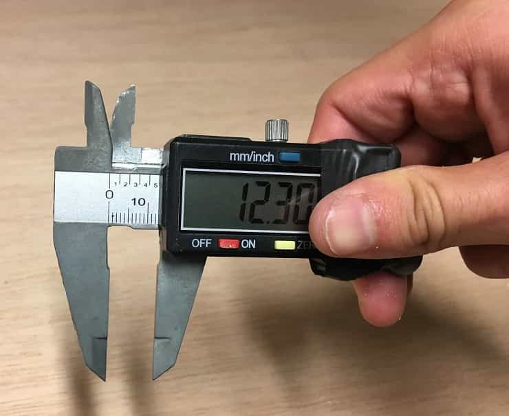
- Measure the material (12mm plywood, 1200 x 2400 mm)
- There is a slight difference between the thickness of the beginning and the thickness of the end of the board. This is a normal phenomenon, especially when working with living matter such as wood, which tends to contract and expand according to environmental conditions. This step is very important as it allows us to keep in mind considerations for the cutting parameters and also the design. Fortunately, the difference in measurements is not so great, which allowed me to work with an average to be sure of the cut.
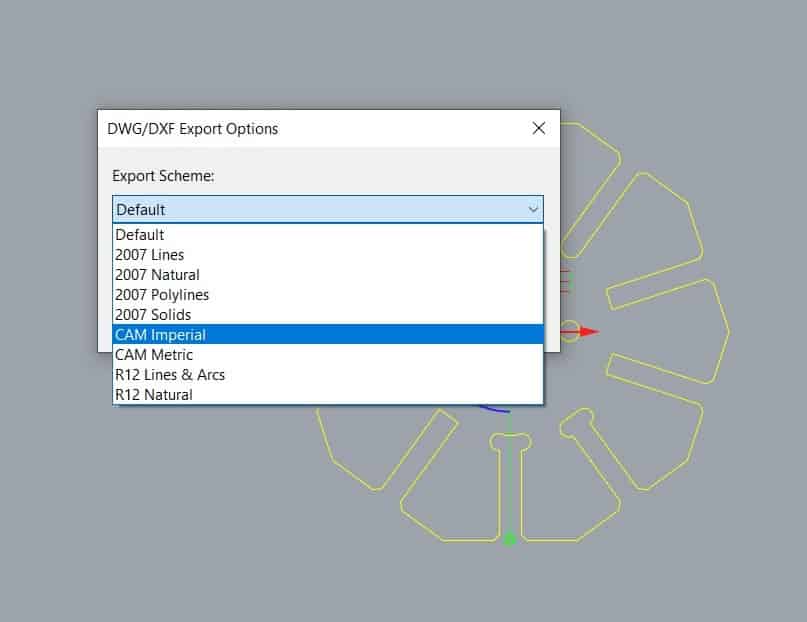
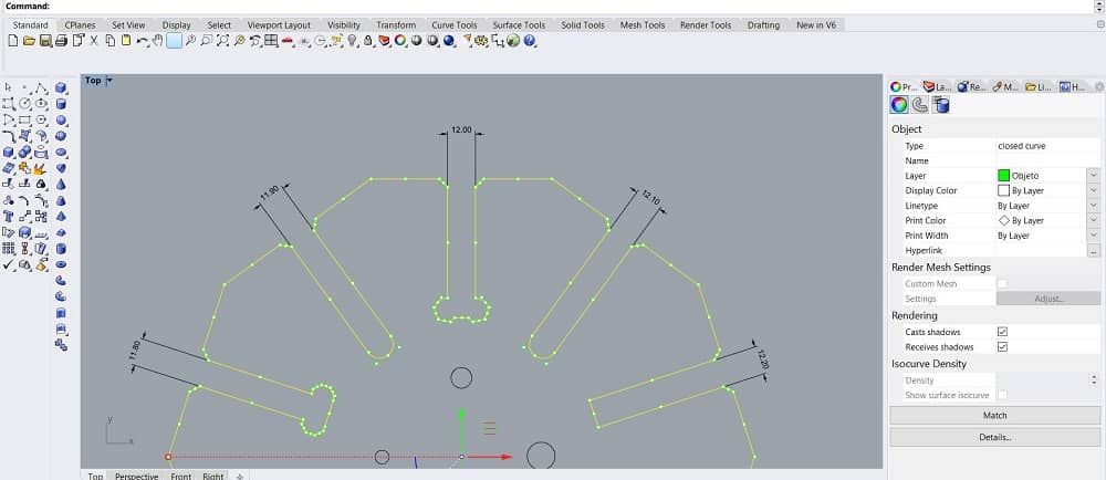
- Modify the file and adapt it to the new considerations. Scale it to fit the internal section to 12mm, and increase the separation by 0.1mm each to the right and -0.1mm to the left, as shown bellow:
- Select the pieces and export as .dwf and select CAM Imperial
ArtCAM WORKFLOW
Now that we know the material we have to set the file for cutting. In this case we used ArtCAM which is a CAM (Computer-aided manufacturing) software. Good for working in manufacturing, especially with wood engraving machines or similar.
- Open Art CAM and load the file. Vectors>Load
- Select .dxf file and open
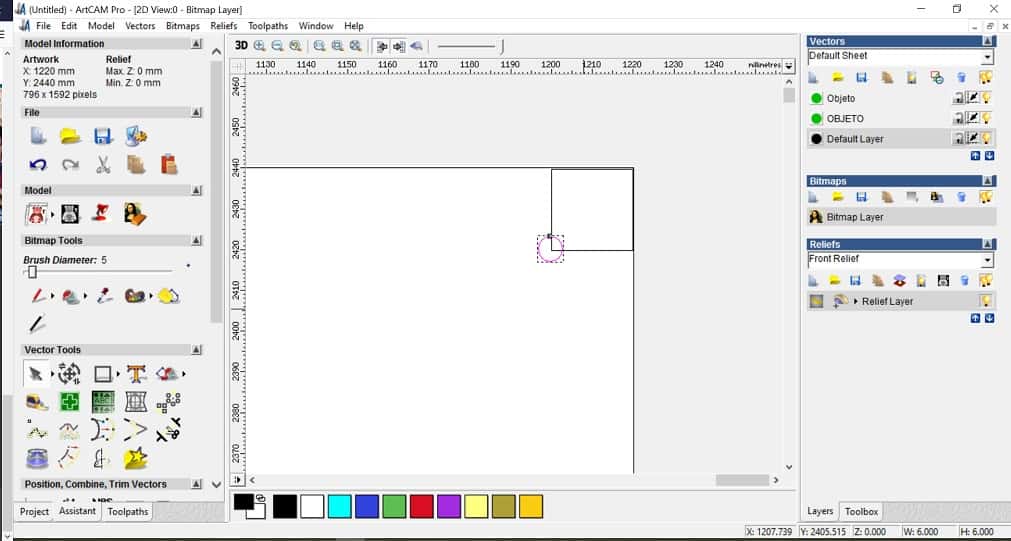
- Place the screws in the drawing. For this we drew a 20x20mm square and place it in the corners with a 4mm diameter circle that represents the screws.
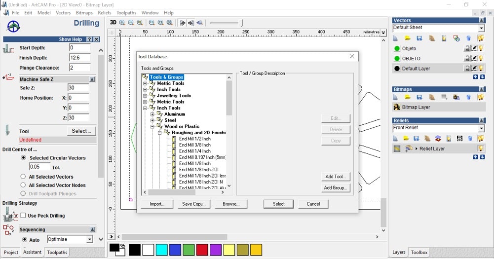
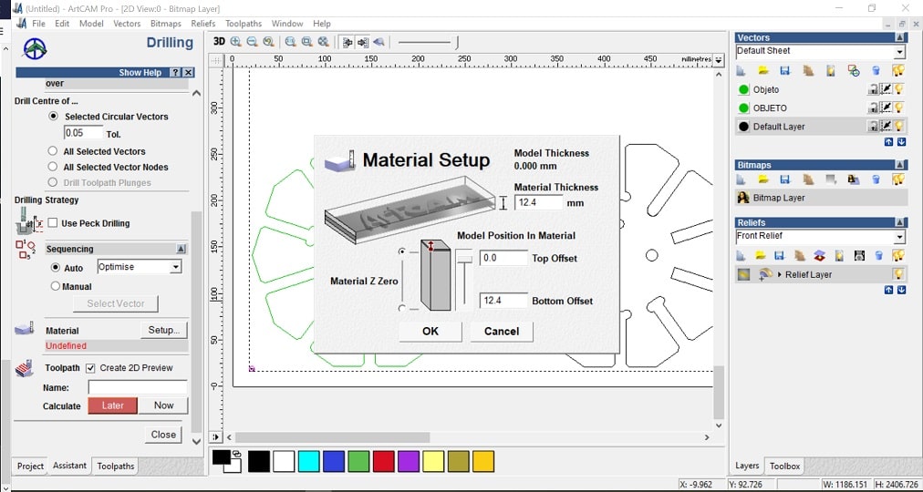
- Go to drilling options to set the parameters for the screws
- Start depth:0
- Finish depth:12.6 (because the material on it widthest part is 12.4, to be sure it cuts we increased it a bit.
- Machine safe z: 30 (this is where the end mill moves from one point to other without toching the material.
- Tool: select> routing and 2D finish> End mill 1/8 inch ZOI step over
- Material: setup> material thickness: 12.4mm > Model position in material: top offset: 0, bottom offset: 12.4mm. This depends on the material.
- Toolpath: name> now> write name
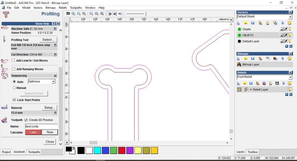
- Go to Profiling options to set everything for the pieces
- Prolifing tool: routing and 2D finish> End mill 1/8 inch ZOI step over
- Toolpath: name> now> write name
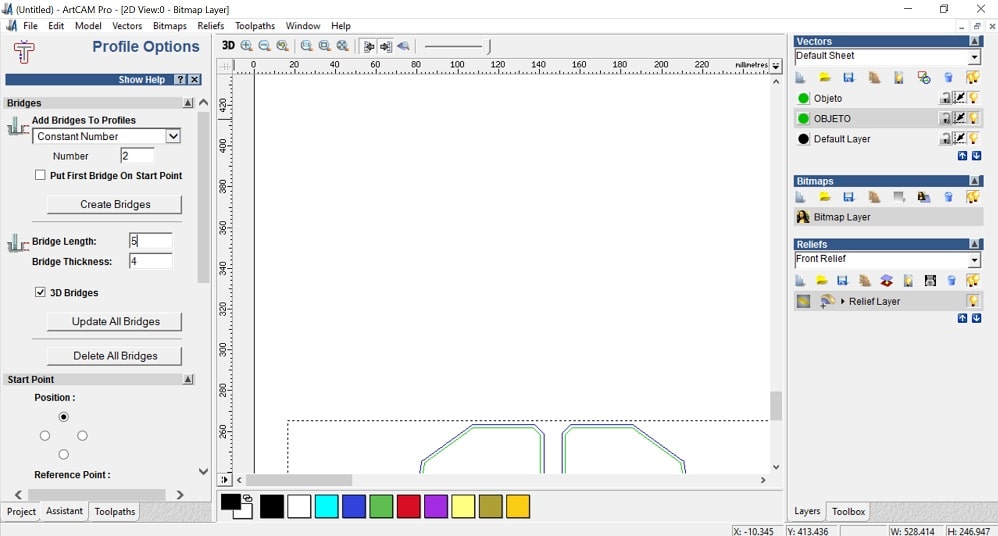
- Profile options: to locate bridges to hold the pieces while cutting
- Add bridges to profiles. Number: 2
- Bridge length: 5
- Bridge thickness: 2
- Double click on the model where you want to locate the bridges
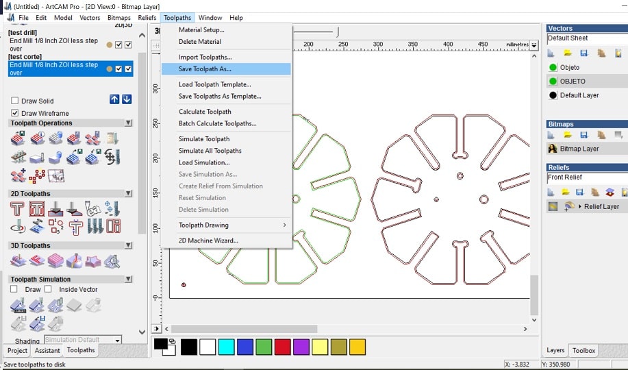
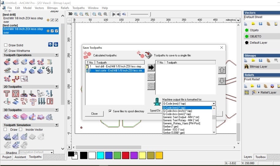
- Save the file: Toolpath> save toolpath as
- Select from the list on the left and push them to the right. Here you will find all the instructions you will send to the cnc machine.
FILES
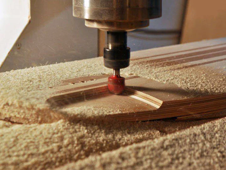
Fitting test.CNC WORKFLOW
With the .tap file ready we can prepare everything to cut
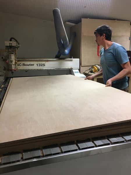
- Place the board on the cutting bed
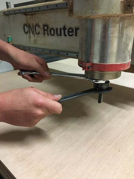
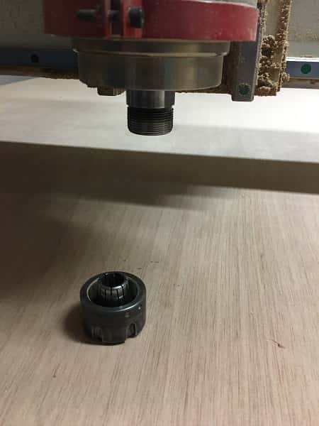
- Remove the nozzle to place the collet and the end mill we need for this work. In this case the 1/8". Make sure the collet and end mill are in the same units (mm o inches)
- Copy the file on a designated folder
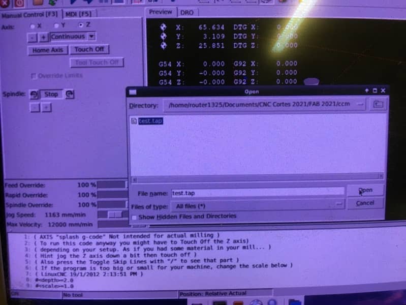
- Open the software
- Open the file for the drilling
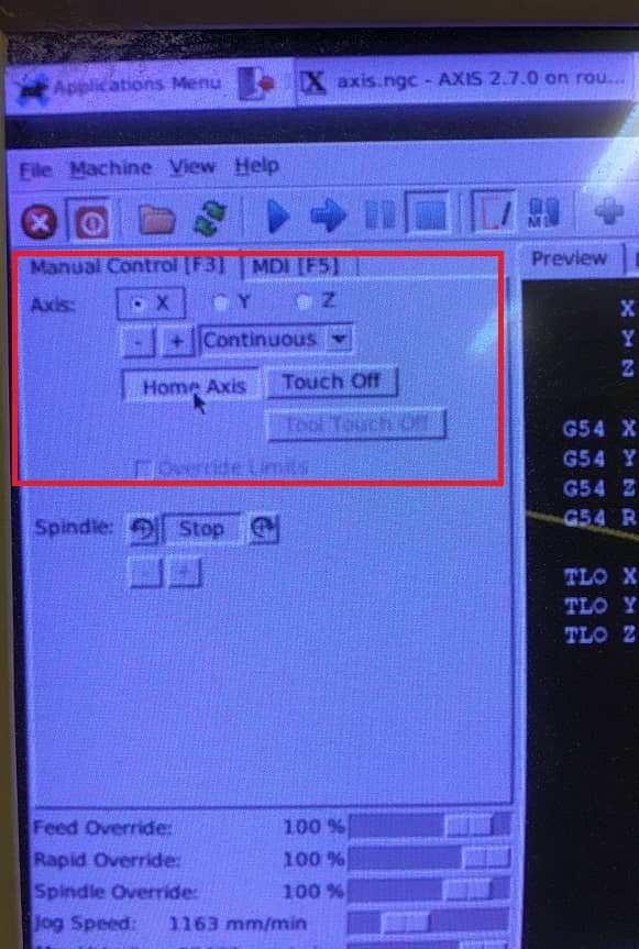
- Use the keyboard to set 0 for x, y and z
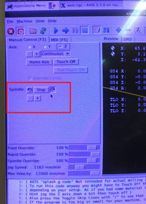
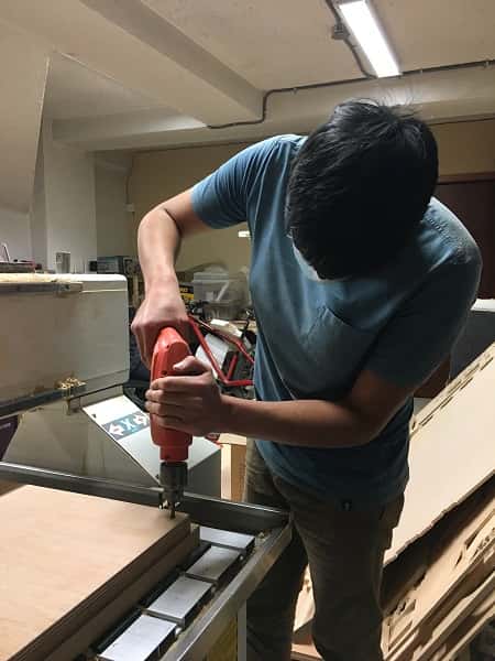
- Turnon the spindle
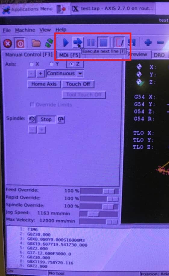
- To run the code step by step you can press "T" and to do it non stop press "S"
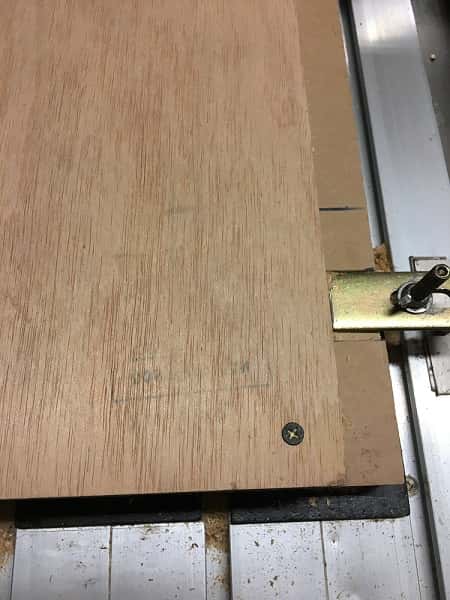
- Once the drilling holes are ready, put the screws to hold the material
- Keep the same configuration to cut

This is the final result
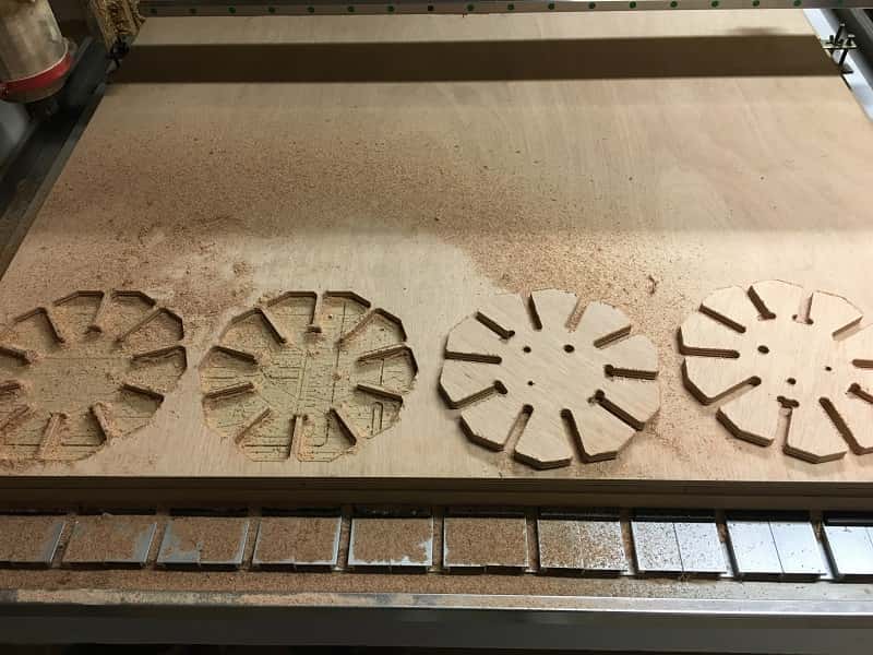
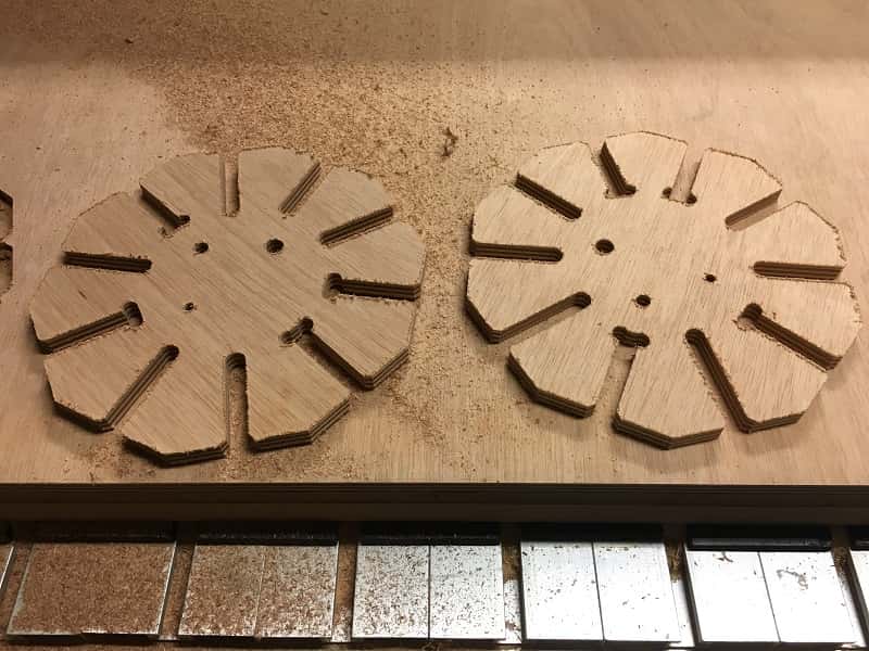
The size that fit the best is 12.2mm