Electronics Design

Jump to the hero shot!

Design a circuit board

When designing a circuit board is important to consider certain design rules. You first start by making a circuit schematic to do this is a good idea to have a diagram showing the board intended functions

Then you connect the different 'blocks' of the circuit to the MCU (if present), to finish your schematic. Then you have to create a board layout and wiring, planning where the traces go.

Using Eagle

I choose this program because it has a nice integration between the schematic and board workspaces, and this will help me as I'm not that familiar with electronics and probably I would have to change somethings on the fly and make several tries. Also, the integration with fusion 360 can be something nice to experiment with later.

After installing the program watch some tutorials on how to use the basics, like moving parts and right-clicking to rotate. The concept of layers and libraries. I download the Fab academy library for Eagle it can be found here. After some time figuring out how to import the library I succeeded.

Components of my circuit added to the eagle workspace

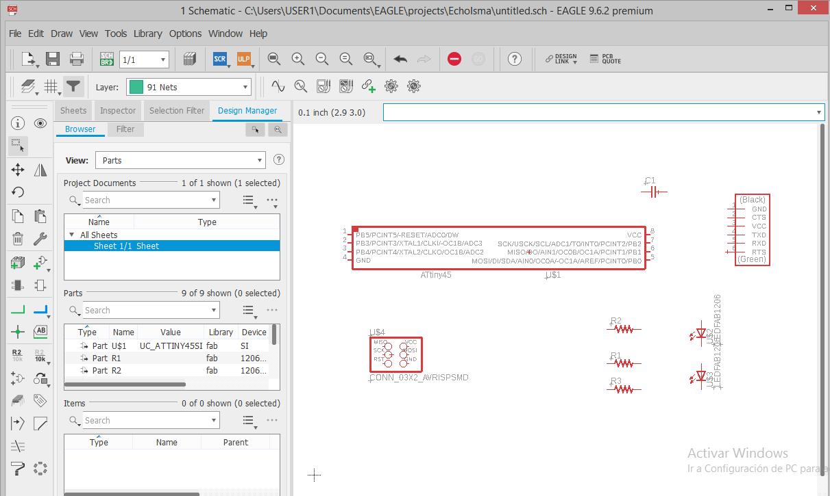
The next step was to insert all the components that I will need for my circuit, starting with the ATtiny45, in this step is crucial to choose the right parts and footprints

Complete circuit

Then I connected using the net tool and also the label tag tool, which can help you to give a name to some nets, and also if two names match they will be connected, which can simplify the diagram and make it cleaner. This was used to connect the ISP header to the ATtiny45.

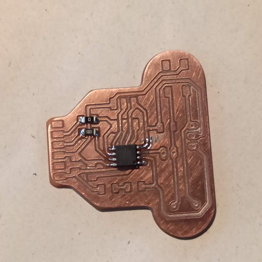
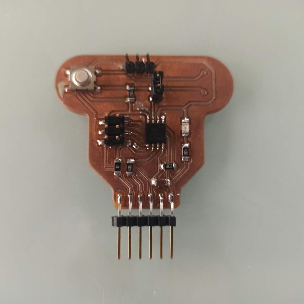
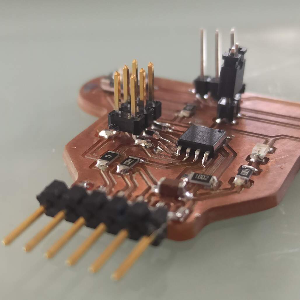
When the circuit schematic was complete I switched to the board workspace, while moving the components inside the board I realize that the LDR and the switch button can roughly reassemble eyes, so I decided to shape my board as a skull with the FTDI connector as teeth.

First idea of the positioning Final routes

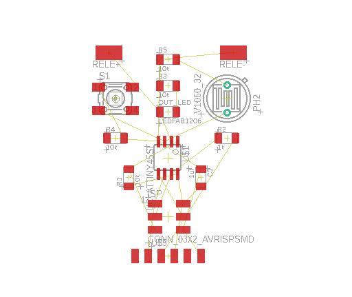
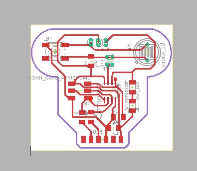
Wiring is something that takes me a while, is hard to start from nothing, so I imitate a bit the traces from the Neil echo board, adding traces and modifications to fit my needs.

I also have to include a 0K ohm resistor as a jumper to fit the VCC line underneath and use the switch button connected legs as a jumper.

Get the Eagle schematic file! Get the Eagle board file!
Eagle DRC were to find it

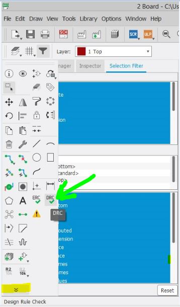
Also Eagle provide a tool called DRC (design rule check) that runs based on the setting and warns you about clearance and design issues that may affect the bard based on the manufacturing process used. At first I use only the default values. But then as I design more boards for other assignments this become a real useful tool.

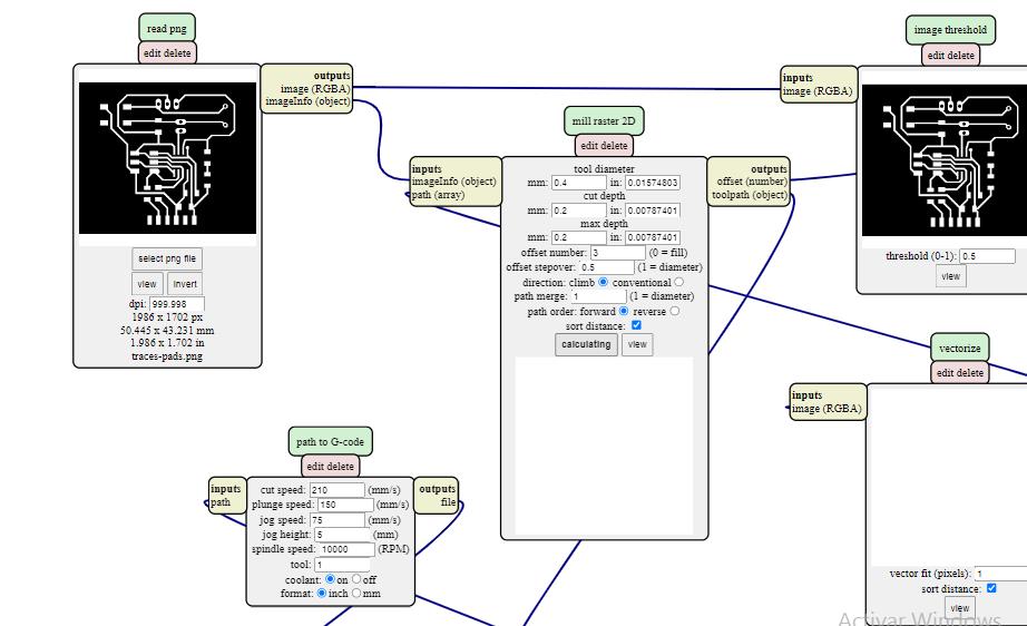
This is specially used to check clearance, based on the milling tool, I use 0.4mm to ensure that at least two tool pases to facilitate soldering and avoid sorts.

Eagle DRC were to find it Eagle DRC were to find it

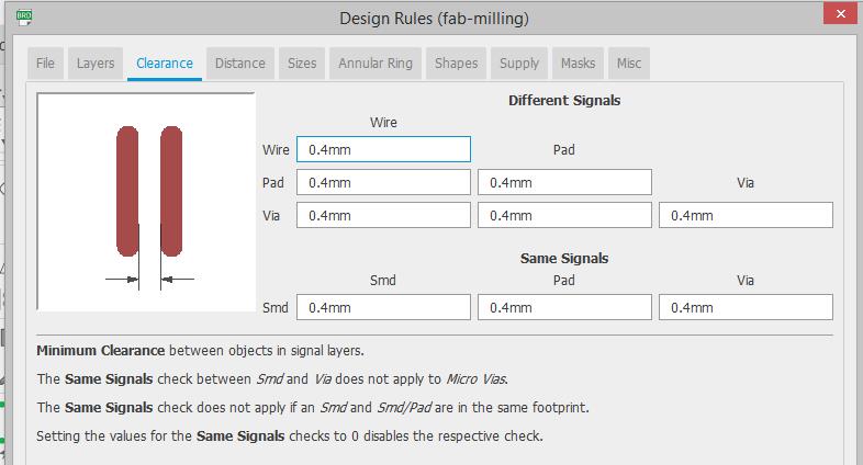
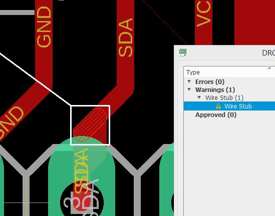
You can see the clearance settings used, and how it show a wire stub, to fix it I just delete some routes and re wire them.

Get the Eagle DRC config file!

Making the board

The idea is to repeat what we learned on the Electronic Production week, and then test that your design works. This is made on two steps milling and soldering, quickly explained below.

Milling the board

To generate the G-code I use the Mods png to mill program, I exported a png file of the traces from Eagle, making sure that the dpi was set to 500 or higher and the color scheme to monochrome.

Eagle export img Eagle export dpi detail

Here you can see were to export the current board as image, you can use the layer tab to only export that traces and then the outline. Make sure the dpi is grater than 500

Then I use Paint to remove some labels that were generated within the pads layer and save it as .png ready to use inside mods, note is important to click the invert button.

Once the G-code was generated and simulated, I passed it to the computer that controls the CNC machine, after loading the raw board, you should run the auto level program (it depends on the machine), and the mill the board, first the traces and then the outline.

Here you can see the board with just a few components

Here you can see the PCB milling machine making the traces, aside the board with just a few components on the lower right corner are the thinnest traces.

The resulting board was just ok, I think that something was wrong with the auto level and some of the traces were too thin, but luckily none was broken. So I decided to jump into soldering!

Soldering the board

Soldering the ATtiny testing the LED of echo board

Solder wasn't that hard, I have to make it at home, so I buy a new soldering iron, with a thin tip to solder SMD components. The only difficulty was with the trough hole components, as I didn't have a drill bit small enough. As the CNC just marked the places and made a small 0.2 mm hole, I use that to place the tips of the components and solder as SMD.

Testing the board

While soldiering I was double-checking the components and the continuity. The next step was to test programming the board. As it is a variant of the hello.ftdi.45 board by Neil I use the echo.c program gives as a example to test it. I also download the Makefile to have an easy way of programming and compile the c code.

I use my FabTinyISP created on the electronic production assignment to program this board via the ISP header. I use an Arduino as a serial bride (use tx and rx pins and hold the MCU on reset by grounding the reset pin) and the ArduinoIDE serial monitor. As shown below the board was recognized, programed and it makes an echo.

testing ISP connection make flash to program the echo board
echo output after successful programming

ATtiny45 echo hello-world mod by Isma

Finished Isma echo board top view testing the echo board Finished Isma echo board side view

Group Assignment

This week we have to see how an MCU was working on a board, we use an oscilloscope that was failing and was unable to measure at fast rates. So we make a blink Arduino circuit and measure the digital output going from 0v to 5v

See our group page!

Conclusions

This was a nice week because I managed to finish on time and even though the routing was really hard for me and it took me a good amount of hours to be satisfied with it. I'm glad that even though some traces were too thin the board works and nothing peel of or bridge while soldering.

I was very happy when my board works, also when I make a small program using the ArduinoIDE to test the push button. Is very exciting to make your own boards. I'm looking forward to seeing the possibilities of this in the future!

Have I?


Prev Next