CHECK LIST
Group assignment
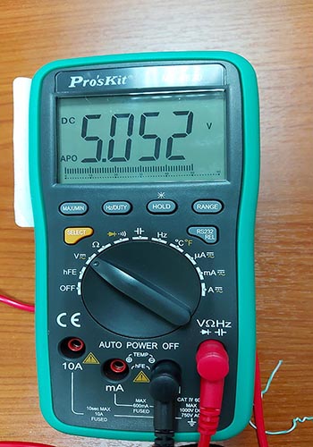
- Use the test equipment in your lab to observe the operation of a microcontroller circuit board (in minimum, check operating voltage on the board with multimeter or voltmeter and use oscilloscope to check noise of operating voltage and interpret a data signal)
OSCILLOSCOPE
Oscilloscopes (or scopes) display voltage signals as waveforms,
visual representations of the variation of voltage over time. The signals are plotted on
a graph, which shows how the signal changes. The vertical (Y) access represents the
voltage magnitude and the horizontal (X) axis represents time.
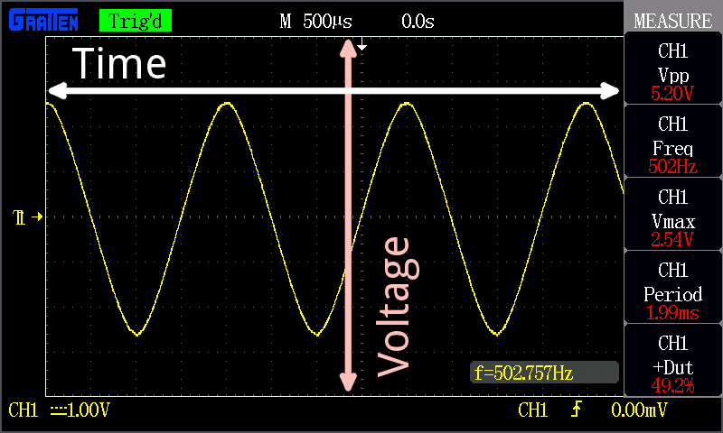
The graph on an oscilloscope can reveal important information:
- Voltage signal shape when operating as intended
- Current signal shape when using a current clamp suitable for using on an oscilloscope
- Signal anomalies
- Amplitude modulation of an oscillating signal and any variations in frequency
- Whether a signal includes noise and changes to the noise
First tests
This week we have to see how an MCU was working on a board, we use an oscilloscope that wasn't in its best state so it was unable to measure at fast rates. So we make a blink Arduino circuit and measure the digital output going from 0v to 5v
Our initial idea was to measure an analog input and compare with what the MCU was reading, also measure a PWM (pulse width modulation) signal to visually see how it made, but the sample rates needed to achieve that were way beyond the capability's of our oscilloscope
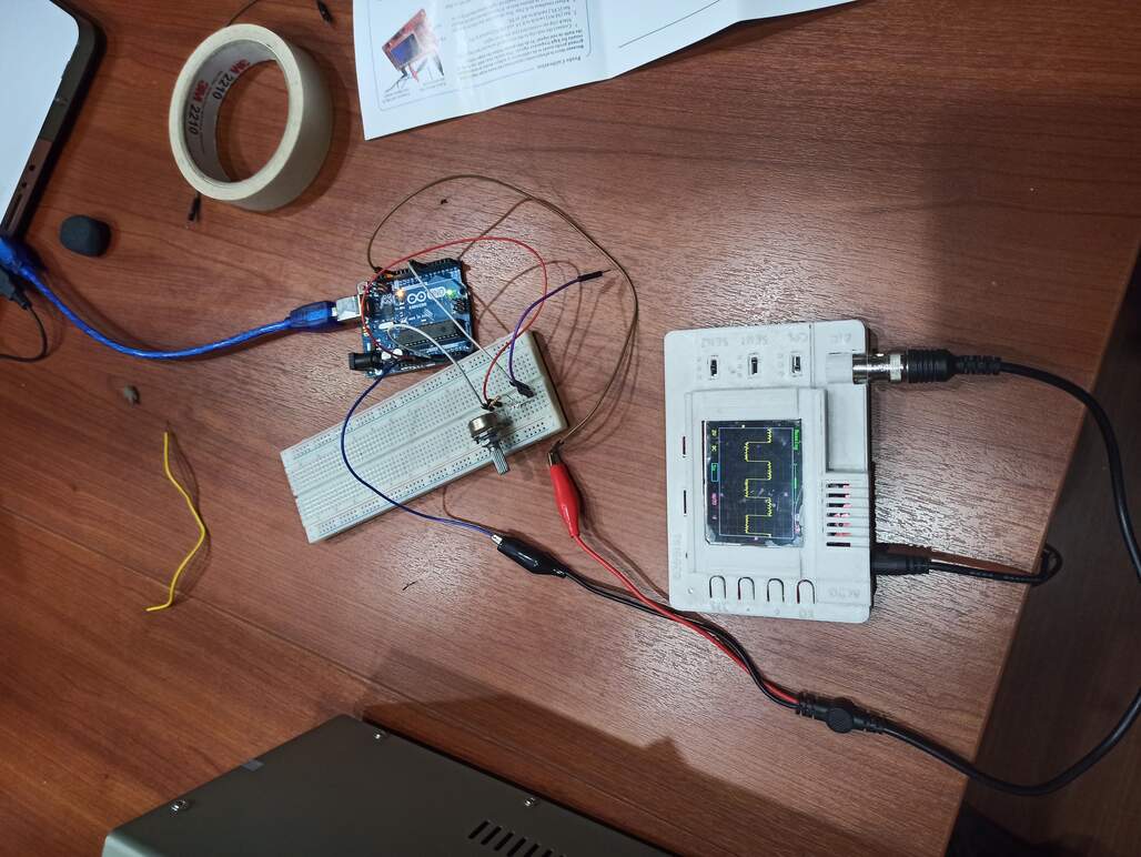
Our test set up
MULTIMETER
A multimeter or a multitester, also known as a VOM (volt-ohm-milliammeter), is an electronic measuring instrument that combines several measurement functions in one unit. A typical multimeter can measure voltage, current, and resistance. Analog multimeters use a microammeter with a moving pointer to display readings.
A multimeter is an electronics testing device that help us test multiple things including:
- Resistance
- Voltage
- And current. Using certain multimeter models, you can test to be sure that components such as diodes, capacitors, and transistors function properly.
- You can also troubleshoot your circuit to see where current is failing and pinpoint the problem spots
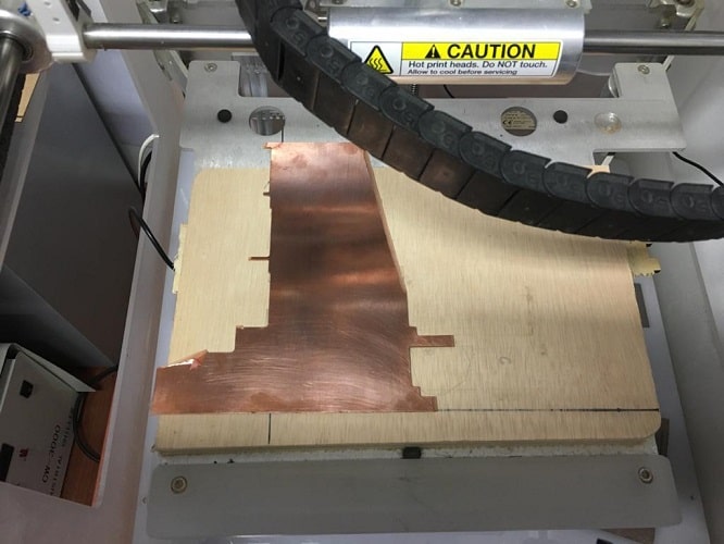
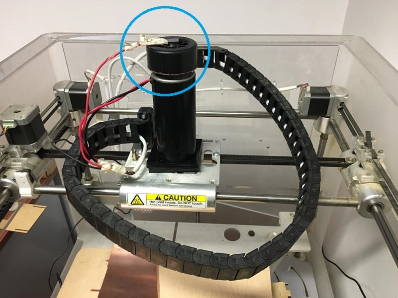
MILLING MACHINE
The machine used for this is one fabricated at the lab and hacked there.
WORKFLOW
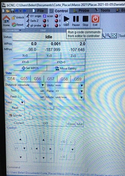
The software used for millin is bCNC.
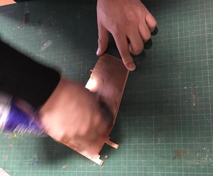
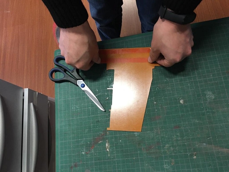
- Prepare the cooper plate with a metalic fiber
- Add doble faced tape and paste it on the milling wood board
- Make sure to paste the plate respecting the x and y axes marked on the milling board
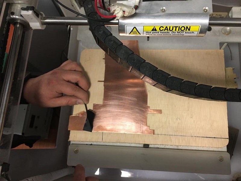
- Place the sensor on the copper plate and the magnet on top
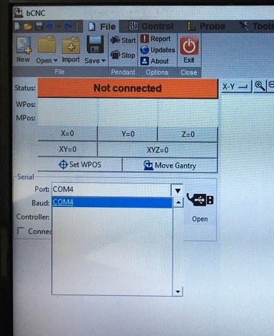
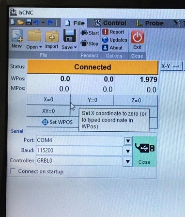
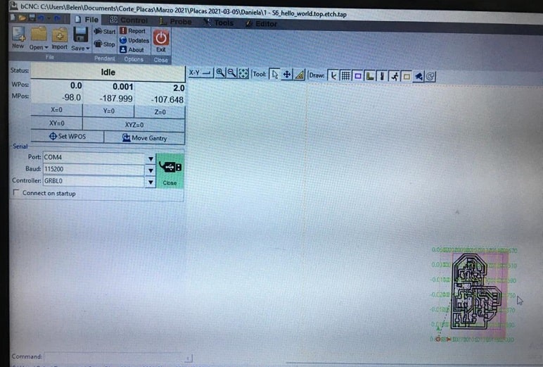
- File> serial> Band> COM4> Open
- Connect the machine to the computer usb
- Open file
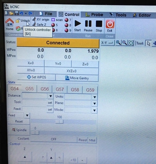
- CONTROL: unlock controler
- Set x, y and z axes on the milling machine using the arrows and when you are ready press x=0 y=0 z=0
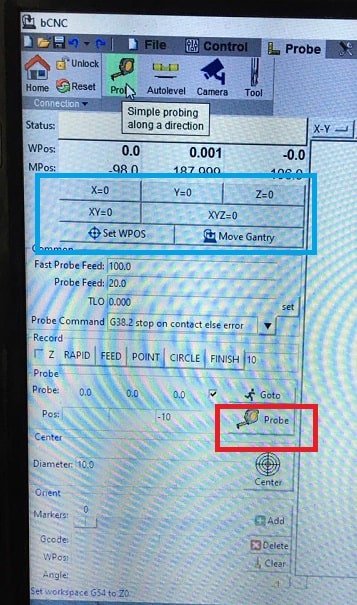
- PROBE
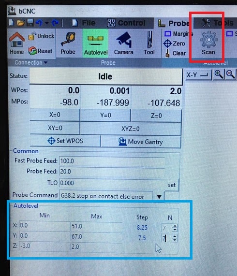
- AUTOLEVEL: you can copy the parameter on min and max from the gcode simulator
- Steps: 7 and 7 for this exercise. This means there will be 49points (7x) where the end mill makes contact.
- Scan and after a couple of minutes when the scan is done, press probe
- File: save the .probe
- Press zero to set the origin
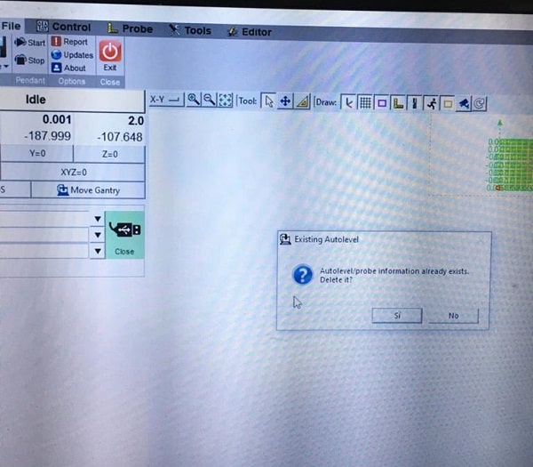
- Load .probe file and traces file
- A mesage about an existing .probe file will come out: replace it!
- Disconect the magnet on top
- Turn on the spinner
- CONTROL: start
- For the border: load file
- Press start. In case you need to stop you can press pause or stop in the control pannel