Designing the board and 'screen'
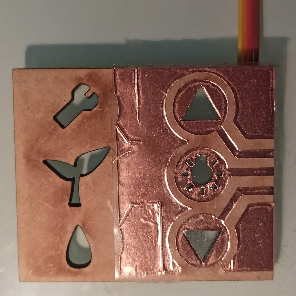
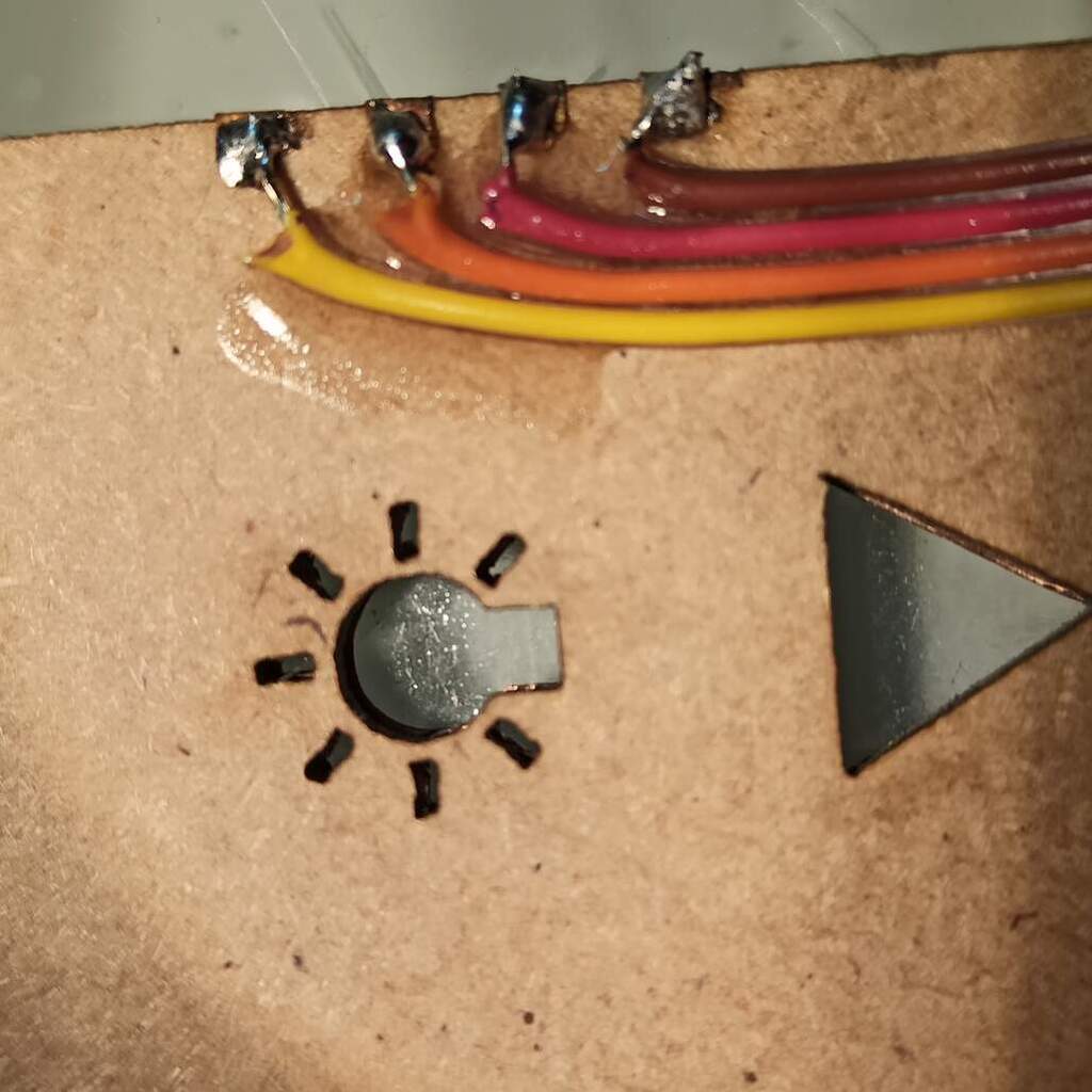
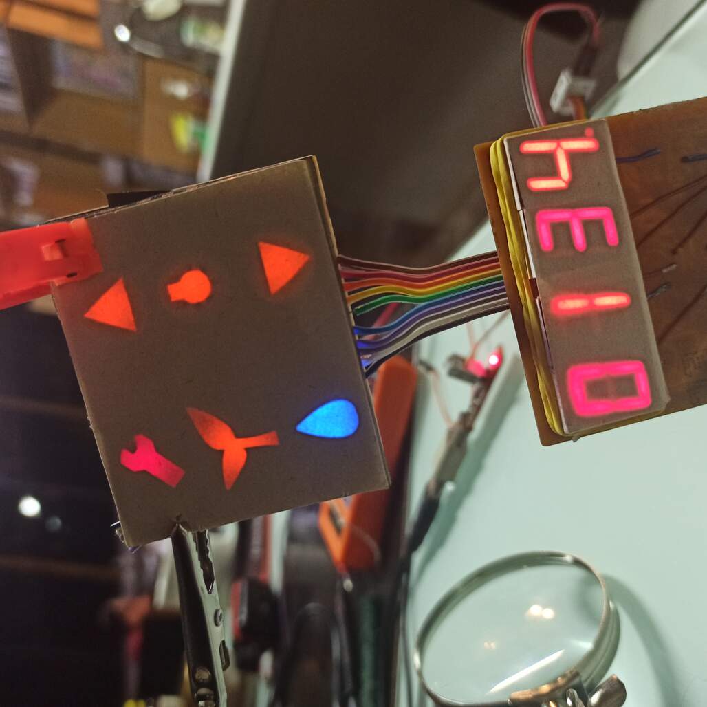
I decided to use this assignment to create a 'screen' or user interface that will be used on my final project, the idea is that some back lighted icons an 7 segments display, hidden behind a this veneer wood, will give the user feedback about the state of the machine and some basic configuration.
When I was planning how to make this board, I found that all the 'small' (ATtiny family) microcontrollers that I may use for the display were out of stock on the lab, Roberto my instructor suggested the ATmega328p. I then design a board that will, hopefully, the main board of my final project. It will drive the 'display' and also the water pump and the LED strip. and be capable of interfacing with some external sensors.
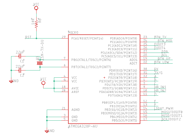
Main schematic of the board, how the ATmega328p is connected to other modules.
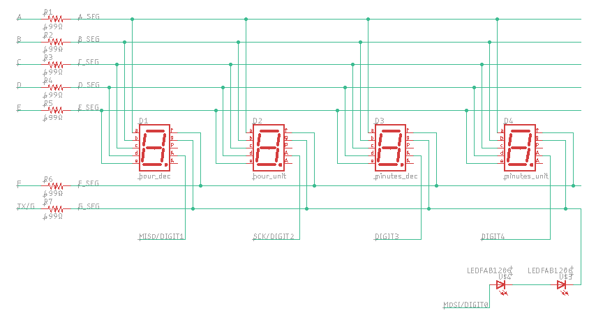
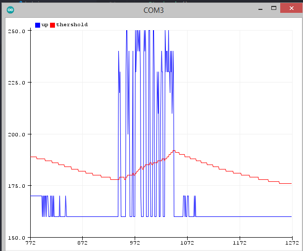
Module of the icons and touch sensors
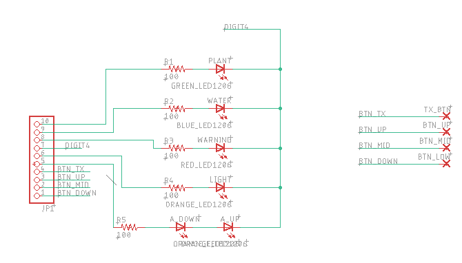
Module of the icons and touch sensors, counted as a 5th digit for multiplexing.
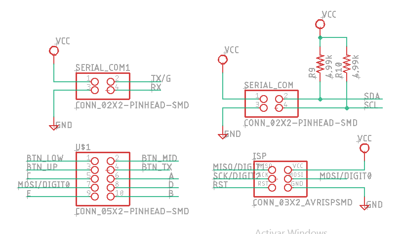
Module that manages serial communication, note there is an error here, see the update
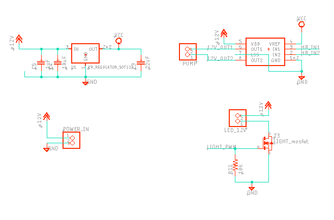
Modules that manage the H bride and mosfet.
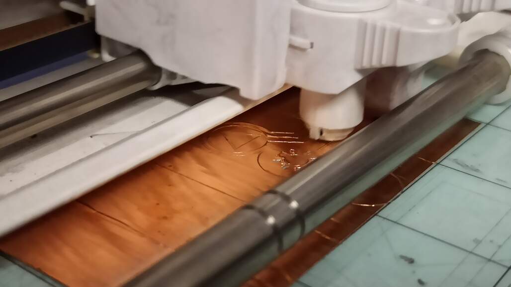
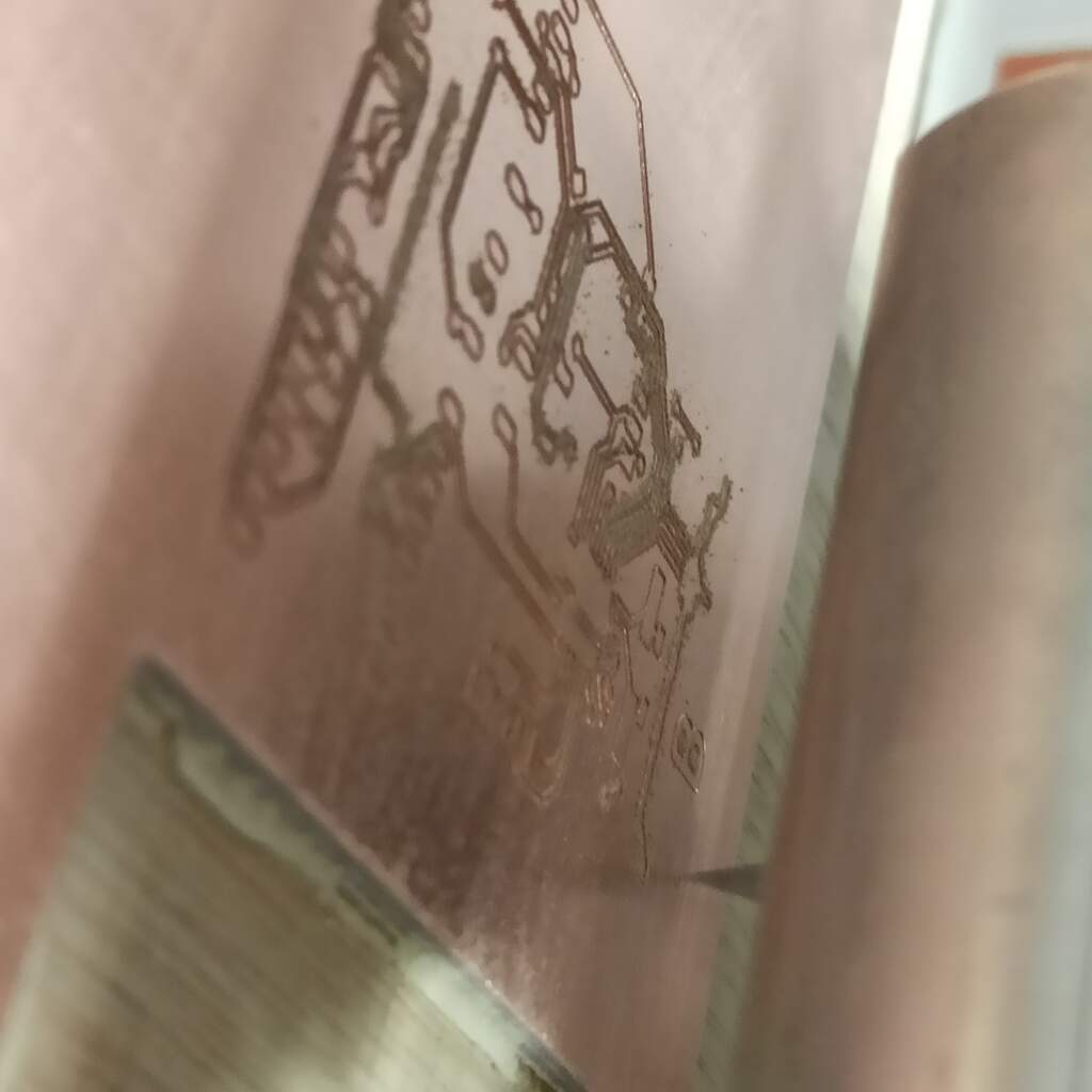
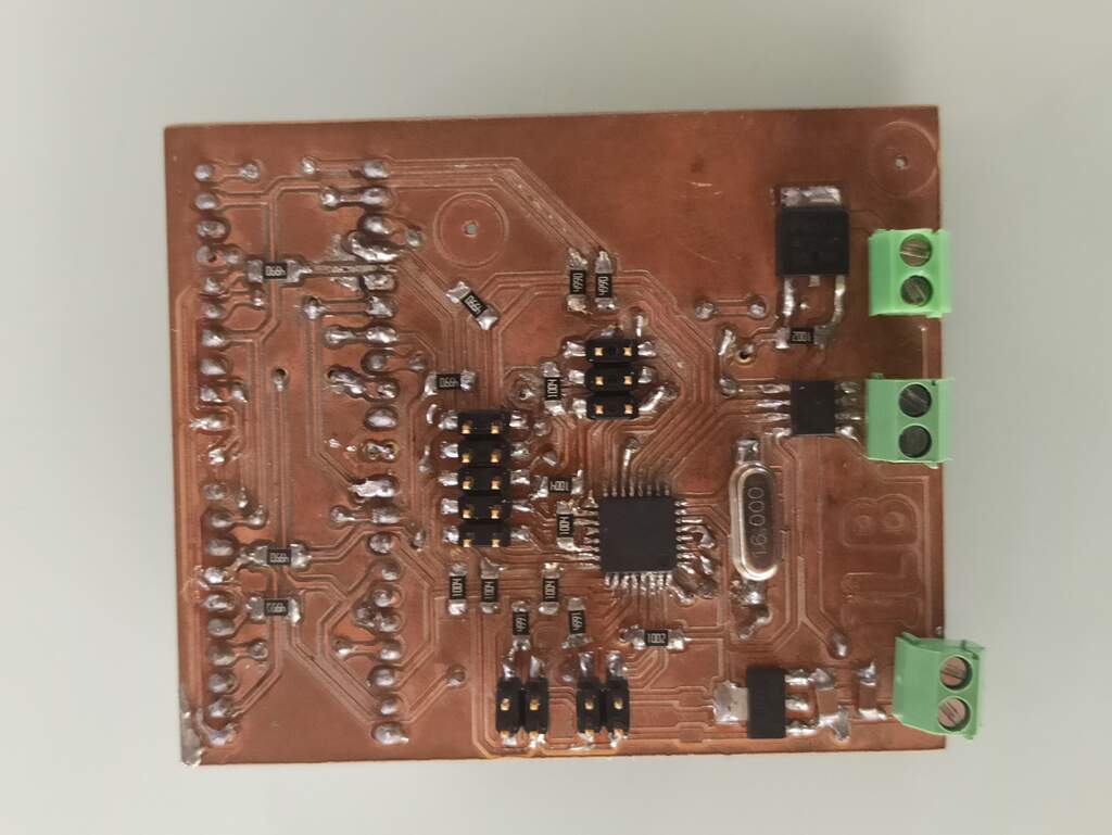
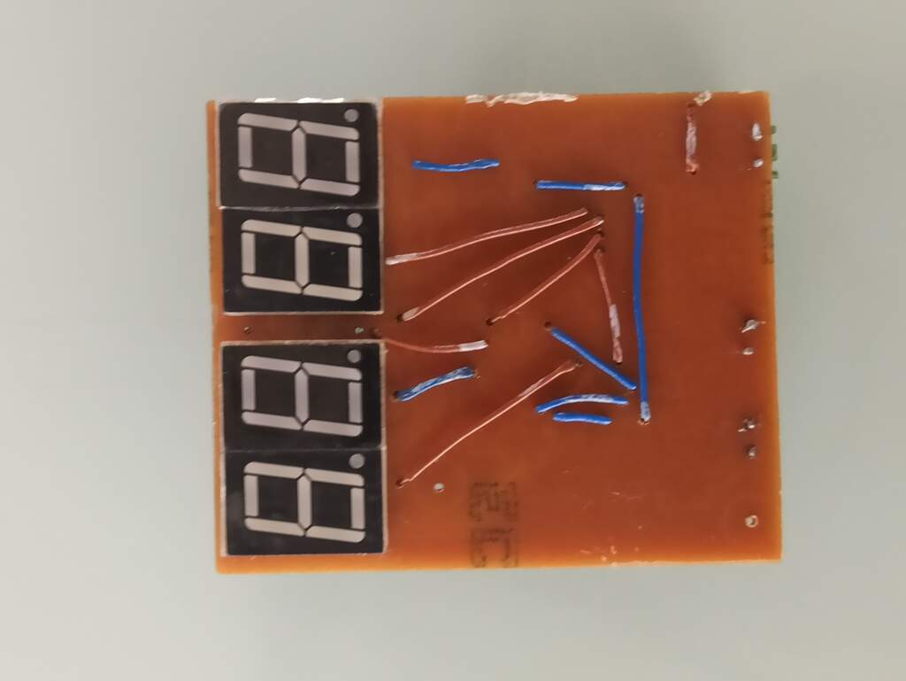
Boards created from the schematic
I created two boards that will be connected by a ribbone cable, as one needed to be placed vertical and the other is located on top of the project.
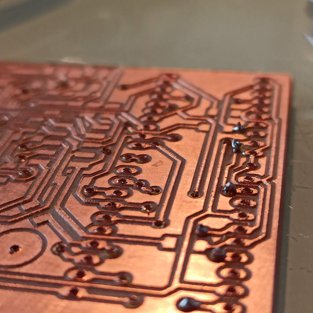
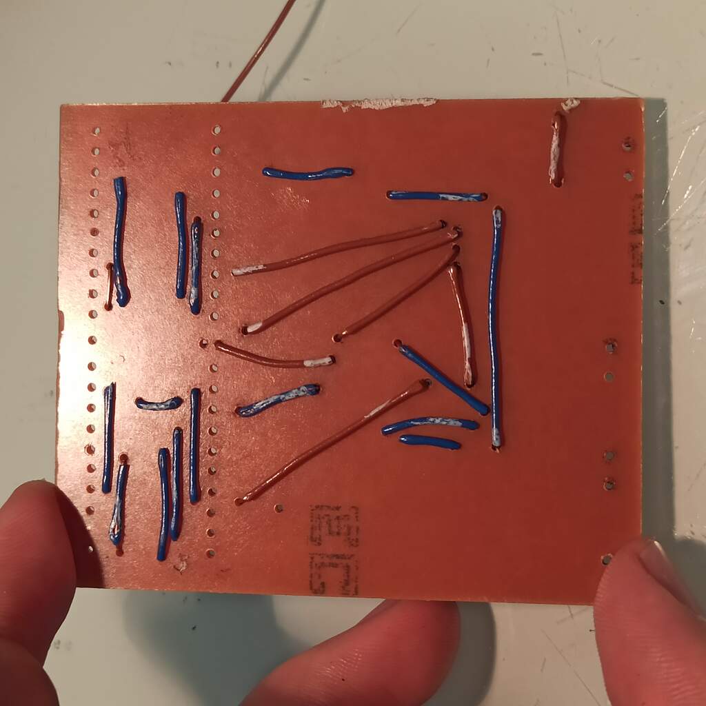
The routing of the main board was a bit difficult and I also put the 7 segments display on the back side of th board so it will fit the position on the final project assembly. I also have to use some jumper wires that are represented as straight traces on the bottom layer.
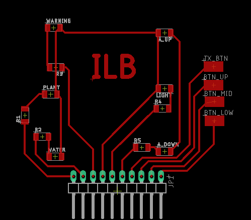
User interface board, contains the led icons and the touch sensors.
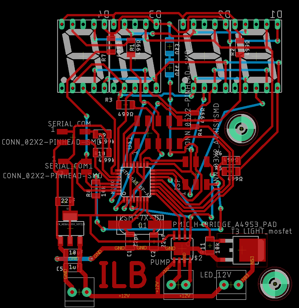
Main board, contains 7 segment, serial, power, and power outputs modules. Note is now updated below
Update!
The previous schematic and board were missing 1MΩ resistors for the touch sensors, I have fabricated a new one, that features those changes, the design files are now updated.
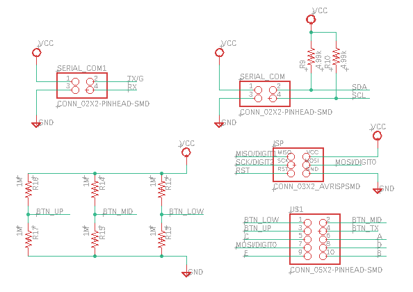
Updated schematic it now contains 1MΩ resistors for the Rx pin of each button
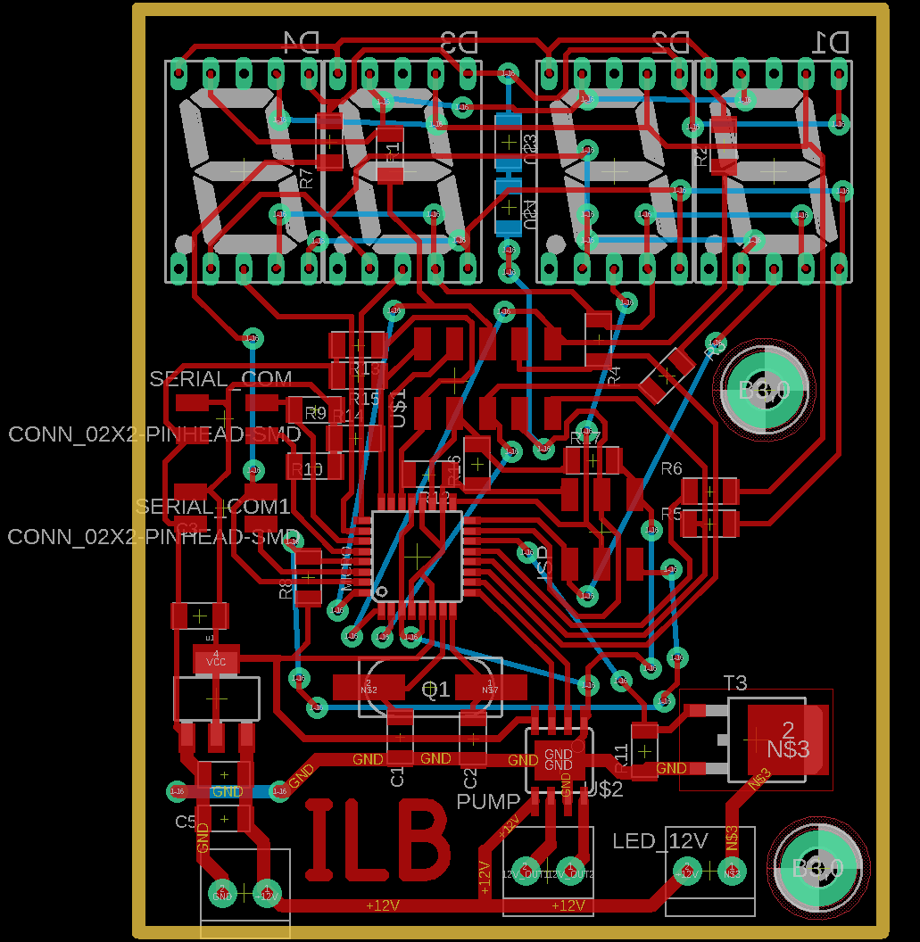
Updated board design, note it now contains 1MΩ resistors and is routed different
Design files updated
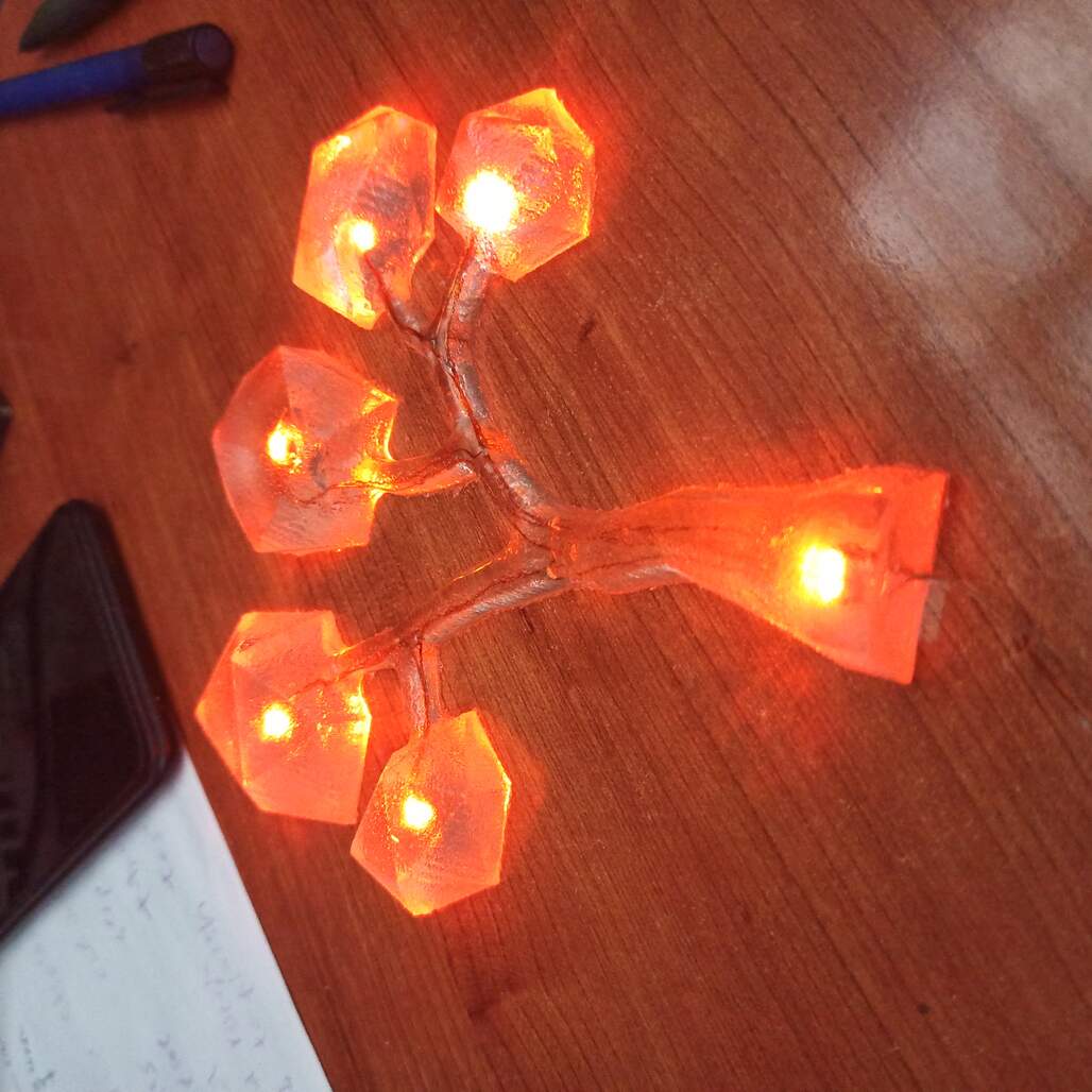
CharlieTree, designing a board for charlieplexing
I embedded some LED's on the tree I design for the molding and casting week, they were connected on a 6 led 3 wire charlieplexed matrix, the idea is to have a night lamp that will animate the brightness of each led and then turn off, it should be powered by batteries and have a lower power consumption so it will last long without needing a change.
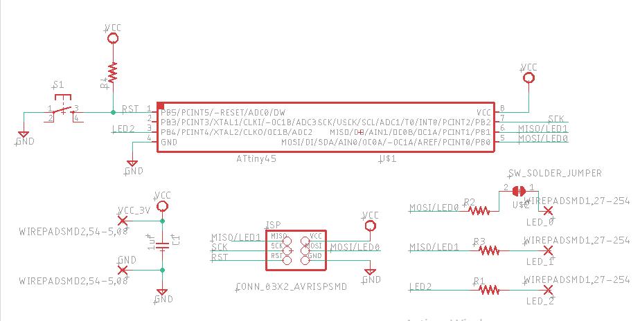
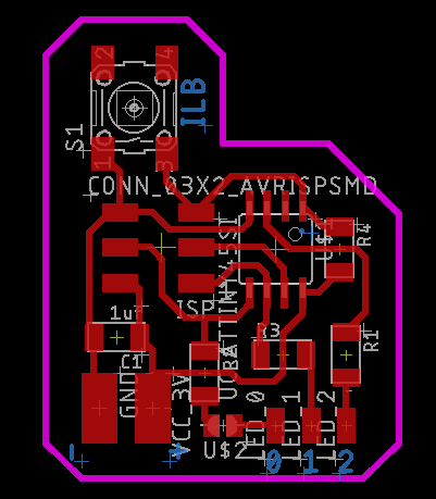
Simple board and schematic, it includes a push button as wake up button and animation configuration, also wire pads for the 3 LED lines and battery cables.
Get the .sch file! Get the .brd file! See how it was programmed!