Programming
 I intended to use I2C, to program the peripheral I follow this tutorial, as the original program to measure light (you can see how it was coded here) use on that board was write using arduino. Following this tutorial wasn't that easy, because on the git repo the master branch isn't working, you have to download the rollback branch.
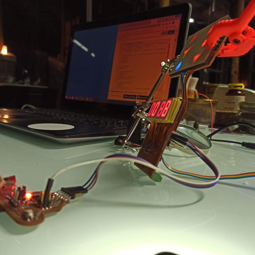
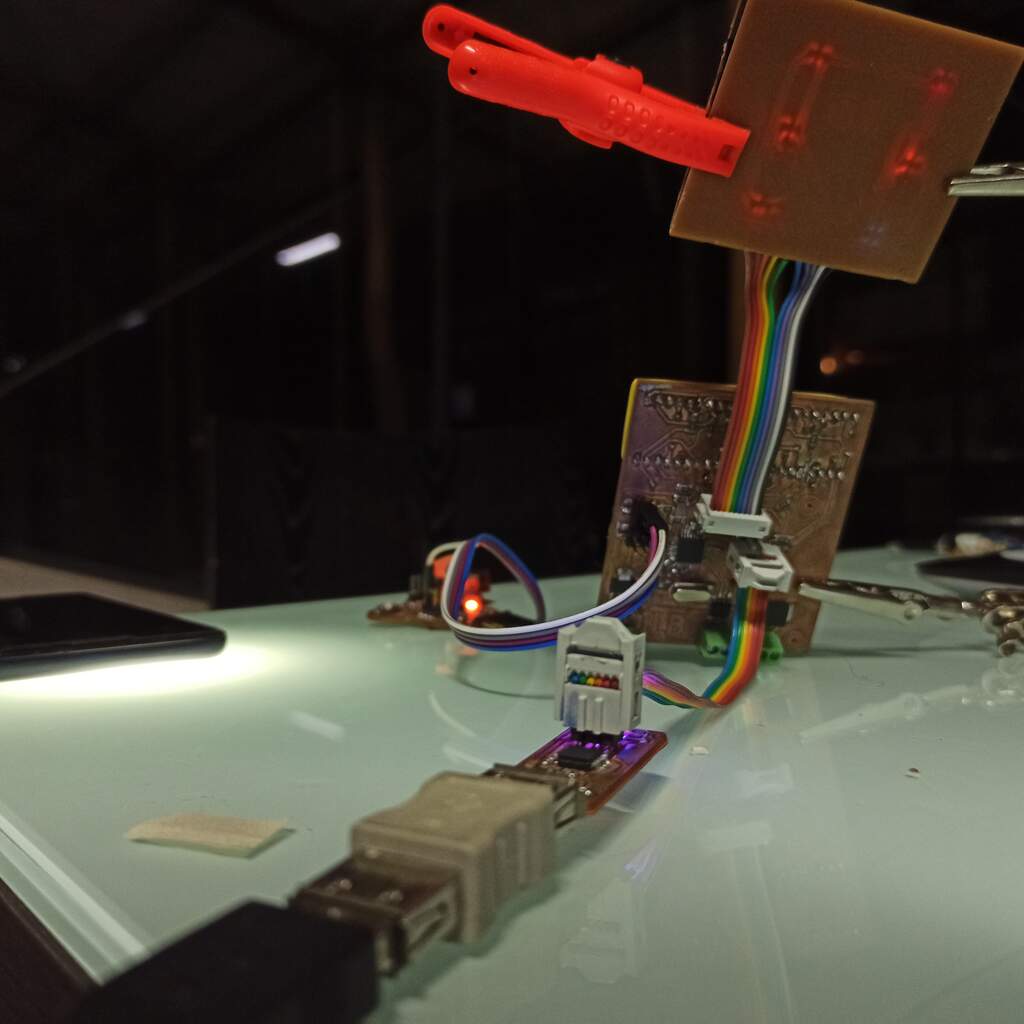
To troubleshoot I use an Arduino Uno as master to communicate with my peripheral board, test the addresses and the value sended using the serial port.
The TinyWireS library has a begin() function were you define the peripheral address, and then you can hook custom functions too manage the onReceive and onRequest from the controller. I only use the onRequest function to send 1 byte back.
void requestEvent(){
  int test = 26;
  TinyWireS.send(test);
}
When that was working I split the 16bit value from the measurement on to lowByte and highByte and sent those via I2C bus. On the master I request two bytes and reassemble the 16bit number.
//Peripheral
  void requestEvent(){
    TinyWireS.send(lowByte(ilum));
    TinyWireS.send(highByte(ilum));
  }
//controller (test code for Arduino UNO)
  void loop() {
    int bytesRecived = Wire.requestFrom(4,2); // 4 is the hard coded address
    Serial.print(bytesRecived); // used to debug
    Serial.print(" ");
    while(Wire.available()){
      byte low = Wire.read();
      byte high = Wire.read();
      int lightValue = low | (high<<8);
      Serial.println(lightValue); // used to debug
    }
    delay(500);
  }
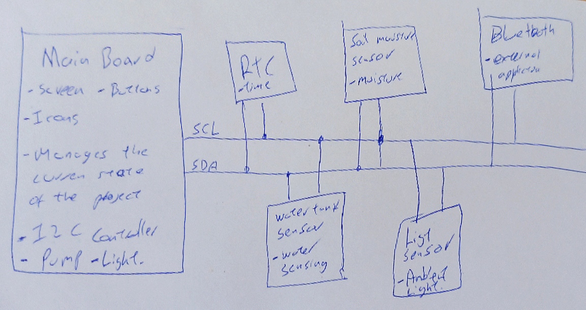
Coding my main board as controller
On the Output devices week I program the board to multiplex and sense the touch input, all of this was written in C/C++ using direct port manipulation that allow me to have more speed to multiplex.
The I read the ATmega328p datasheet and I found that make the protocol via direct port manipulation will require a lot of work. I decided to browse for a library that may reduce the work needed. I couldn't find any that I manage to compile my code with. So I decided to use the Arduino core and use the Wire.h library. I use PlatformIO and place my C code there to use the multiplexed display.
Both boards were programmed using the FabTinyISP and ths SPI protocol.
I the use almost the same code used on the Arduino Uno, and display the 16 bit value on the 4 digit display.
void DisplayInt(int value){
  if(value>9999) return;
  uint8_t buffer[4] = {10,10,10,10};
  for (uint8_t i = 0; i < 4; i++)
  {
    buffer[i] = value%10;
    value = value /10;
  }
  //Set the display digits
  displayDigits[1] = buffer[3];
  displayDigits[2] = buffer[2];
  displayDigits[3] = buffer[1];
  displayDigits[4] = buffer[0];
}