Input Devices

Jump to the hero-shot!

The idea

As this week assignment was about developing sensors I was motivated to experiment with capacitive sensors and test if I could use them on my final project. The idea is to make a board that will integrate different 'techniques' of capacitive sensing to test the possible applications and uses.

Step response and capacitive sensors

The idea behind the step response sensors is that the microcontroller sends a 'step' and you measure the response of the connected input device. You usually attach a simple circuit that allows you to measure a change on capacitance or resistance.

I found this useful video that explains how capacitive sensors work


Group Assignment

On this assignment we probe and compare serial and digital signals from sensors.

See our page!
Comparison between analog and digital signals


Fabrication

Main board

I use Eagle to make the schematic and board layout of this test circuit. It is based around the ATtiny44, that has a Analog to Digital Converter (ADC), that can be used with a internal multiplexer to 8 pins.

This board will try to use a square signal and a set of capacitors, two step and load sensor, two transmit and receive step sensor. As outputs it will integrate a TX pin to interface with a serial device, a LED and maybe an output for a relay.

Schematic of the step sensor board Board step sensor layout

Then I use a CNC machine to mill the board, and then stuffed it with the electronic components.

Finished board

Sensors

I also experimented with the shape and size of the sensors, for that I used the Copper Foil Tape included on the inventory.

I only take the row tape to experiment with it at home, because my lab access this week was limited due to mobility restrictions by the pandemic. But luckily I have a thermal laminator, that I use to laminate the sensors and provide a structural an isolation layer to the sense probe.

First I sketch the sensors shapes and dimension, then I use a pencil to draw on the back of the adessive copper tape, and cut it using a pair of scissors.

Board step sensor layout Board step sensor layout

Then I paste the copper tape on the laminate sheet, and make some holes with a hot tip were I intend to solder the wire. After that I laminate the sheet and cut the sensors. Maybe for future iterations I will use the vinyl cutter machine to have cleaner cuts and more accurate dimensions, as well as a smaller size especially on the touch sensors.

Schematic of the step sensor board Schematic of the step sensor board Schematic of the step sensor board

After cutting and soldering some wires I also use hot glue to isolate the solder pints and make the sensor water tight to use it with moisture and water without any problem.

Capacitive soil moisture sensor

Soil moisture sensor

Capacitive water level sensor

Water level sensors

Capacitive touch sensor

Touch sensors

Picture of all the sensors fabricated

All sensors

Programming

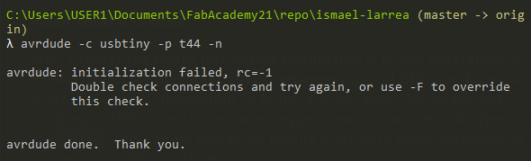
After some troubleshooting (you can see the details here), I manage to establish a connection between the FabTinyISP and the ATtiny44 in order to program it. I use PlatformIO and the VScode IDE to develop the code.

The first thing was to install the SendOnlySoftwareSerial library, that allows you to only use 1 pin to send data and only implements send functions.

Then I create a sketch that test the serial communication and it didn't work, the PlatformIO pinot some how is different and it uses the alternative pinout detail on the next image.

ATtiny44 pinout

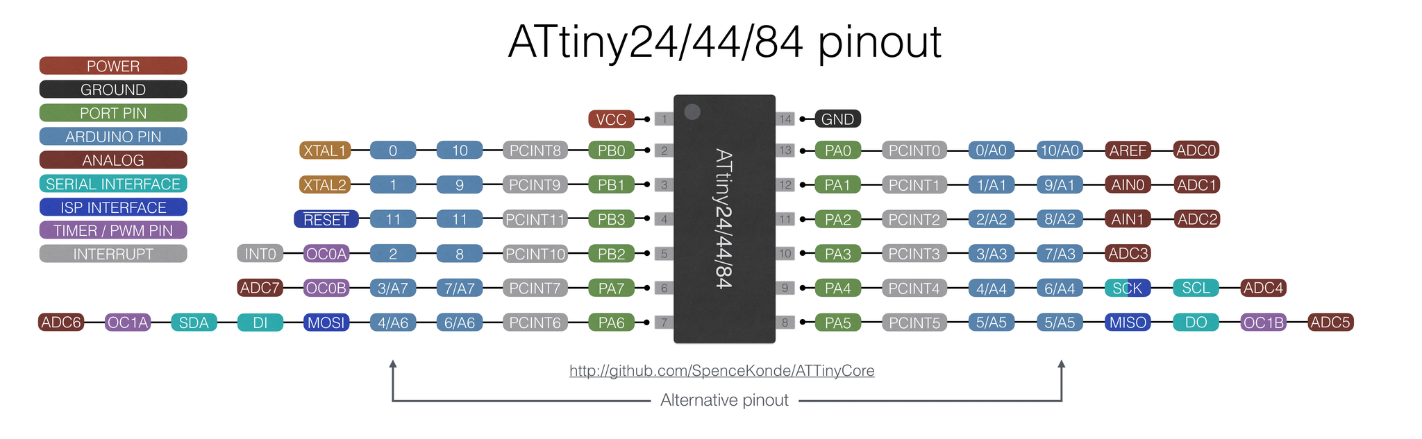
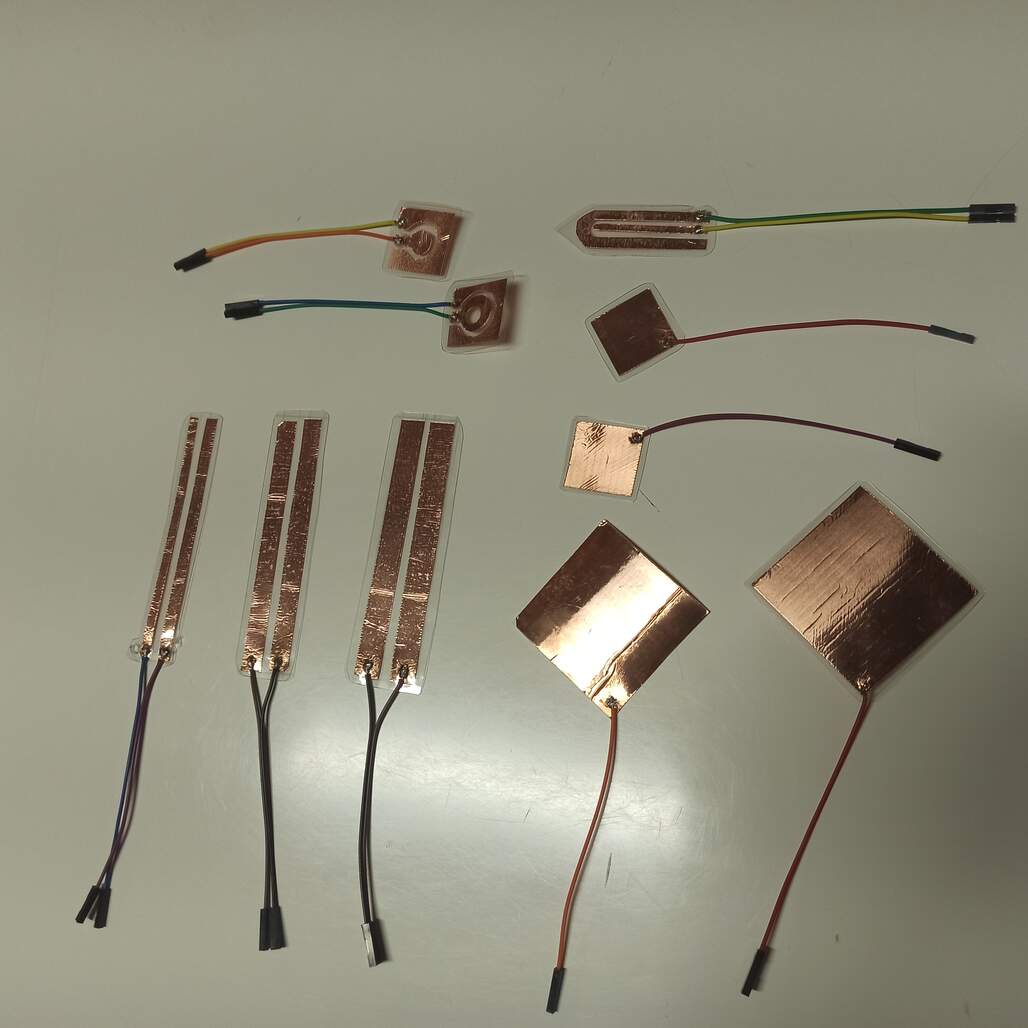
Using this pinout I was able to get the serial communication working and start with the sensor interfacing. The load sensor work just a bit when trying with the AnalogRead() function, but then I use direct port manipulation to the step and also to control the ACD. But the output value was noisier and difficult to use as a reliable input, by analyzing Neil's .c and .py code I found that a 'filter' implemented on the python code, maybe implementing that on the microcontroller will 'clear' the signal, but I decided to test the other sensing methods.

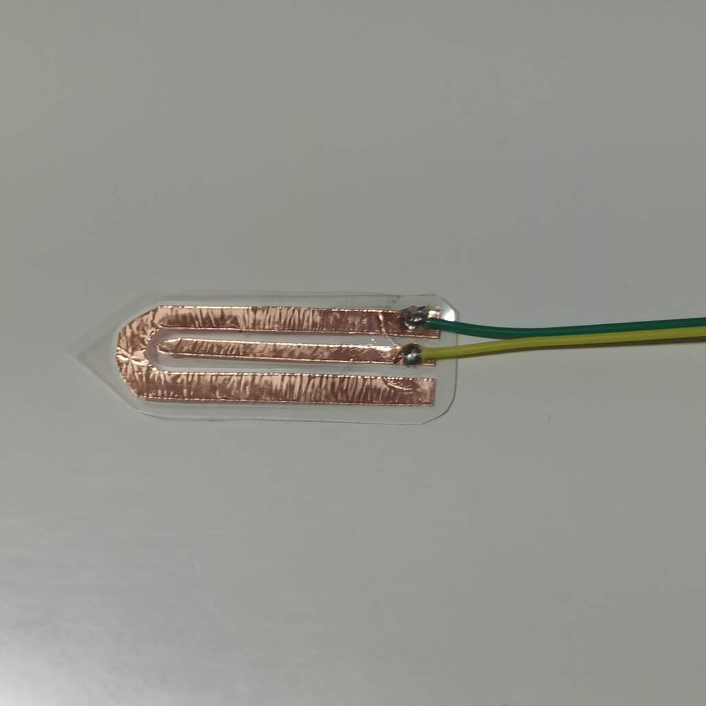
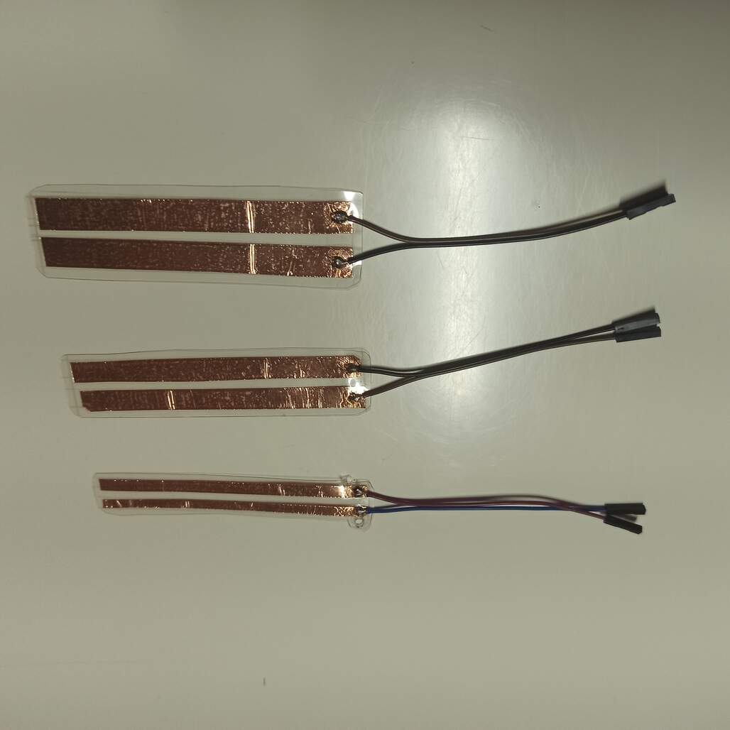
The transmit-receive method work a lot easier, using Neil's code as reference I was able to get a stable and clean reading, by connecting my own touch sensor I get a good reading on touch, this can also be used to measure water level but I didn't test it out yet.

Comparison between load sensing and transmit-receive sensing

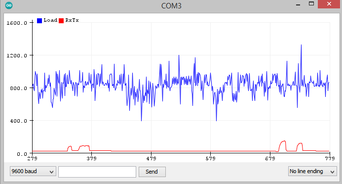
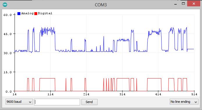
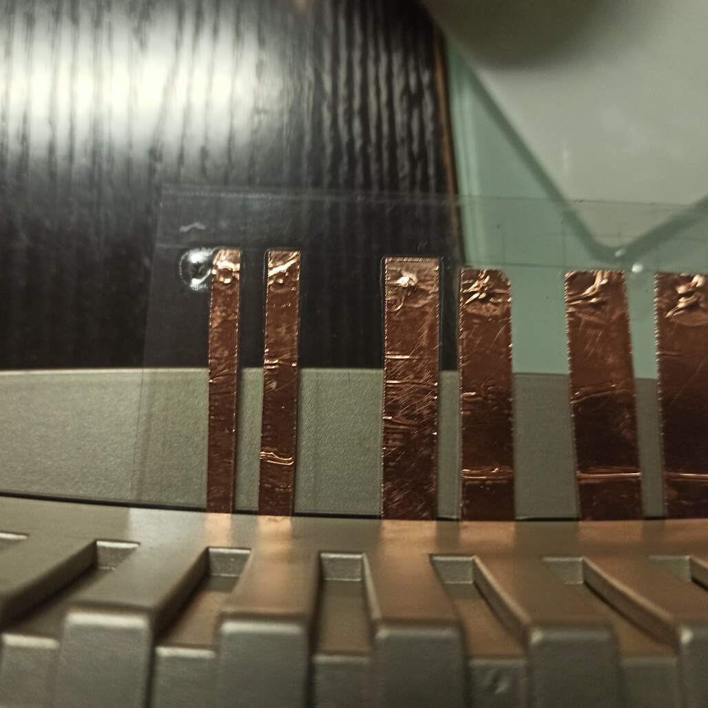
On this picture you can see the difference of the signals, when reading the load sensor (blue) and the transmit-receive sensor (red).

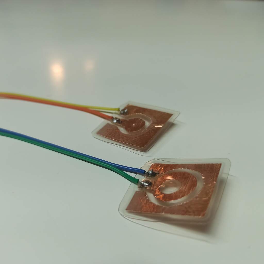
Also the third method that uses a RC circuit to sense the change on capacitance of the probe. For this I need to generate a square wave on the output pin and sense the voltage on the input pin.

To set up the square wave generation I use the timer/counter 0 on Clear Timer on Compare (CTC) Mode. And enable the Compare Output Mode to toggle on compare match for the OC0A pin. And set the OCRA to 0, to generate the highest frequency possible, and this setup you can change OCRA to modify the output frequency if needed.

Get the .cpp file

Troubleshooting

This week involve a lot of troubleshooting, I will explain how I solve the problems, to facilitate later debug and use of the capacitive sensors.

Main board issues

After I solder the board just before connecting it to the programming device I measure the conductivity between Vcc and GNC and found a short. I use visual inspection to found a place were the solder was bridging a GND trace to the outer copper, and Vcc was also bridged with the border, this can be solved by having more care when soldering or increase the offset setting on mods.

Then I connected the board to the ISP programmer and get the next error message

Confection error avrdude

to solved I unsolder the LED pull down resistor, to allow the MISO pit to be HIGH when the ISP communication is programming, but I receive the error again, then I found a short between the MISO and the VCC pins of the ISP header. After solving that the communication was established I didn't try to reconnect the LED yet.

Programming

When programming I found some issues, the first was the alternate pinout that is used when programming with the PlatformIO.

ATtiny44 pinout

The Arduino IDE with the ATTinyCore is mapped to a different pinout that the one used by PlatformIO (Alternative pinout).

Then the serial was connected the baud-rate was 1200, 8 times slower than programmed (9600), I forgot to change the internal Clock Prescaler (CLKPR) to 0, to obtain the 8Mhz clock signal.

Also on my schematic I connect the rx and tx pins so they end up diagonal on the header, but swapping the pines of tx when using the #define pin solved.

The final result!

On this video you can see how I tested the sensors.

Digital touch button 1 (blue)
Digital touch button 2 (red)
Level of water analog reading (green)

Conclusions

This week assignment was really fun, I really was intrigued with how capacitive sensors work since I was researching what kind of sensor may I use on my final project to measure soil moisture. I found that the most common Resistive sensor does not have a good use life, due to corrosion and oxide on the copper pads that are on direct contact with the moisture and soil.

On the oder hand the capacitive sensor can last longer because it measure the dielectric changes between dry and humid soil, without any part exposed to the moisture. I read that also it has less impact on the soil quality.

Have I?


Prev Next