Input devices
Group assignment
- Probe an input device's analog levels and digital signals
Using an oscilloscope
Digital signals
Here you can see a small test to probe digital signal sended from one Arduino UNO, it reassemble an almost square change from 0v to 5v, another microcontroller can 'sense' that as LOW/HIGH or 0/1. This type of signal is used on Serial protocols or true/false sensors.
You can also see a bit of noise on the signal, it can be introduced on the wires via capacitance coupling or inductance, but overall if it is over a threshold it will be considered as HIGH.
Jeffery Naranjo
For this week's assignment, two sensors will be used, the first a humidity sensor that can measure analog and digital signals according to the pin we use, and a motion sensor that gives us a digital signal.
Analog read
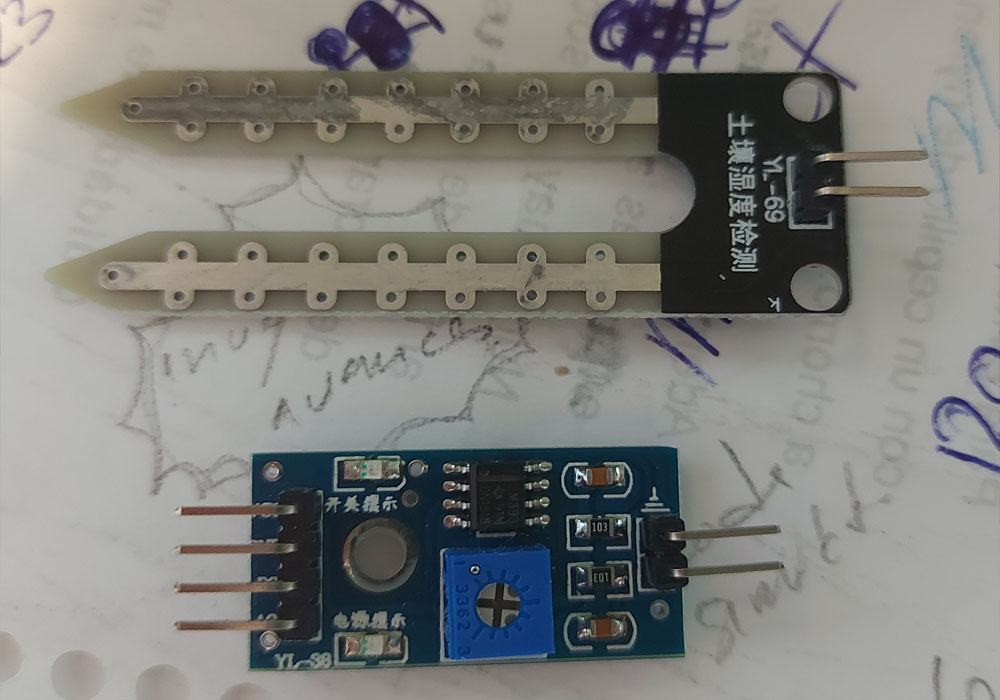
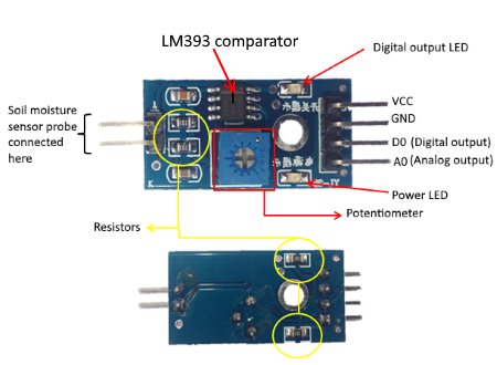
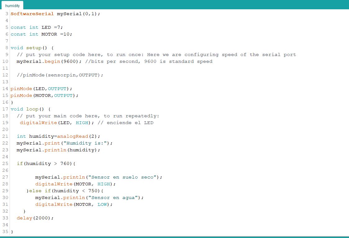
For the humidity detector we use pin A0 as analog output and connect it to pin 2 of our ATtiny 44
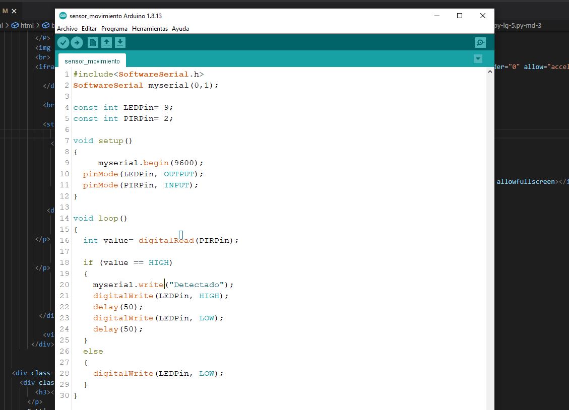
Digital read
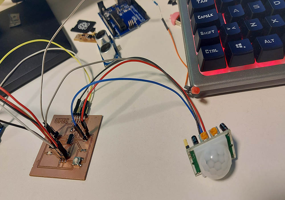
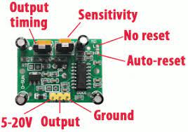 To read the digital signal we use a motion sensor HC-SR501 connected in the same way to pin 2 of our ATtiny 44
 For more information and to be able to download the files, I invite you to see the following link
INPUTS
For more information and to be able to download the files, I invite you to see the following link
INPUTS
Measuring signals with the oscilloscope
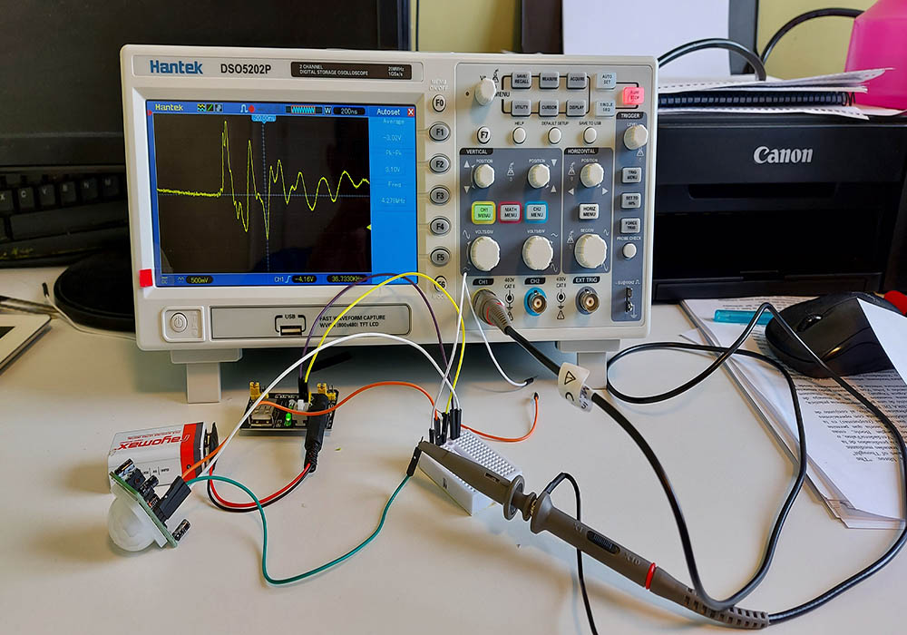
For the second attempt, we used a Hantek DSO5202P oscilloscope, and made the measurements of two sensors.
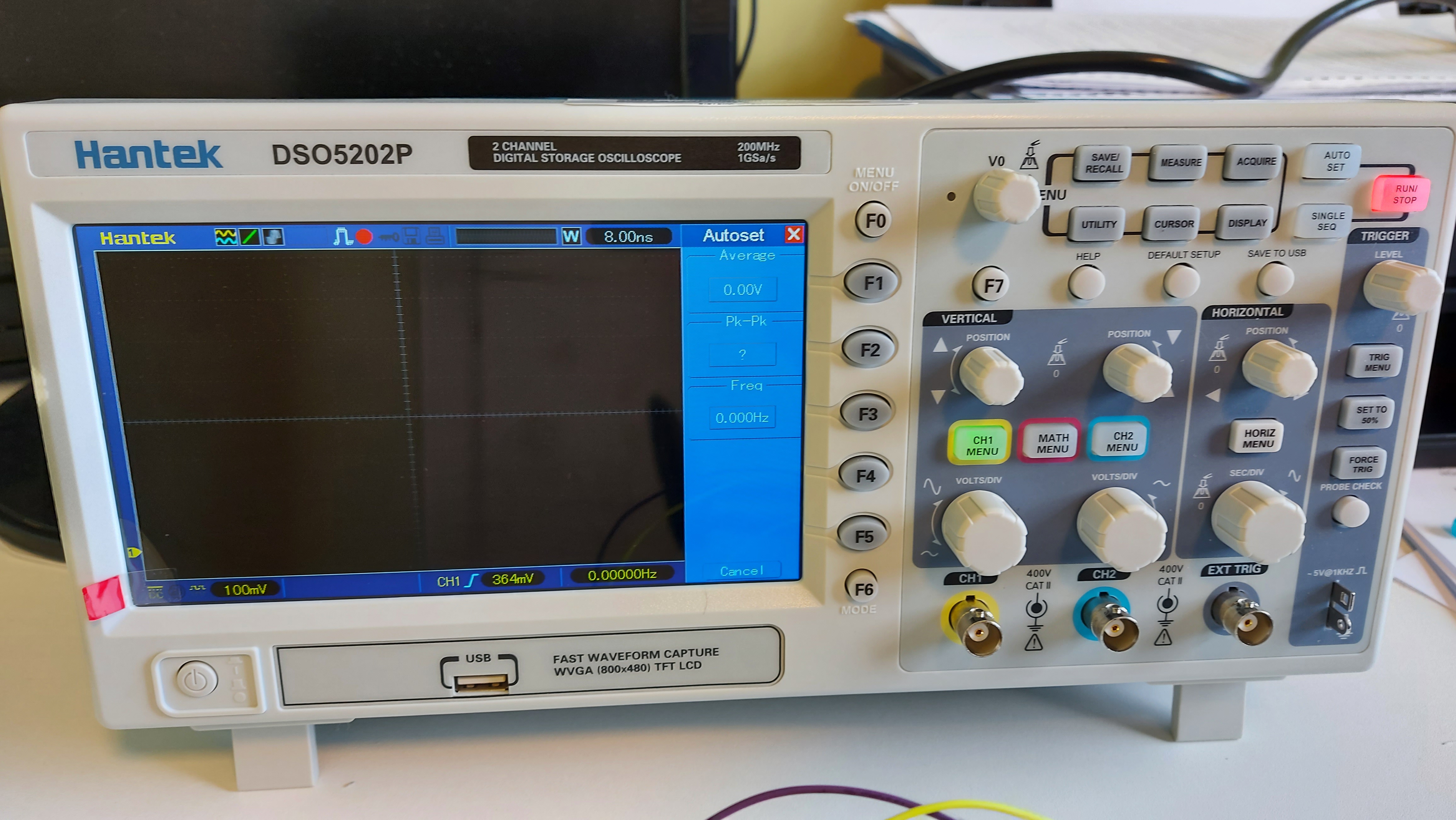
first we perform a test to verify the oscilloscope configuration by connecting to its own signal to make the necessary adjustments
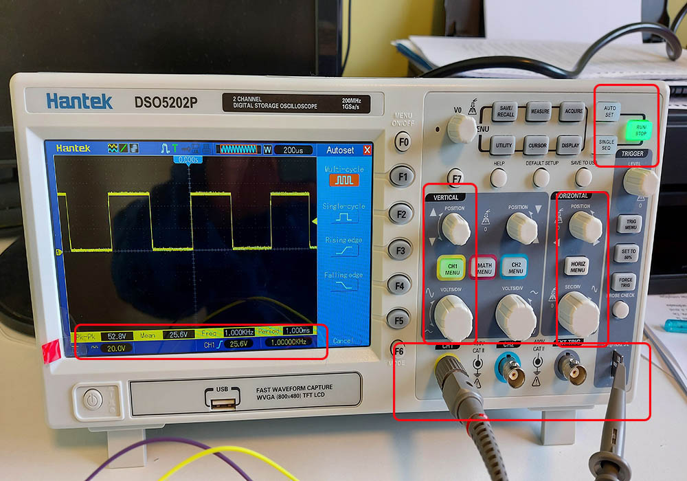
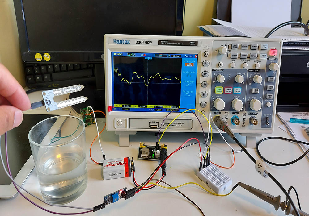
motion sensor
we connect a motion sensor to an external source and a 9v battery for its power supply and measure the sensor's output pin
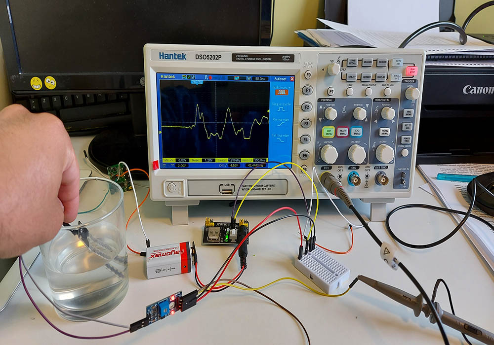
Humidity sensor
In the same way, we connect a humidity sensor and feed it to an external source and measure its digital signal with the oscilloscope.
Camilo Ortiz
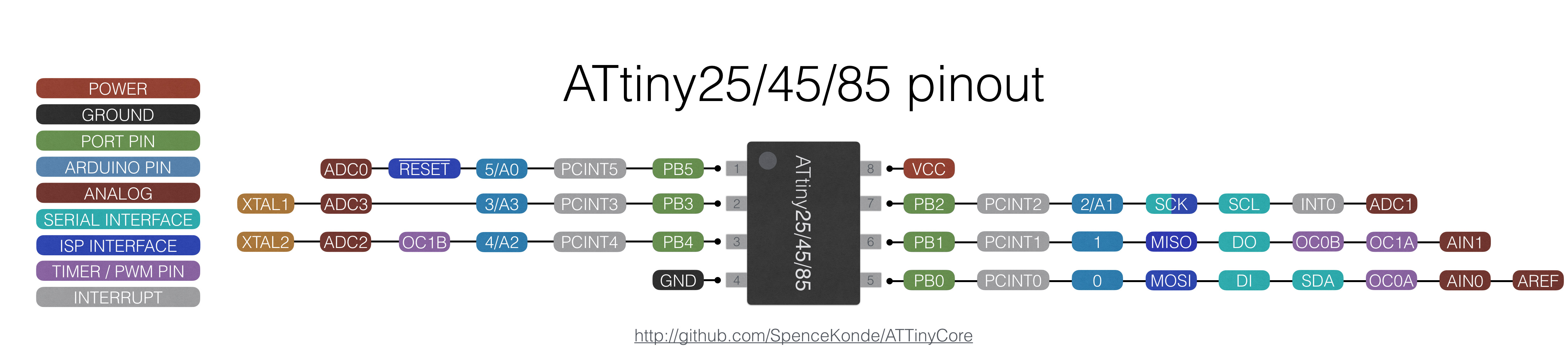
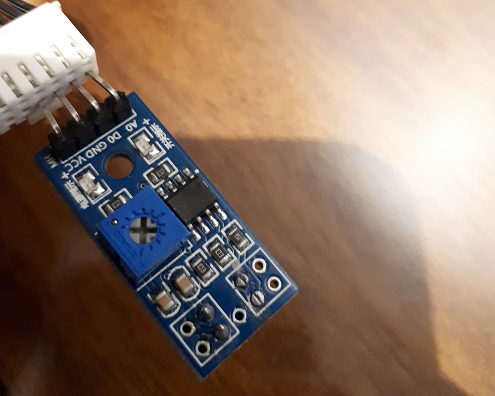
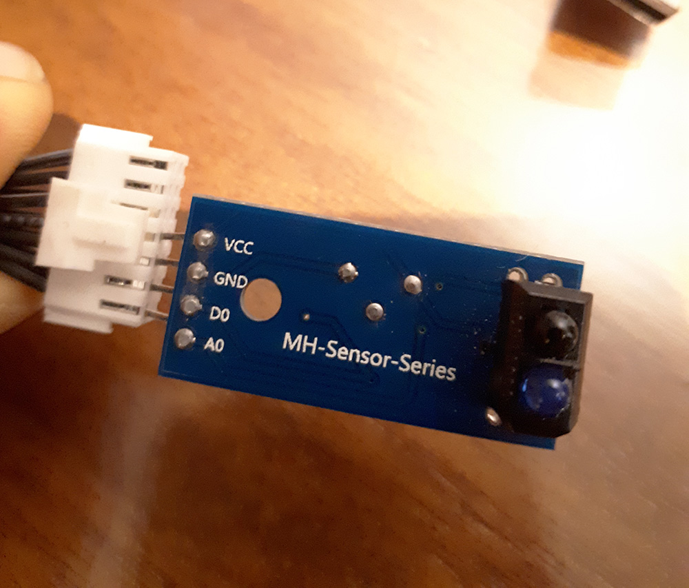
This week I decide to use the Attiny45 and a TCRT5000 Module which have an IR emitter and a phototransistor incorporated and can be use for some applications as detect white and black color (commonly used in line follower robot) distance detection (short distances), position sensor for shaft encoder and more. This module have an analog output and digital output so it's perfect to test and read from the same sensor both kind of signals.
Programming
Connecting the module pins, vcc, gnd and digital, analog signals to the board and the Tx, Rx pins from the board to Arduino, everything ready to read the values. This module have a potenciometer to calibrate the sensitivity of the digital signal to change from one to zero. This can be usefull if you don't need to map the analog values, in other words, show data to the user to be read as distance. It's also important to notice using analog signal will be always more precise than a potenciometer calibration in this module and could be cases is needed to detect different positions of an object and not just care obout a "border line" in this cases will be convinient read an analog signal.
Serial Read
Once everything is programmed and connected it's time to read the values
You can find the original files and more details on my personal Week 10 Assigment page
Daniela Felix
You can find further details of my work with digital and analog modes on my site:
Input devices
Arduino Serial Plotter to Compare Analog and digital signals
To understand how the signals are correlated I use one of my capacitive touch sensors, (you can see more here) and program the microprocessor to send via serial port the row value and a 'digital' that is compared with a threshold value.
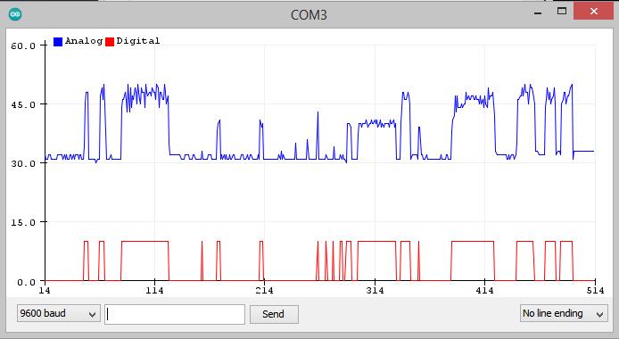
As you can see using a threshold value you can make digital sensor output when you need only a true false reading.