GROUP ASSIGNMENT
Find out the details of our common work al ZOI
Here.
Planning
This was an atypical week in the laboratory, since the covid situation has become complicated in Quito. Because of this we decided that each one of us
would do their exercises at home and share these results online.
In my case, this is still a demanding topic, so I followed some tutorials to use arduino. As part of my final project, I will integrate a soil humidity
sensor and another one for humidity and environmental temperature, both of great use to preserve the environmental conditions of the compost bin.
Based on this, I decided to test analog and digital communication with one of these sensors.
Soil moisture
Soil moisture is the water stored in the soil and is affected by precipitation, temperature, soil characteristics, and more.
Solids, liquids, and gasses, the three phases of matter, are always present in soil. Small mineral and organic particles comprise the solid fraction,
and there are spaces (pores) between the solid particles. Some pores are large, and others are very small. Air and water, the gas and liquid phases,
exist in the pores. The size of the soil particles and pores affects how much water a soil can hold, and how that water moves through the soil.
Soil moisture sensor
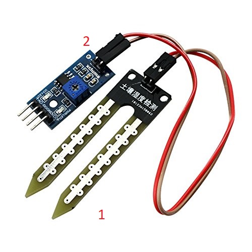
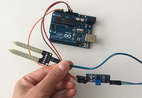
A soil moisture sensor has many applications, especially in agriculture. The one I am going to use is the following, which comes in two components:
the #1 first one has 2 male headers, that can be interfaced with the blue board using the Female to Female type jumper wires or soldered to these pins.
The second one #2 is an amplifier/ Analog to digital converter circuit. This circuit is connected with the Arduino using these 4 male headers. These 4 male
headers are labeled with Vcc. Ground, D0 and A0. D is for the digital and A is for the analog, this means it can get values in both Digital and Analog.
The digital output is in the form of 0 or 1which can be controlled using this potentiometer.
This module has also two led’s, one led is the power ON led, while the other led works with the digital output pin. When the moisture is below a certain
value which is set using the potentiometer then led remains off. When there is moisture, this led turns ON.
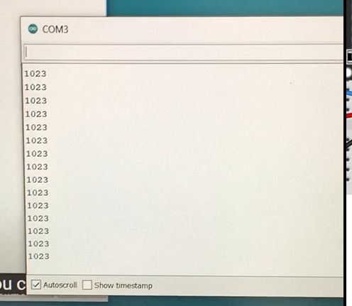
While the analog output can be any number between 0 and 1024. This value will entirely depend on the water content present in the soil.
 *This picture was taken from Amazon
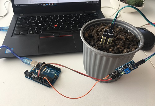
This was the first time I tried Arduino on my own, so I had to follow some basic steps in order to set everything. The following link was really helpfull
conecting the Arduino to the usb port and running Arduino IDE. Arduino first steps
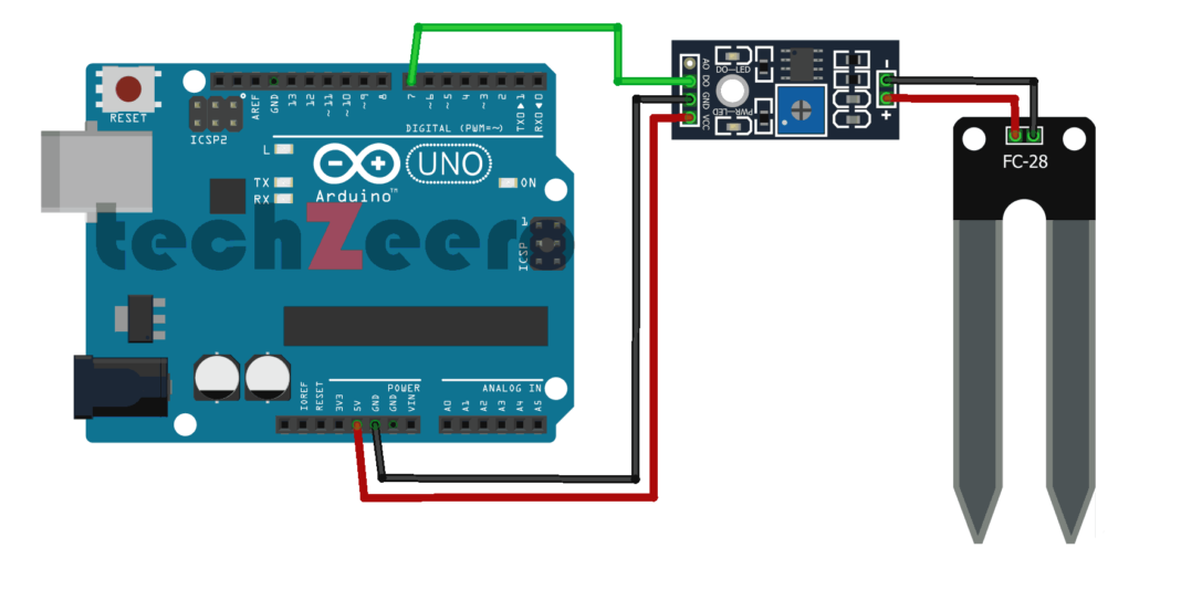
Connecting the component to the arduino for ANALOG MODE
To understand this point is very helpfull to look at the component pinout.
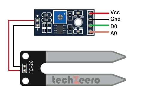
The following diagram shows how to connect the component to the Arduino and the process of doing it by myself.
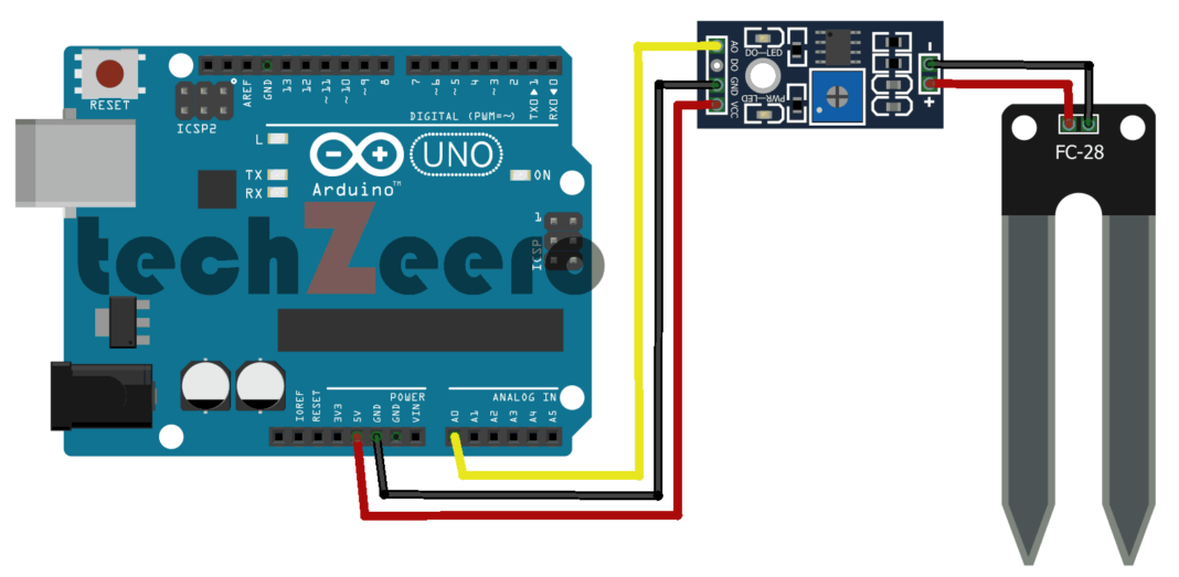
*This pictures and information was taken from techzeero
The next steps were esasy to follow, once everything was connected I uploaded the code, using Arduino IDE:
/*
Soil Moisture with Arduino - Analog Output
*/

int msensor = A0; // moisture sensor is connected with the analog pin A0 of the Arduino
int msvalue = 0; // moisture sensor value
int led = 13;
boolean flag = false;

void setup() {
  Serial.begin(9600);
  pinMode(msensor, INPUT);
  pinMode(led, OUTPUT);
}

void loop() {
  msvalue = analogRead(msensor);
  Serial.println(msvalue);

  if ( (msvalue >= 500  ) && ( flag == false ) )
{
  digitalWrite(led, HIGH);
  flag = true;
  delay(1000);
}

  if ( (msvalue <= 300  ) && ( flag == true ) )
{
  digitalWrite(led, LOW);
  flag = false;
  delay(1000);
}

  delay(1000);
}
what I understood from this exercise: is the msvalue (what I am receiving from the sensor) is higher than 500, the led TURNS ON,
this means the system needs water, the flag=false turns to true. Then if I add water, the ms value is less than 300, the les TURNS OFF,
this means the system is ok and the flag turns to false. You can see this in the following video:
Connecting the component to the arduino for DIGITAL MODE
In this case is necessary to change the pin on the arduino, the following diagram shows how.
Then the code for this is:
/*
Soil Moisture with Arduino - Digital Output
*/


int msensor = 4; // moisture sensor is connected with digital pin4 of the Arduino
int led = 13;
boolean flag = false;
void setup() {
  Serial.begin(9600);
  pinMode(msensor, INPUT);
  pinMode(led, OUTPUT);
}

void loop() {


  if ( (digitalRead(msensor) == HIGH  ) && ( flag == false ) )
{
  digitalWrite(led, HIGH);
  flag = true;
  delay(1000);
}

  if ( (digitalRead(msensor) == LOW  ) && ( flag == true ) )
{
  digitalWrite(led, LOW);
  flag = false;
  delay(1000);
}


  delay(1000);
}
what I understood from this exercise: in this case the results are much simplier, kind of a yes no answer determined on the levels
I set for the measurement.
Also, this are the web site that helped me troughout the process:
How to connect to the arduino
Code for analog and digital mode
Humidity and temperature sensor
The component I used for this practice is the DHT11 humidity and temperature sensor, recommended for remote weather stations, home environmental
control systems, and farm or garden monitoring systems.
Here are the ranges and accuracy of the DHT11:
- Humidity Range: 20-90% RH
- Humidity Accuracy: ±5% RH
- Temperature Range: 0-50 °C
- Temperature Accuracy: ±2% °C
- Operating Voltage: 3V to 5.5V
Also the date sheet for further information:
DHT-11
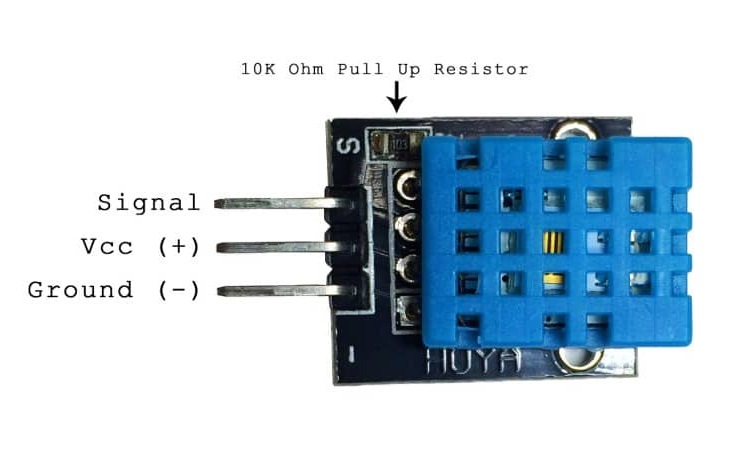
The following diagrams shows how to connect it to the arduino:
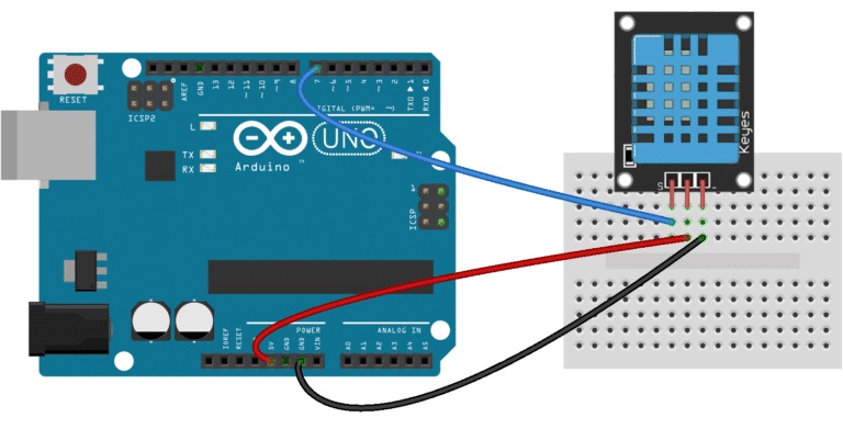
*This diagram was taken from:
Programmer click
I needed to install an arduino library avaliable in this link:
dht.h
The code I used for this exercise:
#include

dht DHT;

#define DHT11_PIN 7

void setup(){
  Serial.begin(9600);
}

void loop(){
  int chk = DHT.read11(DHT11_PIN);
  Serial.print("Temperature = ");
  Serial.println(DHT.temperature);
  Serial.print("Humidity = ");
  Serial.println(DHT.humidity);
  delay(1000);
}
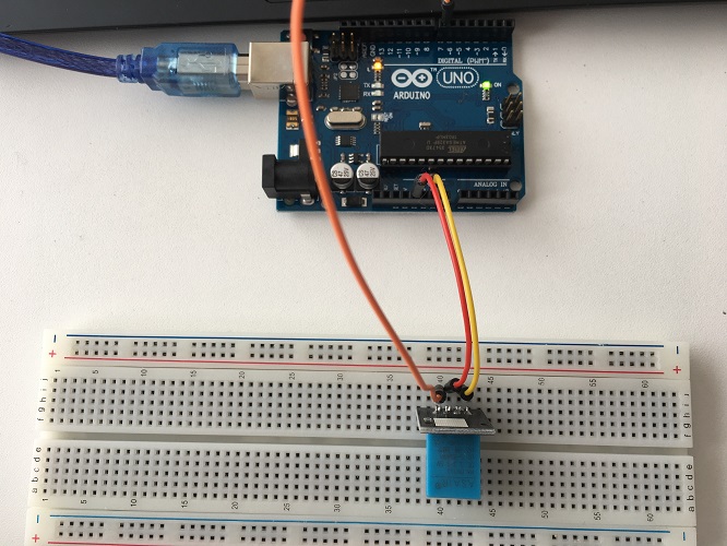
You can see my results in the following video:
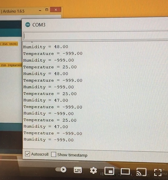
What I learned from this exercise: with the code I used I'm getting values for both temperature and humidity, they are still
kind of hard to understand because of the values. Later, in outputs week I connected my sensor to an lcd screen to show the data,
I encourage you to visit this exercise in the next link to know about the details:Outputs week
What I learned with this exercise:It is finally starting to be fun, at this point I feel I get a better understandig
little by little, and in a way my final project seems to see some light at the end of the tunnel.
For some more details about this process you can go to this site were I took the code and instructions from:
Humidity sensor and LCD
Many ways to code the LCD
INPUT DEVICES
After having some fun with Arduino I started designign my own input board. In order to do this I based my design on the satsha kit.
A satshakit is a **100% Arduino IDE and libraries compatible**, fabbable and open source board, and also an improved version of the Fabkit.
Main **improvements and features** over Fabkit are:
- **16Mhz** instead of 8Mhz
- **crystal** instead of resonator
- **costs less** (7-9 euro vs 13 euro)
- 100% compatible with **default Arduino IDE** (satshakit is recognized as Arduino UNO)
- ADC6/7 connected instead of ADC6/7 not connected (satshakit laser and cnc)
- larger space to easy soldering (satshakit laser and cnc)
I found out that there are many versions of the satsha kit, but following the steps of Nagi-abdelnour a former student from 2019
and I managed to do my own board.
In the following links you can find the information useful for the satsha kit, download the files and read further information.
Satsha micro
Satshakit
Very important to have on mind when designing, the pint out of the ATmega328P-Au which I chose to work with, and the arduino pins that correspond.
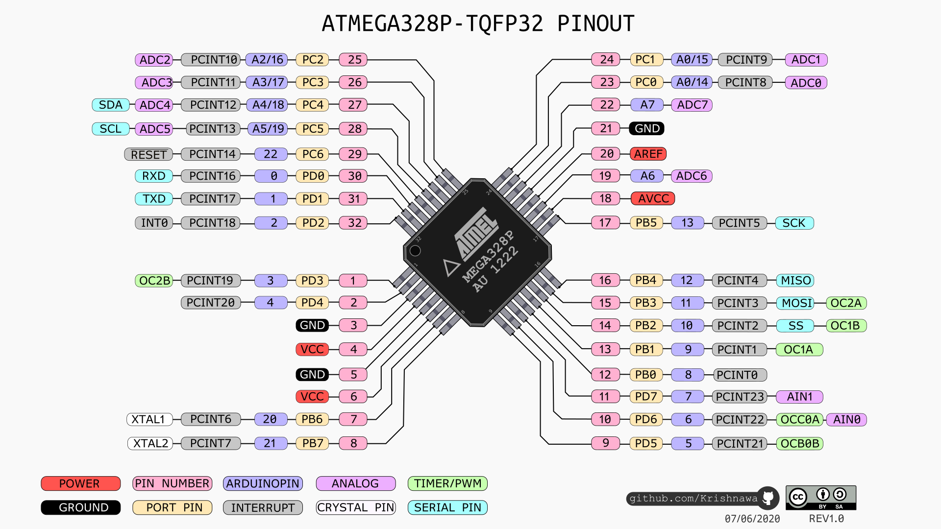
*This picture was taken from: Redd
DESIGN ON EAGLE
The sensors I plan to use with my board are:
- FC-28 Soil Moisture sensor
- Temperature and a humidity sensor – DHT11
I had to reinstall Eagle on my computer and so the fablibrary as well, this are the steps to follow to do it:
- First download the Fab Library containing the components we'll be using for the class.
- Copy the fab.lbr file into the libraries folder of Eagle
- Open Application-> Eagle -> Lbr and add the downloaded Fab Library.
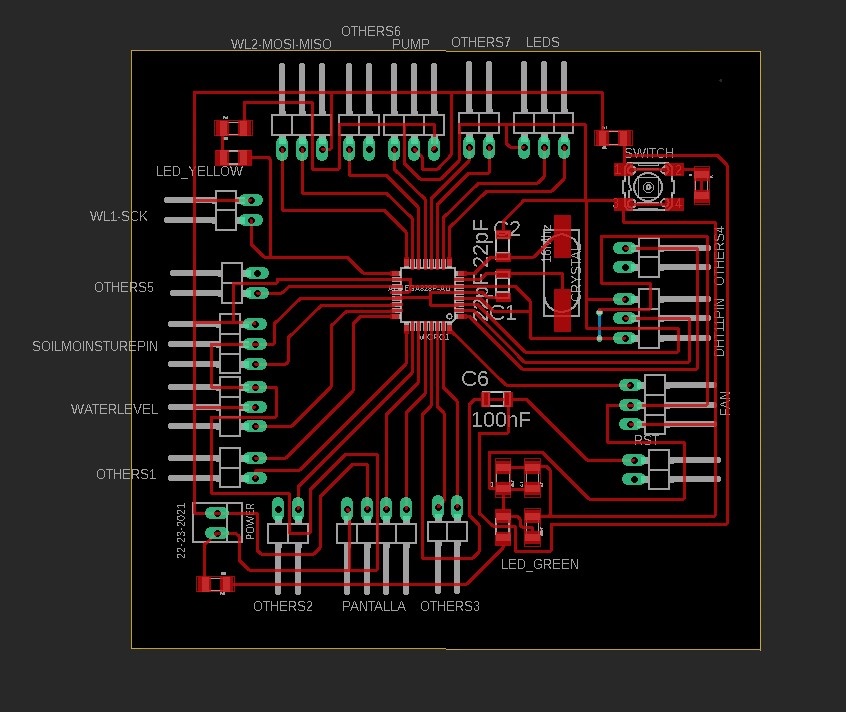
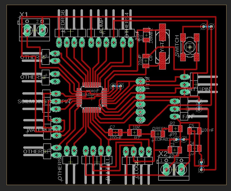
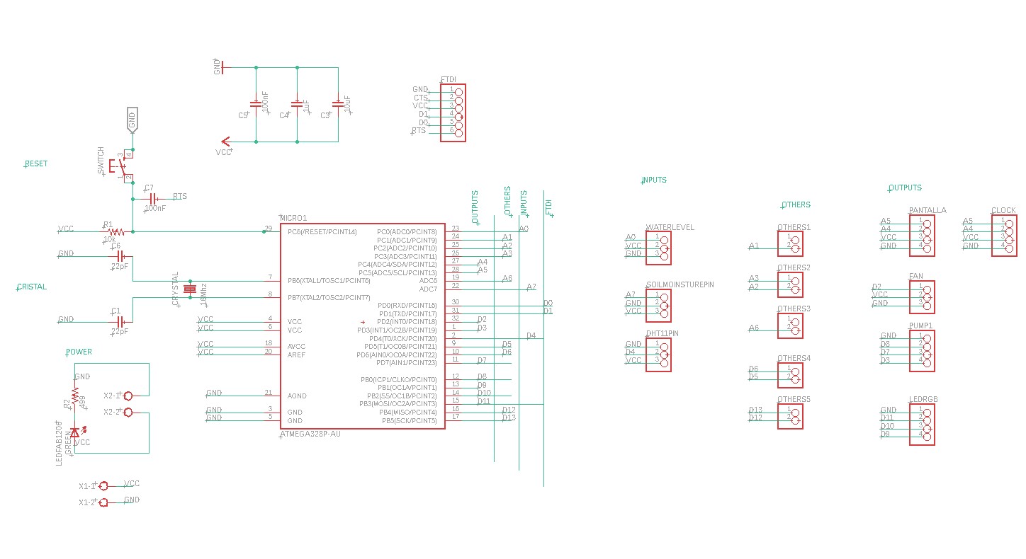
Worked on the schematic, and this is the result:
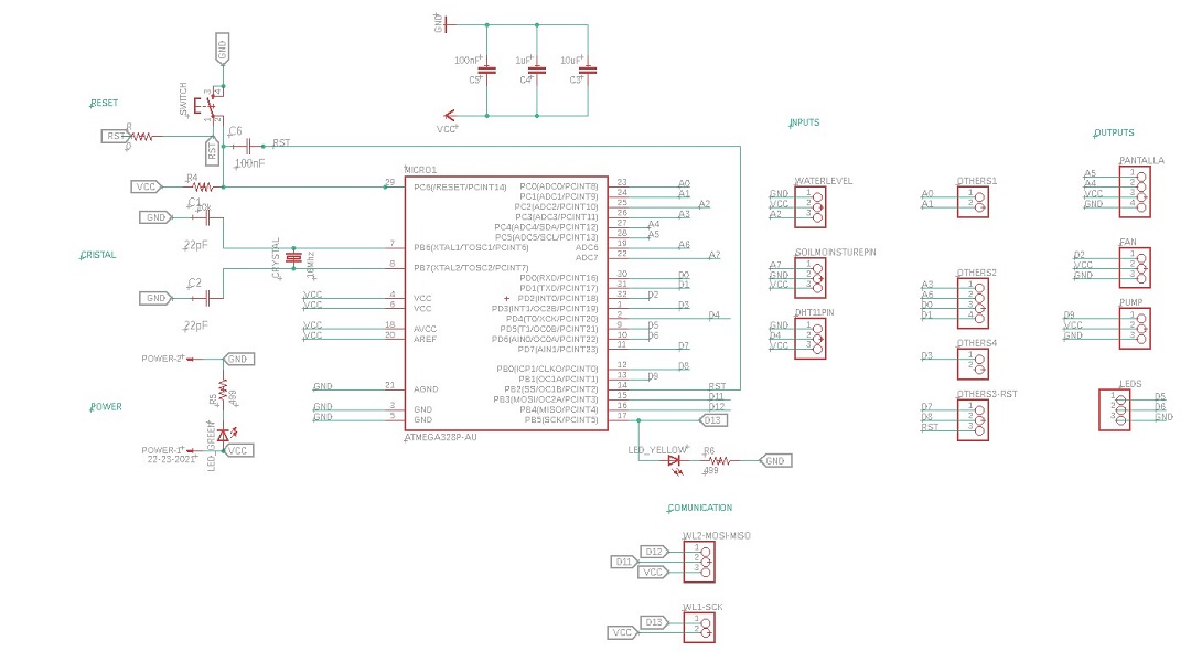
My tutor suggested that I connect all the pins available for the mic, plan that it can be used for multiple functions and leave the pins that were not being used for
other possible uses if necessary. It was a challenge to connect everything, but I enjoy this process at Eagle, I find it relaxing and challenging to order all the
components with minimal drilling.
Worked on the design board, this is the result. After running the design check there are no mistakes.
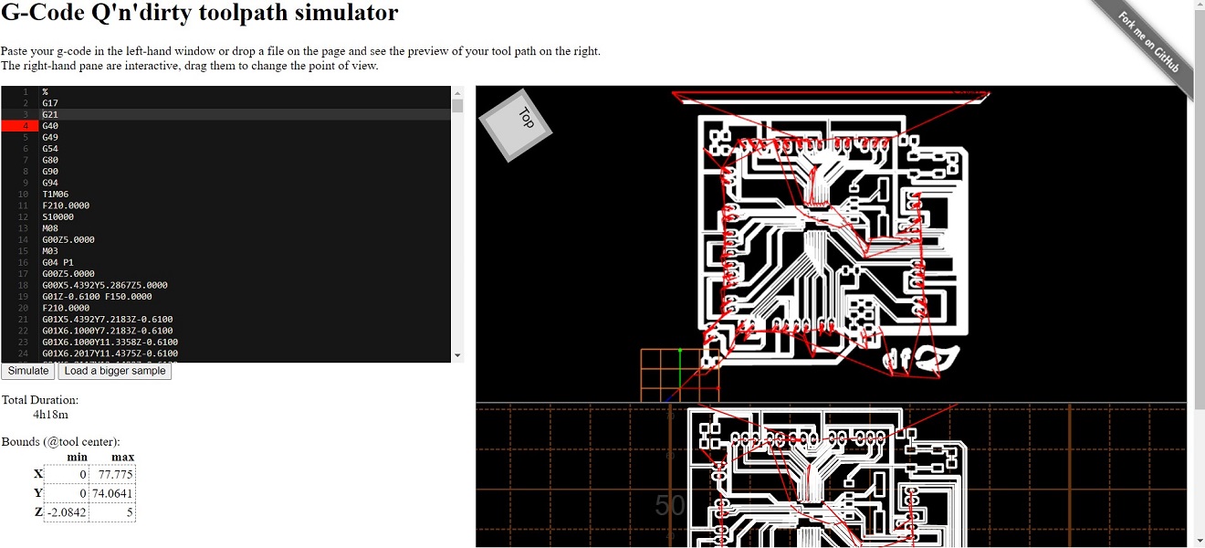
Worked on generating the code, this is the result on the simulator:
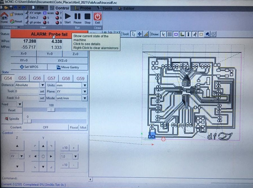
Then I went to lab to do mill my board and something didn't work with the machine, this error kept coming out over and over again.
So my tutor and I decided to make a pause in this process, check again the design board and come back to produce it another day.
Fortunately I did not do it that day as the design was still buggy.
Diego helped me checking my board design and suggested some changes that will improve the performance of it and also helped me
add some components I was mising, for example, I had many doubts on how to connect the rest of the pins I wasn't using, also added a terminal block.
This is my new schematic and board:
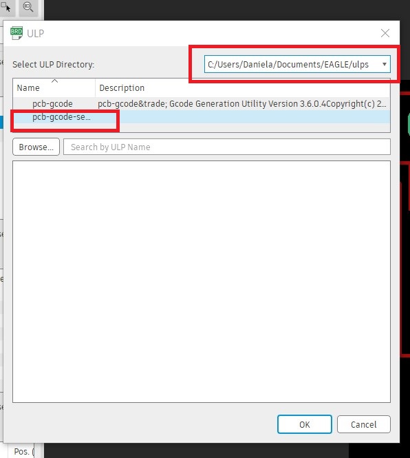
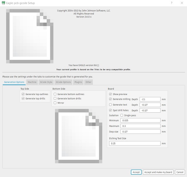
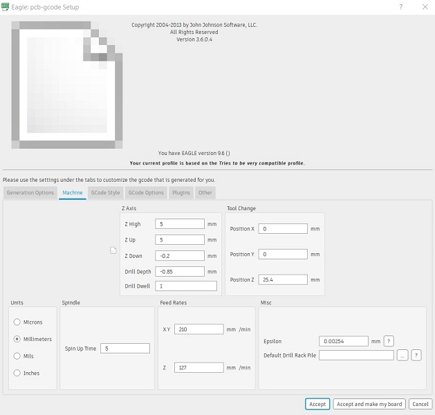
To generate the Gcode I used ULP with the following parameters, remember that it is necessary to install the ULP first and upload it
from the ULP directory located in the EAGLE folder on Documents:
FILES
Eagle board and schematic
GCode
PNG traces
PNG contour
Components
In this case I'm going to use:
- 1- Micro 328P-AU
- 1- Crystal 16Mhz
- 6- pinheads for the FTDI
- 3- C 1uF. In the schematic there are 2 100nF Capacitors, which are not avaliable in the lab so I changed them to 1UF capacitors
- 2- C 22pF. Also not avaliable at the lab so I soldered 2 10pF capacitors, one on top of the other to achieve 20pF
- 1- C 10uF
- 1- R 10K
- 1- R 499Ω
- 1- Led green
- 1- switch boton
- 26- pinheads for the sensors
- 2- screw Terminal Block: 2-Pin, 5 mm
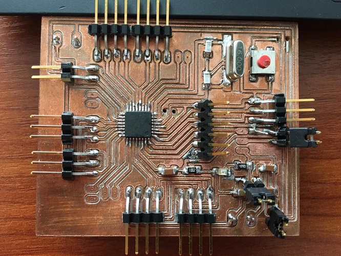
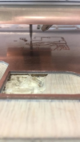
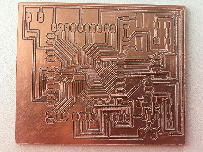
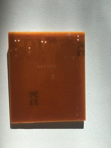
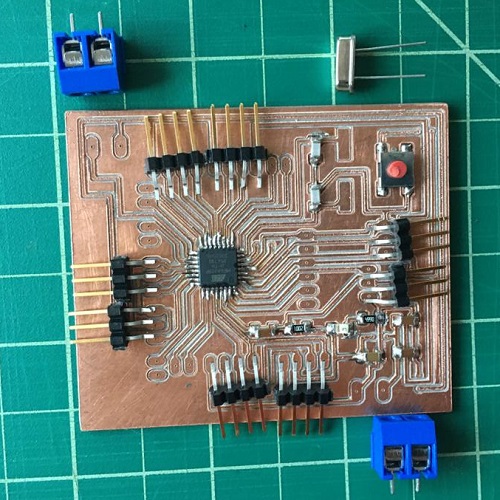
Here some pictures of my board:
To place some components, holes were needed in the board, for which I used a dremel. This is the result:
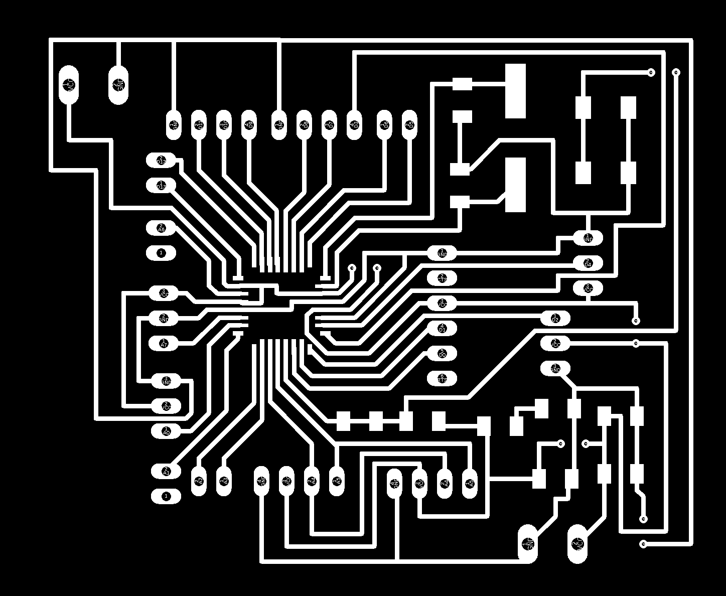
Some thoughts about his outcome
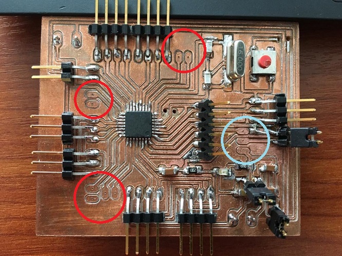
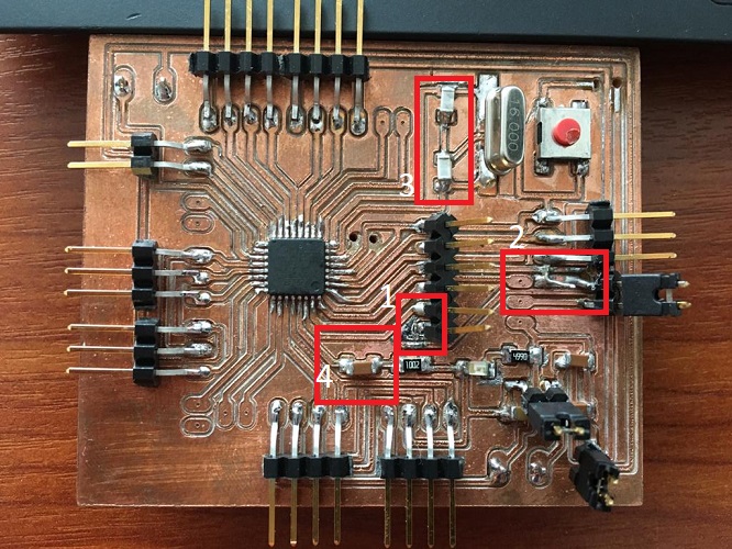
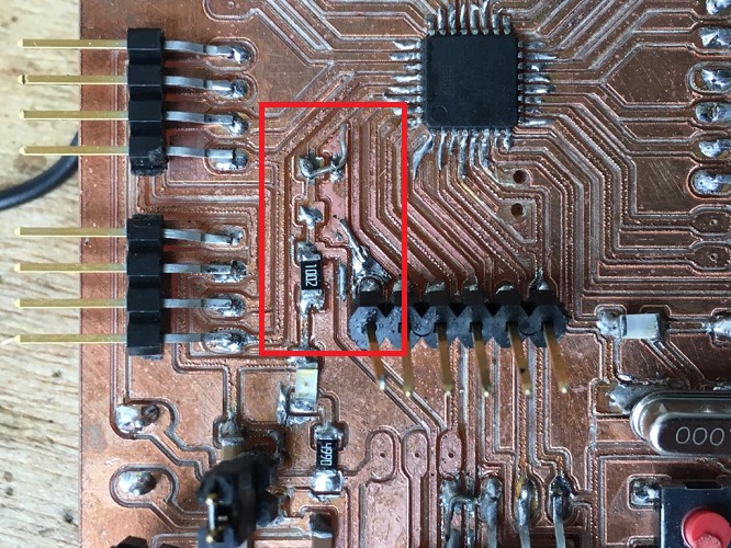
The following picure shows that I didn't solder all the pins that were on the schematic. I found it unnecessary since they were pins that had no function
(those marked in red). The blue circle shows an error in the design, fortunately I did not have a component to connect in that place, otherwise it would have been
impossible to place it since there is no space available for the pins.
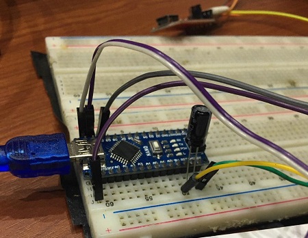
PROGRAMMER AS ISP
Once all the components were soldered, I made the connections according to the suggested satchakit scheme:
I am planning to use Arduino to program mi board, since is the one I understand better. Followed the instructions of the satcha web site:
- Open Arduino IDE
- Select proper programmer (for example Arduino as ISP or USBtinyISP)
- Select Arduino UNO as board
- Click on tools->Burn Bootloader
Something is not ok with my board, seems to be a shortcut. Need to find where is the problem.
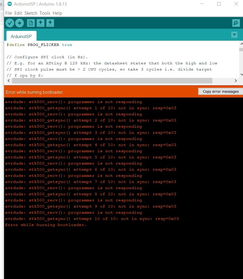
DEBUGGING
💔
These weeks of debbunging reminded me of the recitation in electronic design week where they said "Debbugging:
being the detective in a crime movie where you are also the murderer".
Although we reviewed with Diego the schematic, the board, the welding process, voltage, continuity in the tracks, my board could not be programmed,
it doesn't even turn on.
The first reccomendation was to have a positive attitude about this process, but it could be really frustrating, there are so many possibilities
which can make this not to work. Following the general principles to start narrowing the problem we followed the next steps:
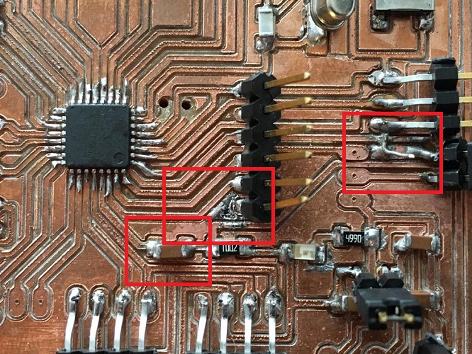
- Visual check: traces, solder, components: Turns out all of them had problems. Starting on the schematic, (1.) I misspell RST and one pin of the FTDI
wasn't connected, so we improvised and weld it to the closest trace avaliable. (2.) While soldering I missed a VCC trace that was too close to another one,
in this case we also had to weld it to the closest one. (3.)I was suggested to use 2 (10pF) capacitor instead of 1(22pF), which also seemed to be causing problems,
I had to unsolder the ones that werent working and place the new ones. (4.)Also, had troubles with the Reset capacitor, I had to remove it and make a bridge
At this moment my boards starts to look like Frankenstein. But finally it turns on!!
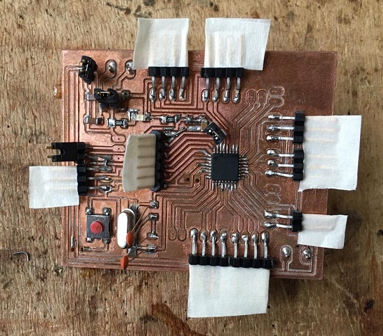
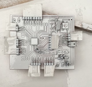
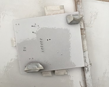
- Diego recommended me to paint my board to keep the traces safe (after this recostructive surgery that we had done). Had to put some tape on the piheads and used
matte white spray paint on both sides.
ARDUINO AS ISP - HOW TO BURN THE BOOTLOADER
Now that it finally turns on, we had some trouble uploading the bootloader it. We found this web site that finally led us to a solution, since the
satsha instructions weren't working.
Based my process on the information available in the following link:
ATmega328P-AU bootloader
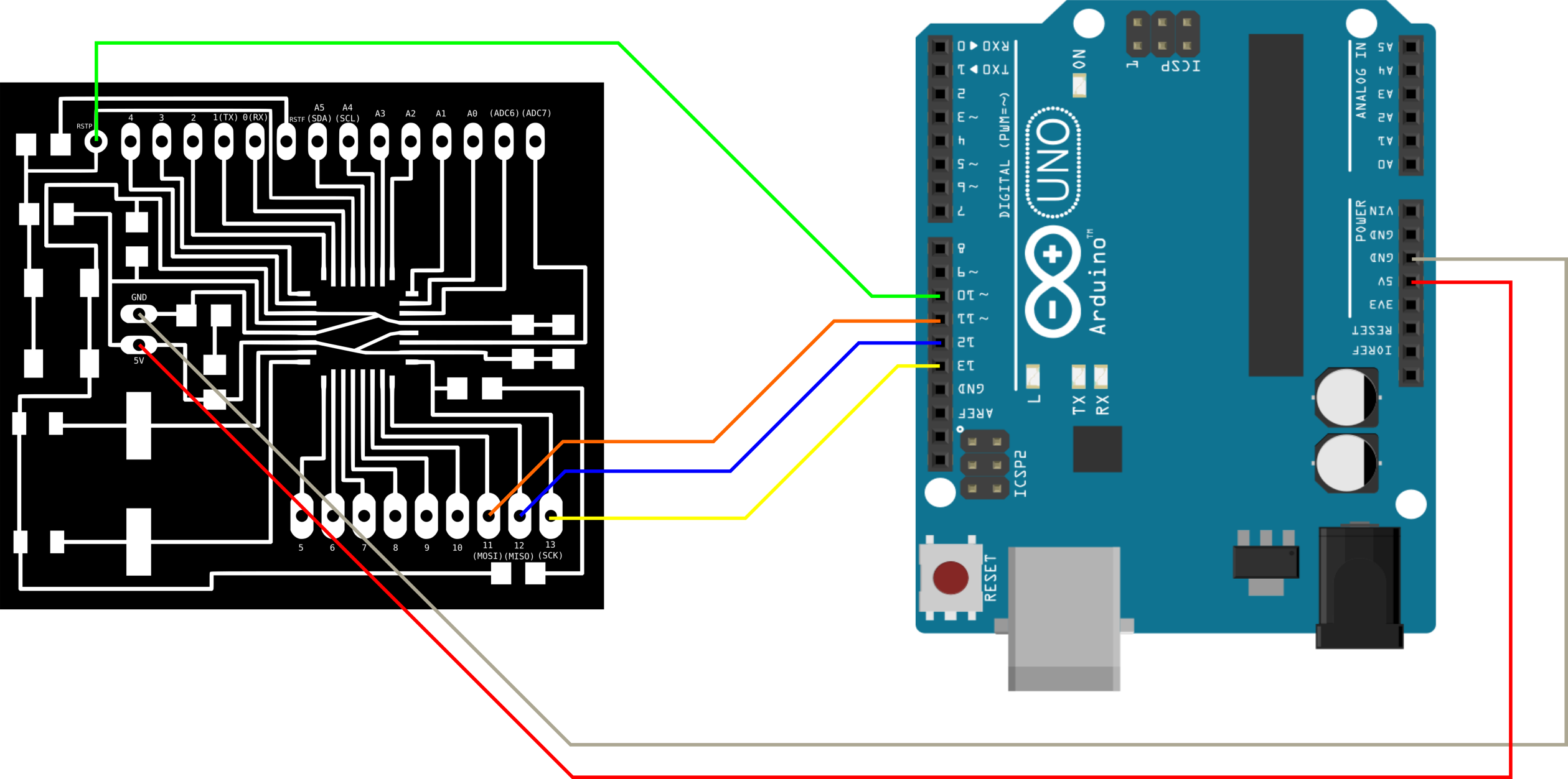
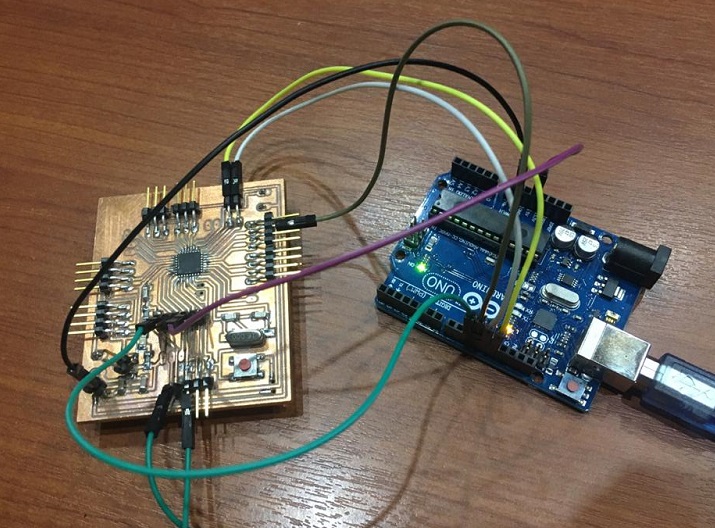
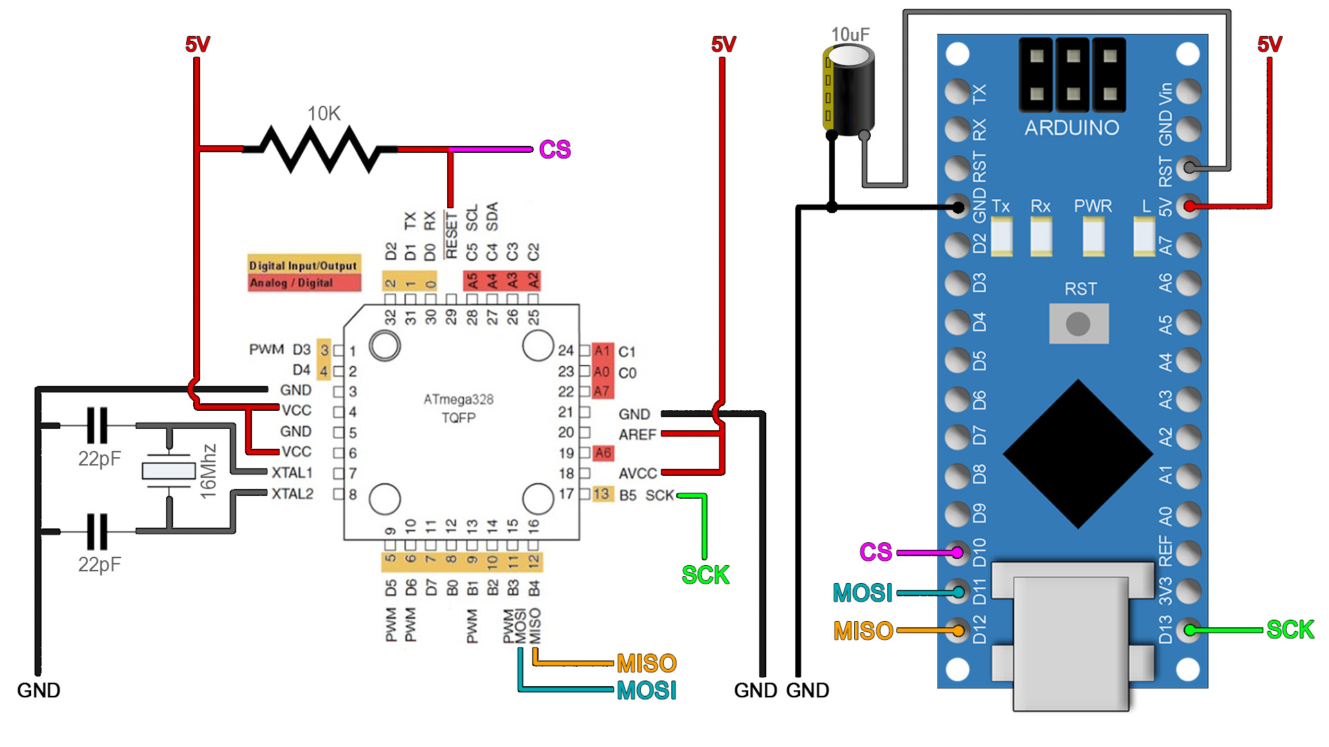
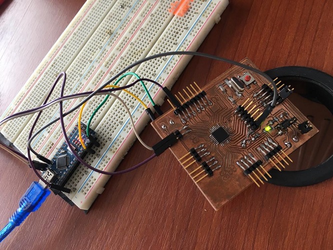
1. CONNECTIONS
Connect your board to the Arduino Nano:
| MICRO |
ARDUINO |
| CS (Reset) |
D10 |
| MOSI |
D11X |
| MISO |
D12 |
| SCK |
D13 |
| GND (connected to the terminal block) - |
GND |
| VCC (connected to the terminal block) + |
5V |
2. ARDUINO as ISP
We need an Arduino NANO to burn the bootloader. As the following diagram suggests, I added the 10uF capacitor connected to GND and RST, but it wasn’t working.
So we tried again without the capacitor.
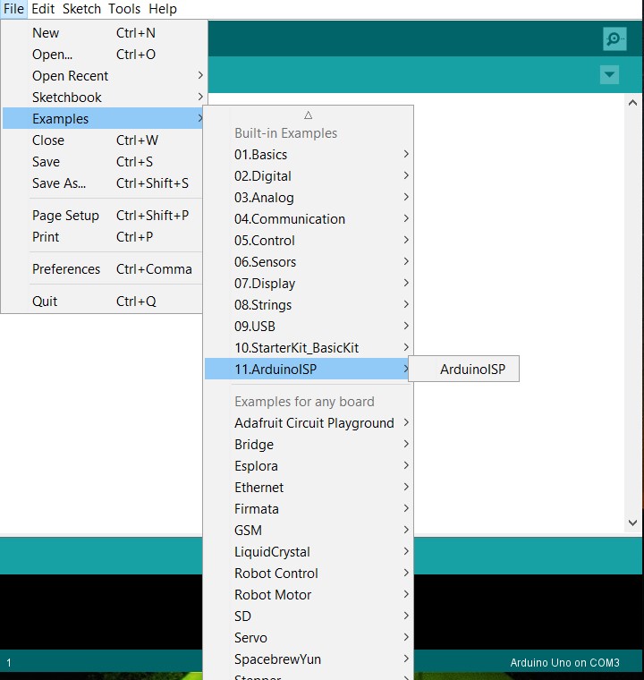
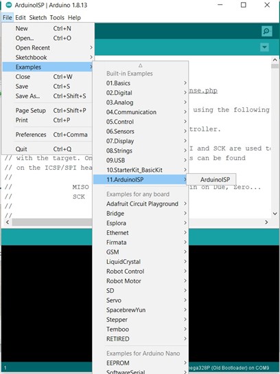
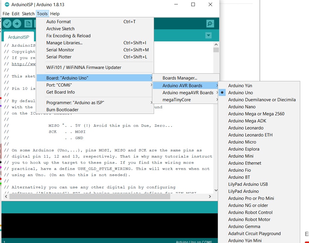
3. ARDUINO IDE
Follow the next steps:
- Go to examples > Arduino ISP > Arduino ISP
- In tools:
- Board:Arduino Nano
- Processor: AtMega328P(Old bootloader)
- Port:COM… (select the port recognized)
- Programmer: AVRISP mkll
- Upload the code: click on verify and upload
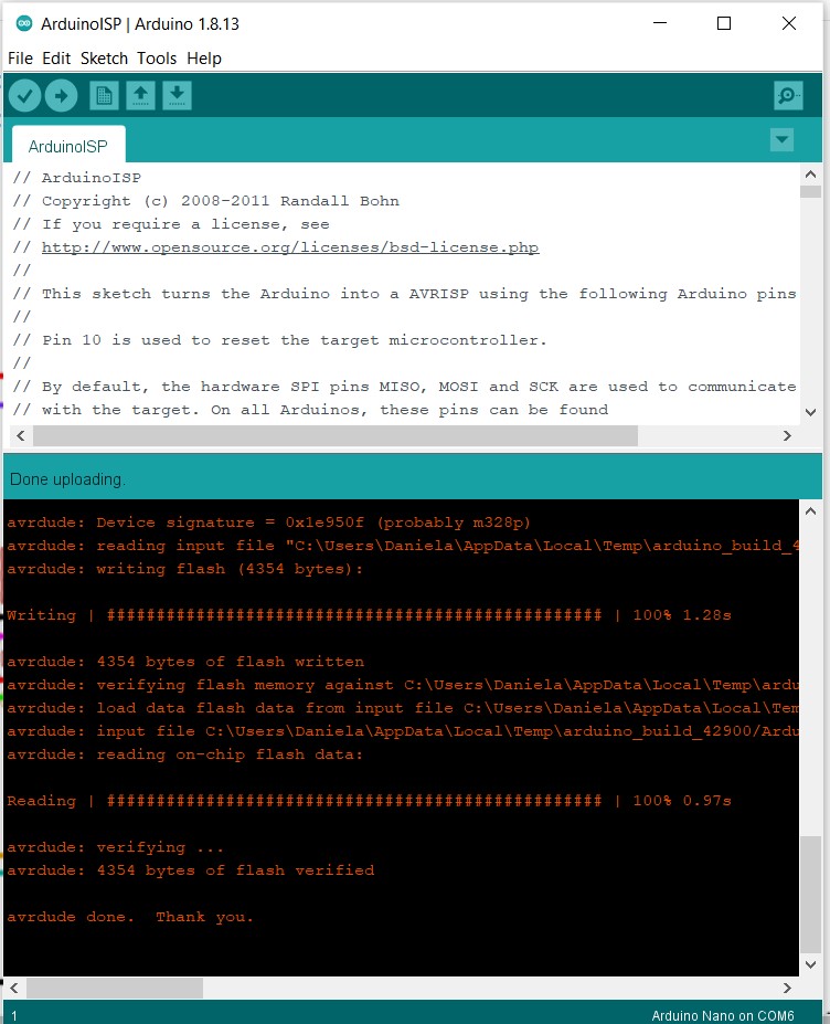
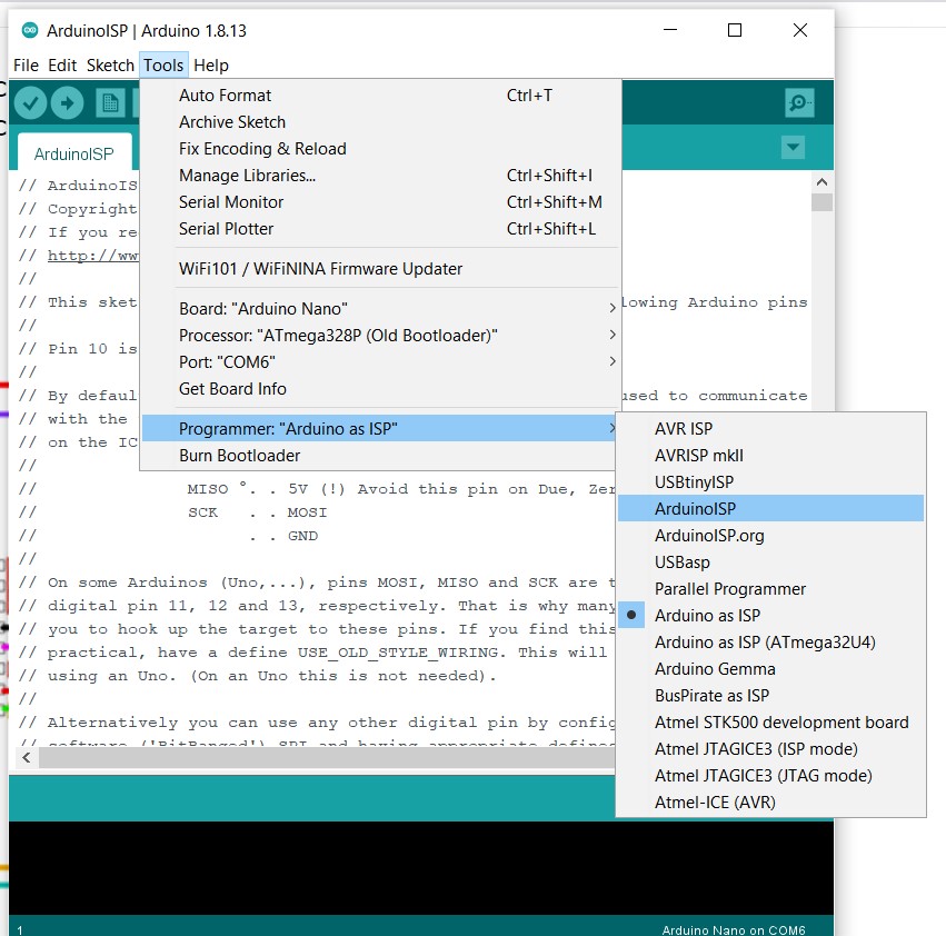
4. BURN THE BOOTLOADER
Now is time to add the capacitor to the equation:
Back to Arduino IDE, go to Tools:
- Board:Arduino Nano
- Processor: AtMega328P(Old bootloader)
- Port:COM (select the one you are using)
- Programmer: Arduino as ISP
- Burn Bootloader
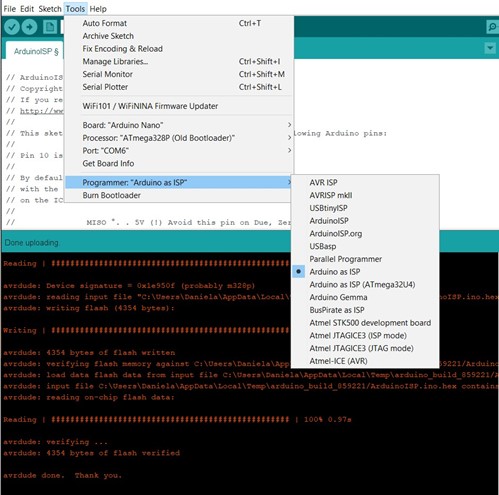
Once this is ready this message will come up:
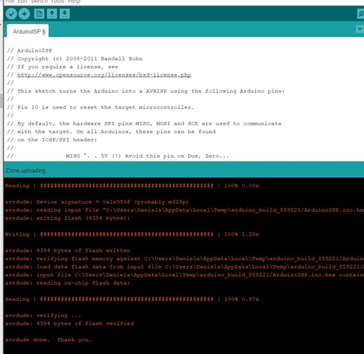
5. UPLOAD THE CODE
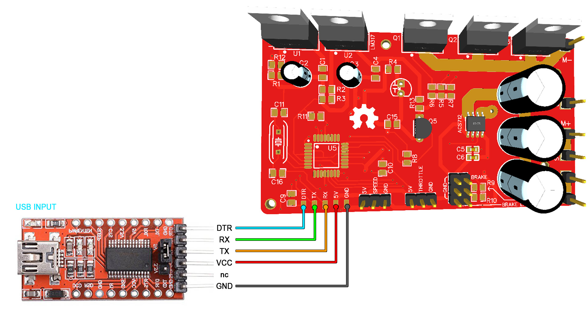
Follow the next steps:
- Connect the FTDI to the programmer, it is important to remember that RX goes to TX
- Open Arduino IDE
- Make sure the pins of the module you want to use are correctly connected, in this case I used a RGB led wich uses:
- D9 (was the same pin used for MOSI, make sure both pins are connected now)
- D10
- D11
- GND
- Load the code
- Verify
- Upload
Programming my board
For my final project I plan to use a humidity and temperature sensor, so I'm tryning to use it and program it with my board.
It is really important to remember that RX has to be connected to TX and TX to RX, otherwise you might experience problems.
Also, keep in mind that the pins on the Arduino are different from the ones on the micro, so be aware of this on the code.
I used the DHT11 and the code from this site:
How to set up the DHT11 humidity sensor on an arduino
Install the DHT library avaliable on the same web site. And, this is the code I used to test this sensor:
#include

  dht DHT;

  #define DHT11_PIN 4

  void setup(){
    Serial.begin(9600);
  }

  void loop(){
    int chk = DHT.read11(DHT11_PIN);
    Serial.print("Temperature = ");
    Serial.println(DHT.temperature);
    Serial.print("Humidity = ");
    Serial.println(DHT.humidity);
    delay(1000);
  }
Finally, some data from the sensor using my board.
PROGRAMMING WITH THE ISP PROGRAMMER
DTH11 - TEMPERATURE AND HUMIDITY SENSOR
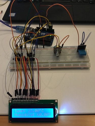
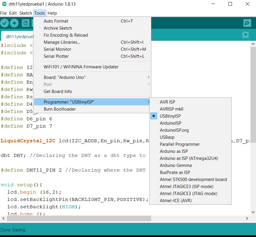
I used Arduino IDE to upload the code to my board using the USBtinyISP. First is necesarry to make the connections, (MOSI, MISO, SCK, RST, VCC, GND) from the programmer to the board,
then I connected the temperature and humidity sensor DTH11 and an LCD screen to show the data collected.
In Arduino IDE, make sure you select: Tools> Programmer >USBtinyISP. Then in Sketch > Upload using programmer.
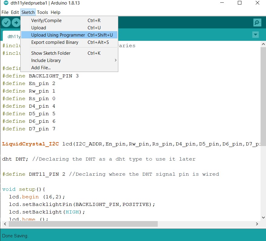
The following video shows the result:
Here you can Download the code I used.
And these very helpufull sites which help me to go though with the code:
Important:*In a previous exercise, I misconnected the sensor to my board, which caused it to no longer receive data correctly, this is why it shows these values.
I changed the sensor and now it shows true values, as shown bellow.
arduino files used this week
- All files for Arduino IDE used during this week are avaliable Here
Some thoughts about this assignment
There are so many chances that this exercise won't work that it's hard to stay positive all the time. On the other hand,
it is still a process that takes me a long time to understand which makes it even more frustrating. At first I thought that
taking a bigger risk would be an advantage to save a little time (according to what I had reviewed in previous student assignments)
but it turned out the opposite. These weeks of inputs and outputs seem to be endless and my board kept not working.
On the other hand, What I take from this week is that it is better to go step by step with smaller goals which will allow me
understand those basic concepts and practices, do not delay my progress on every week, and do not lose sight of the
key objective which is my final project.