OUTPUT DEVICES
An output device is any peripheral that receives data from a computer, usually for display, projection, or physical reproduction.
An output device is any peripheral that receives data from a computer, usually for display, projection, or physical reproduction.
Group assignment
- Measure the power consumption of an output device
- Document your work (in a group or individually)
Individual assignment
- Add an output device to a microcontroller board you've designed and program it to do something
Find out the details of our common work al ZOI Here.
In order to progressively understand the development of the code, the connections and other steps for this subject, I started doing some tests with Arduino.
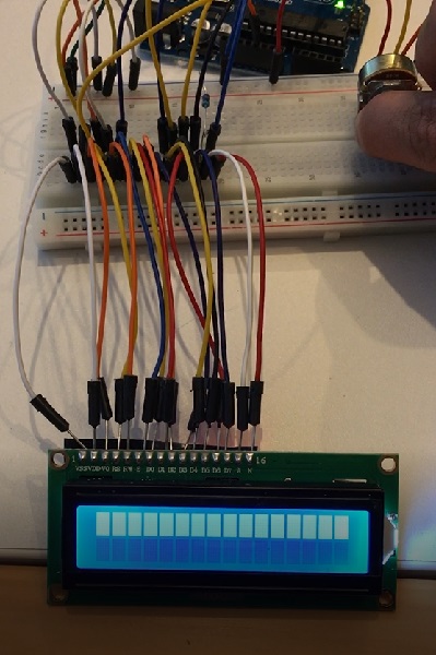
I started with some practice on the Arduino. The LCD I used is a 16×2 which means that the LCD has 2 lines, and can display 16 characters per line. Therefore, a 16×2 LCD screen can
display up to 32 characters at once. It is possible to display more than 32 characters with scrolling.
The data sheet of this component can be found in the next link:
LCD 16x2 data sheet
*Also, the pictures and further information was taken from Circuit basics
The pinout used for this is:
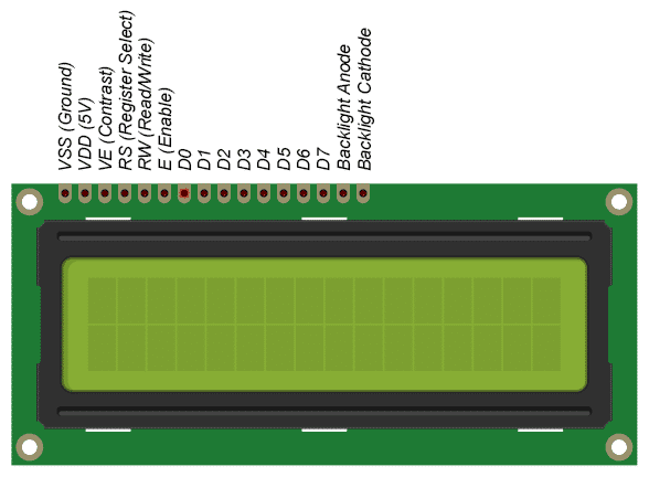
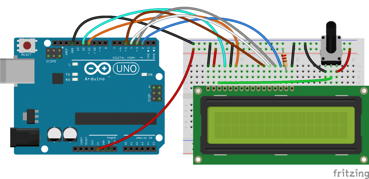
The connections needed for the arduino are:
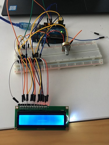
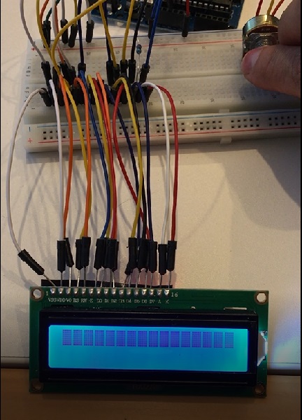
I had no headers to try this at home so I decided to solder the lcd pins, it looks messy and took a time to do it by finally I managed to se
the data on the screen which was what I was looking for.
The resistor used sets the backlight brightness. A typical value is 220 Ohms, but other values will work too.
Smaller resistors will make the backlight brighter. The potentiometer is used to adjust the screen contrast.
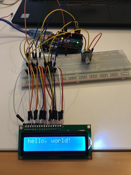
Then the fun part, send text to the screen, for this I used the following code to try.
#include

LiquidCrystal lcd(12, 11, 5, 4, 3, 2);

void setup() {
lcd.begin(16, 2);
lcd.print("hello, world!");
}

void loop() {
}
What you can see on the screen:
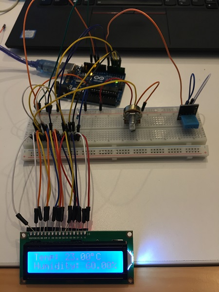
The code to show the results of the humidity and temperature sensor:
#include
#include

LiquidCrystal lcd(12, 11, 5, 4, 3, 2);

dht DHT;

#define DHT11_PIN 7

void setup(){
lcd.begin(16, 2);
}

void loop(){
int chk = DHT.read11(DHT11_PIN);
lcd.setCursor(0,0);
lcd.print("Temp: ");
lcd.print(DHT.temperature);
lcd.print((char)223);
lcd.print("C");
lcd.setCursor(0,1);
lcd.print("Humidity: ");
lcd.print(DHT.humidity);
lcd.print("%");
delay(1000);
}
You can see the results on the next video:
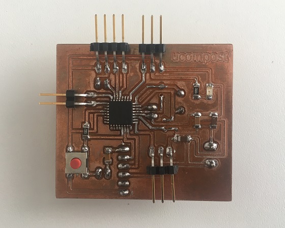
Decided to try my inputs board with output components. More details about this board can be found on my
week 10 site.
Connect the pins from the sensor to the board, remember to be aware that the pins of the Arduino are different than the ones on the micro.
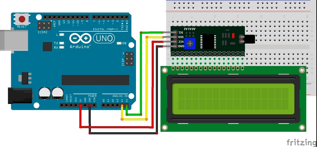
*This image was taken from Geek factory
First have to download and install the LCD I2C library avaliable on the next link:
Liquid Crystal I2C
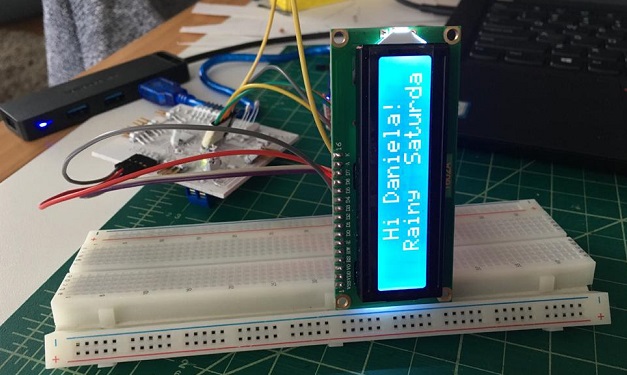
I used the code from the following site, and this is the result after a few modifications:
Hello World from John Rickman
//YWROBOT
//Compatible with the Arduino IDE 1.0
//Library version:1.1
#include

LiquidCrystal_I2C lcd(0x27,A4,A5);  // set the LCD address to 0x27 for a 16 chars and 2 line display

void setup()
{
    lcd.init();                      // initialize the lcd
    // Print a message to the LCD.
    lcd.backlight();
    lcd.setCursor(3,0);
    lcd.print("Hi Daniela!");
    lcd.setCursor(2,1);
    lcd.print("Rainy  Saturday!");
    lcd.setCursor(0,2);
    lcd.print("saturday");
    lcd.setCursor(2,3);
    lcd.print("Daniela");
}


void loop()
{
}
To start make sure about the module pinout, I found this picture to show this, because the wrong connections could cause
color confusions in te result :
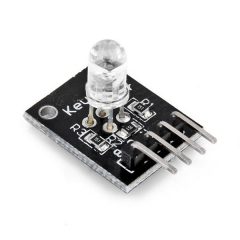
Connect the pins to the board:
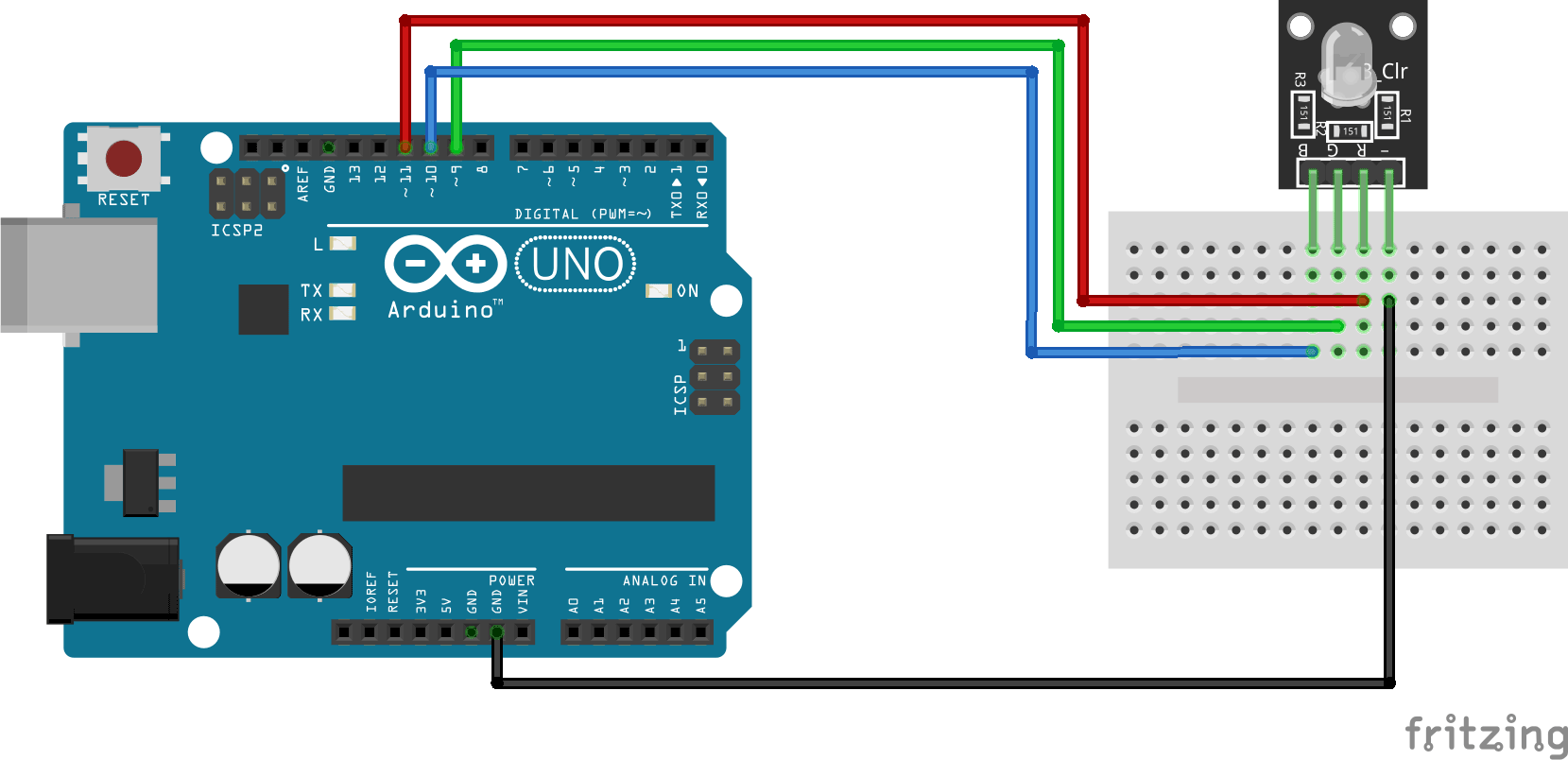
/*
Adafruit Arduino - Lesson 3. RGB LED
*/

int redPin = 11;
int greenPin = 10;
int bluePin = 9;

//uncomment this line if using a Common Anode LED
//#define COMMON_ANODE

void setup()
{
    pinMode(redPin, OUTPUT);
    pinMode(greenPin, OUTPUT);
    pinMode(bluePin, OUTPUT);
}

void loop()
{
    setColor(255, 0, 0);  // red
    delay(1000);
    setColor(0, 255, 0);  // green
    delay(1000);
    setColor(0, 0, 255);  // blue
    delay(1000);
    setColor(255, 255, 0);  // yellow
    delay(1000);
    setColor(80, 0, 80);  // purple
    delay(1000);
    setColor(0, 255, 255);  // aqua
    delay(1000);
}

void setColor(int red, int green, int blue)
{
    #ifdef COMMON_ANODE
    red = 255 - red;
    green = 255 - green;
    blue = 255 - blue;
    #endif
    analogWrite(redPin, red);
    analogWrite(greenPin, green);
    analogWrite(bluePin, blue);
}
You can find a lot of examples to work with, here is another one I tryed and found interesting.
RGB Leds Arduino
/*

THREE COLOUR (FULL COLOUR) LED

Revised: 20th October 2018
By Seb Jensen

RED GOES TO D11
GREEN GOES TO D9
BLUE GOES TO D10
GROUND GOES TO GROUND

*/

int redpin = 11; //select the pin for the red LED
int bluepin =10; // select the pin for the  blue LED
int greenpin =9;// select the pin for the green LED

int val;

void setup() {
    pinMode(redpin, OUTPUT);
    pinMode(bluepin, OUTPUT);
    pinMode(greenpin, OUTPUT);
    Serial.begin(9600);
}

void loop()
{
for(val=255; val>0; val--)
    {
    analogWrite(11, 255);
    analogWrite(10, 0-val);
    analogWrite(9, 0-val);
    delay(1);
    }
for(val=0; val<255; val++)
    {
    analogWrite(11, 255);
    analogWrite(10, 0-val);
    analogWrite(9, 0-val);
    delay(1);
    }
    Serial.println(val, DEC);
}
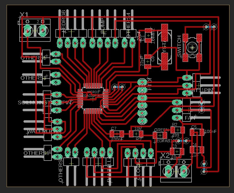
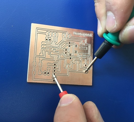
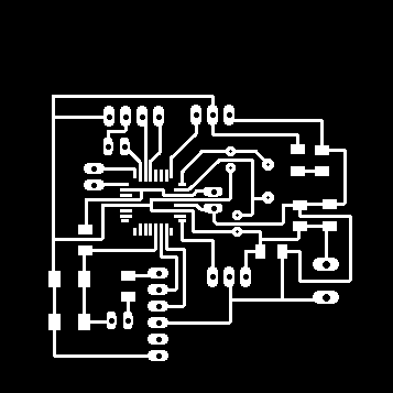
Based on the inputs week, I simplified the design and planned it work with the following components:
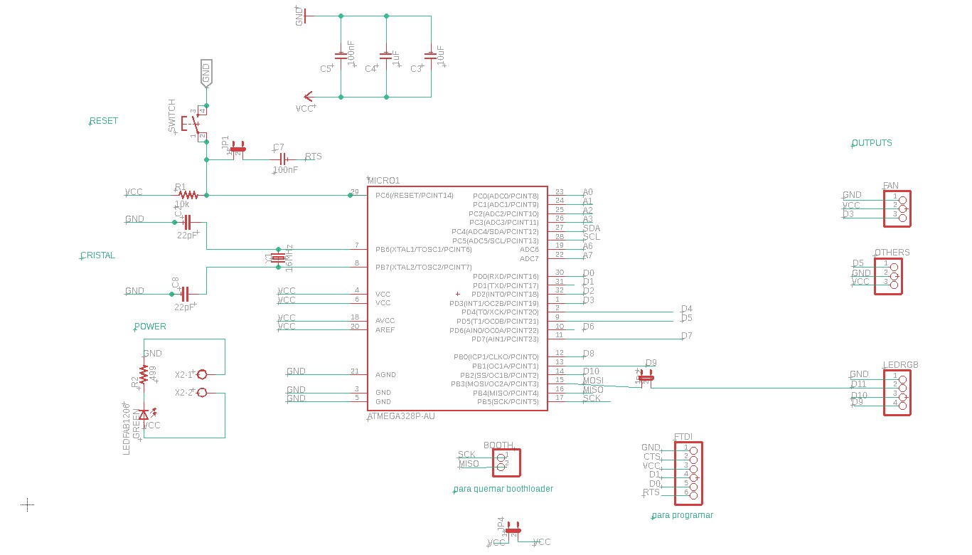
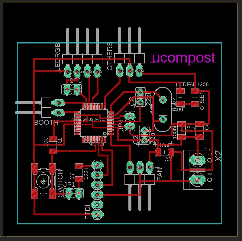
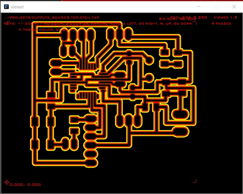
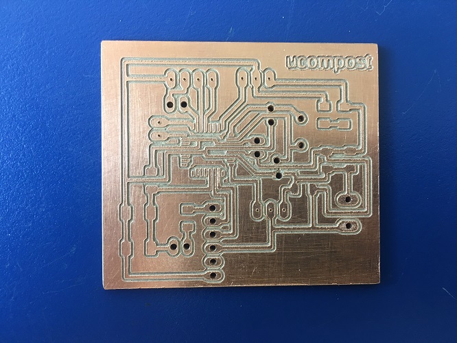
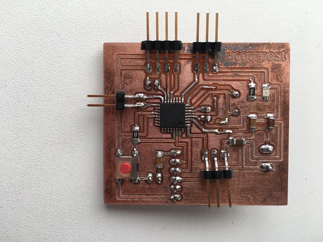
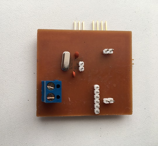
Some pictures of the milling process:
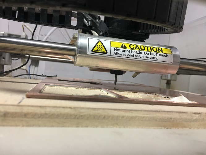
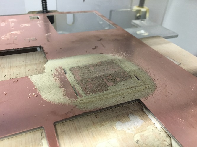
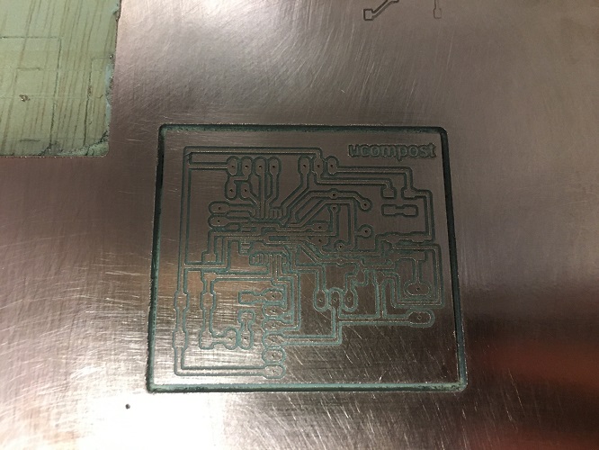
Used a dremel to make the holes, checked the contiunity, and welded the components.
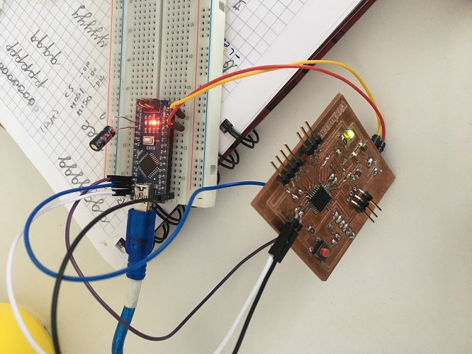
The first step is to burn the bootloader. Details about this process can be found on my
Input devices week but here I leave some pictures of the process:
The first test was with the rgb led, this was the code I used:
/*
Adafruit Arduino - Lesson 3. RGB LED
*/

int redPin = 11;
int greenPin = 10;
int bluePin = 9;

//uncomment this line if using a Common Anode LED
//#define COMMON_ANODE

void setup()
{
    pinMode(redPin, OUTPUT);
    pinMode(greenPin, OUTPUT);
    pinMode(bluePin, OUTPUT);
}

void loop()
{
    setColor(255, 0, 0);  // red
    delay(1000);
    setColor(0, 255, 0);  // green
    delay(1000);
    setColor(0, 0, 255);  // blue
    delay(1000);
    setColor(255, 255, 0);  // yellow
    delay(1000);
    setColor(80, 0, 80);  // purple
    delay(1000);
    setColor(0, 255, 255);  // aqua
    delay(1000);
}

void setColor(int red, int green, int blue)
{
    #ifdef COMMON_ANODE
    red = 255 - red;
    green = 255 - green;
    blue = 255 - blue;
    #endif
    analogWrite(redPin, red);
    analogWrite(greenPin, green);
    analogWrite(bluePin, blue);
}
This video shows the result:
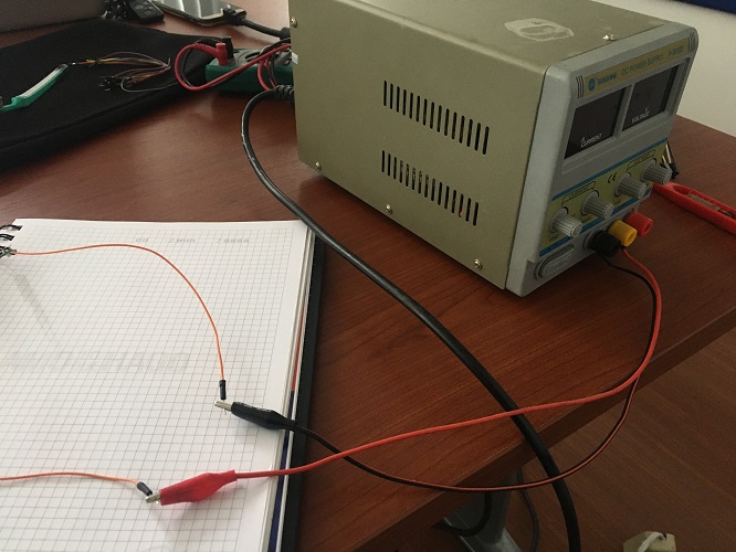
Next thing we tryed is to connect the fan, to do this it was necessary and external power supply and a relay, the following picture shows the connections we made (Diego helped my throughout this process).
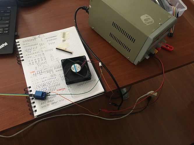
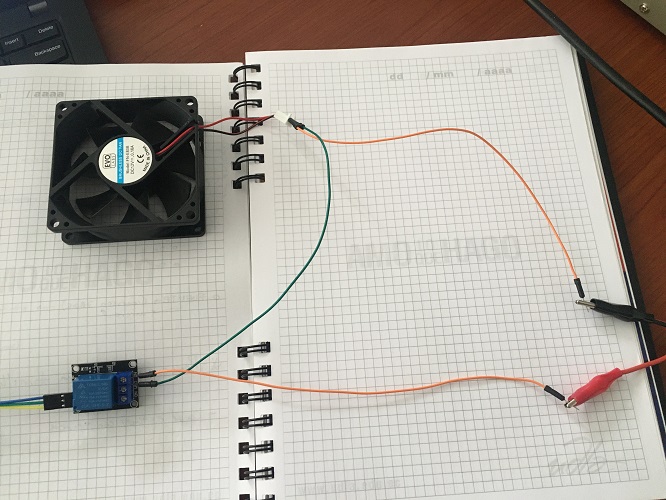
We used an external relay, this video shows the result:
This is the code we used:
// constants won't change
const int RELAY_PIN = 3;  // the Arduino pin, which connects to the IN pin of relay

// the setup function runs once when you press reset or power the board
void setup() {
    // initialize digital pin A5 as an output.
    pinMode(RELAY_PIN, OUTPUT);
}

// the loop function runs over and over again forever
void loop() {
    digitalWrite(RELAY_PIN, HIGH); // turn on fan 5 seconds
    delay(5000);
    digitalWrite(RELAY_PIN, LOW);  // turn off fan 5 seconds
    delay(5000);
}
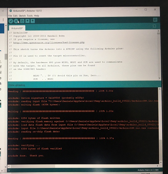
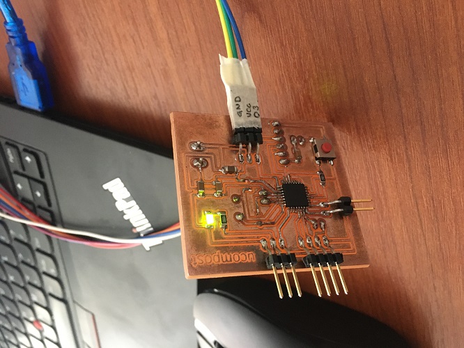
For this board I tryed connecting an rgb leb and programmed it using the USBtinyISP. First make all the connections from the programmer to the board, then
connected the led and uploaded the code using Arduino IDE.
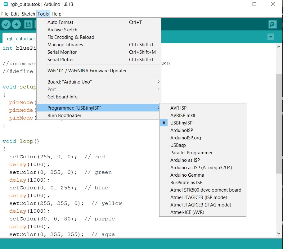
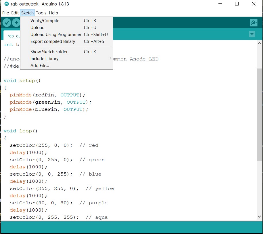
In Arduino IDE remember: Tools> Programmer >USBtinyISP. Then in Sketch > Upload using programmer.
At first try something was not working, I received this message that indicates to double check the connections. So I realized that it was better to connect MISO directly from the first pin (removing the bridges on the back),
and same for the reset, as shown bellow.
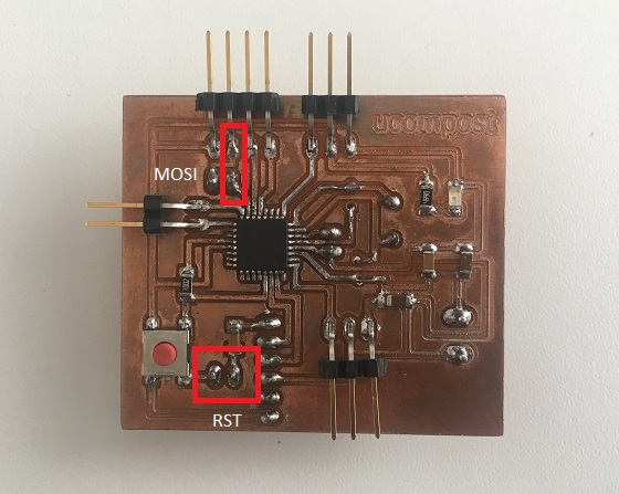
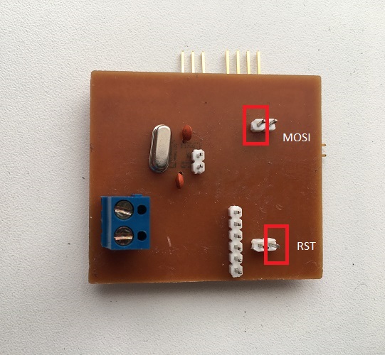
Another important thing to notice is that the RGB led used for red the same pin used as MOSI, so I first made to connections just to upload the code and then connected the led.
Tryed again to upload the code and this is the result:
Here you can Download the code I used.
And I encourage you to visit this very helpufull sites which help me to go though with the code:
I also tried sending some text to an LCD, with my board from inputs week, same process in the Arduino IDE, and this is the result:
Here you can Download the code I used.
This site was very helpufull to go though with the code:
surtr technologysimple use write from serial monitor.
By having a new microcontroller (in the case of my board, the ATMega 328), it comes "factory clean", that is, it does not have any program loaded, for this reason it is necessary to burn the Bootloader,
which is a boot manager so that the different sketches can be programmed using the Arduino software (Arduino IDE)
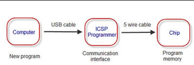
ICSP programming is the ability of some devices to be programmed while installed in a complete system rather than requiring a chip that has been pre-programmed
before being installed in the system. Generally the chips that support ISP allow to generate the programming from the conventional power line and communicate
through a serial protocol , which means that data is sent in series.
ICSP is a direct programming method for the microcontrollers of AVR, PIC and others. As they are soldered to the board, is necessary an ICSP connector and
and a programmer to program them, that's when our USBtinyISP comes into the picture.
To upload any sketch it is necesarry to be aware of the pins required, in the case of the ATMega328P used in my boards, this is the detail:
The pins required in the case of the ATMega328P are the following:
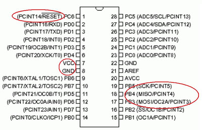
* This information and images were taken from:
Aprendiendo Arduino, ICSP.
Circuit digest, serial communication protocols.
This is still very challenging for me, I still have to try other sensors and keep working on my final project.
So far, Im trying to imporve my understanding on programming and coding, but is still a long road to go.
Diego has been really helpfull with this assignment and has guided me through this process.
At this point I can understand the code that others have created but it is still very difficult for me to generate a new one.