Week 10. Input Devices
Group assignment
- Probe an input device's analog levels and digital signals
Individual assignments
- measure something: add a sensor to a microcontroller board that you have designed and read it
Have you
- linked to the group assignment page ✓
- Documented what you learned from interfacing an input device(s) to microcontroller and how the physical property relates to the measured results✓
- Documented your design and fabrication process or linked to previous examples.✓
- Explained the programming process/es you used ✓
- Explained problems and how you fixed them✓
- Included original design files and source code ✓
- Included a ‘hero shot/video’ of your board ✓
Group Assignment
Here is the link to the group assigment page.
Input devices with ATtiny45
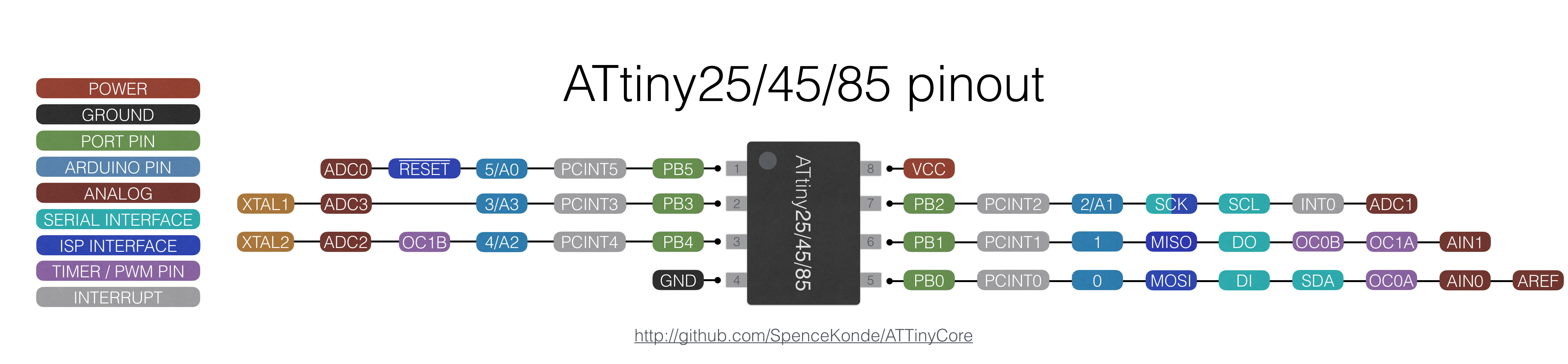
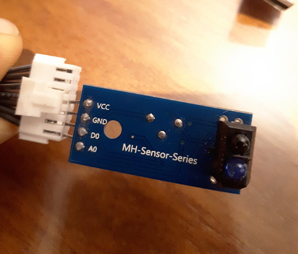
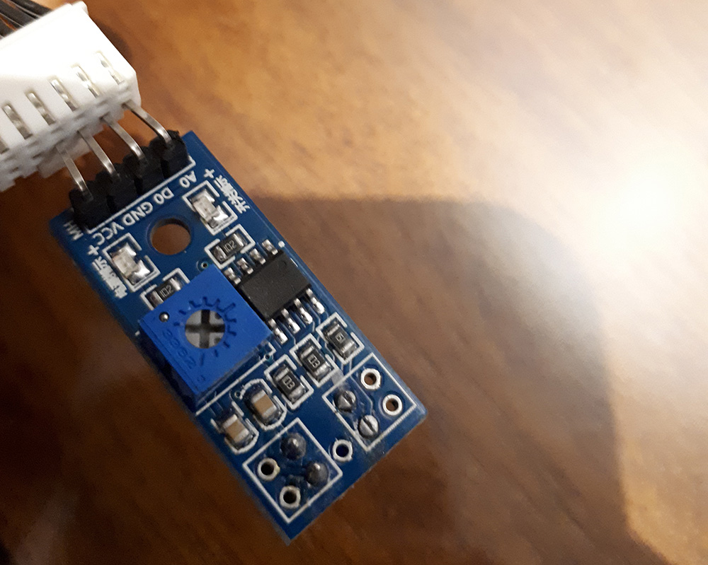
This week I decide to use the Attiny45 for this assignment because it's enough to read an analog input, a digital input, Serial communication using SoftwareSerial Library and even with that have an analog pin free to use. All of this with internal clock. I find in my old electronics things an old TCRT5000 Module which have an IR emitter and a phototransistor incorporated and can be use for some applications as detect white and black color (commonly used in line follower robot) distance detection (short distances), position sensor for shaft encoder and more. This module have an analog output and digital output so it's perfect to test and read from the same sensor both kind of signals.
Design
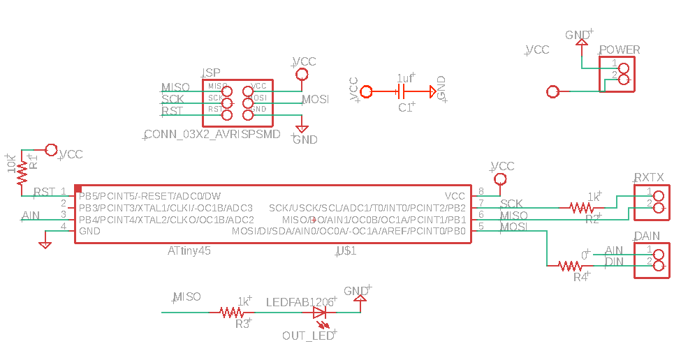
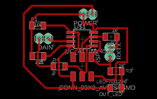
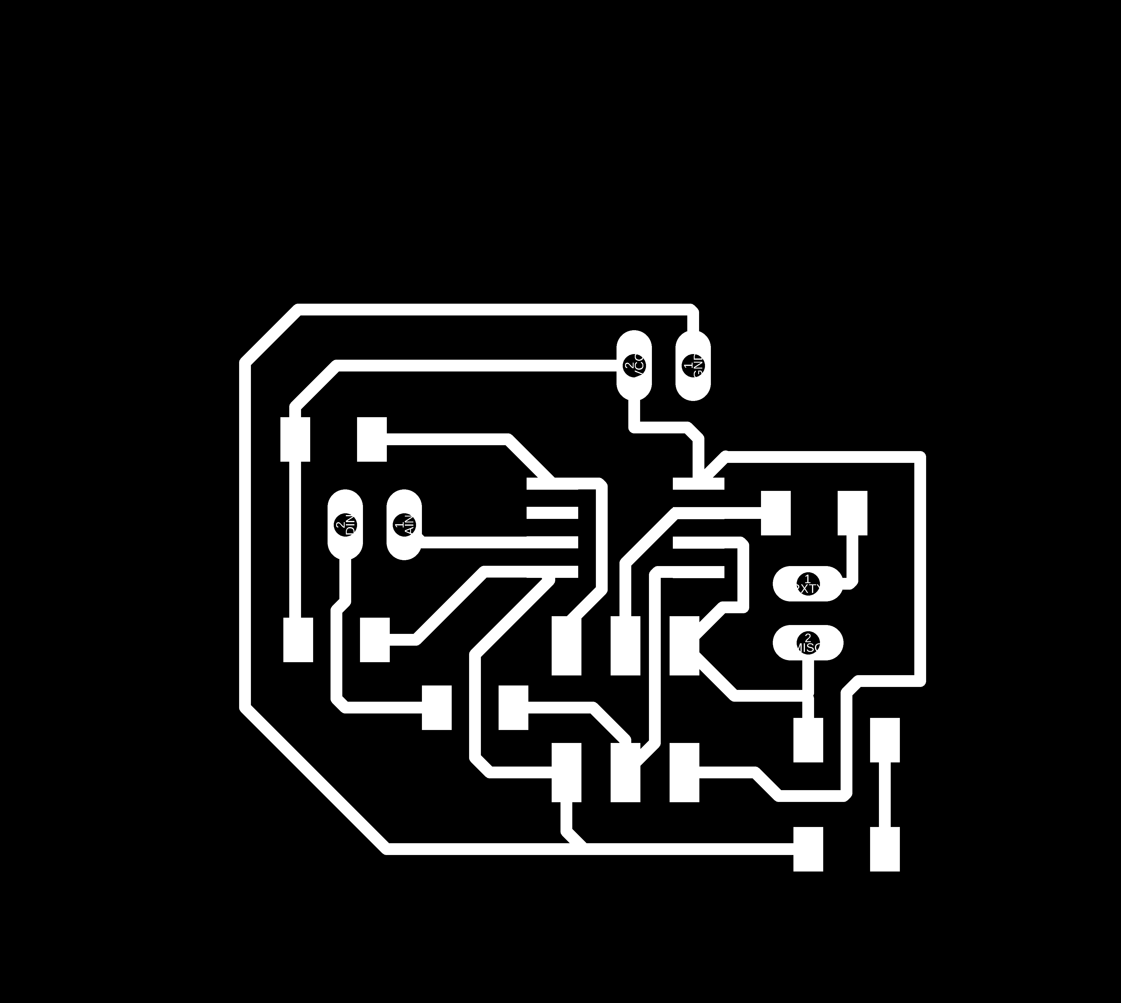
I was thinking to use an ATtiny44 because the number of pins but I review the ATtiny45 pinout and check if will be enough to serial communication. After some planning on the pins I realize it's enough and the pcb will be smaller which is the intention of using smd components. I decide to put the ISP pin header and others pair of male pins to connect Rx,Tx ; Ain, Din and Vcc, Gnd with this pin ditribution, routing was easier than FTDI header that I try to use first. I put a LED on MISO which is also connect to Tx male pin the reason of this is to have a visual indicator while the micro is being programmed and the same when is sending/reciving information using Serial protocol.
BOM
| Part | Value | Device | Package | Description | POPULARITY |
| C1 | 1uf | CAP_UNPOLARIZEDFAB | C1206FAB | ||
| DAIN | PINHD-1X2 | 1X02 | PIN HEADER | 98 | |
| ISP | CONN_03X2_AVRISPSMD | CONN_03X2_AVRISPSMD | 2X03SMD | ||
| OUT_LED | LEDFAB1206 | LEDFAB1206 | LED1206FAB | LED | |
| POWER | PINHD-1X2 | 1X02 | PIN HEADER | 98 | |
| R1 | 10k | R1206FAB | R1206FAB | Resistor (US Symbol) | |
| R2 | 1k | R1206FAB | R1206FAB | Resistor (US Symbol) | |
| R3 | 1k | R1206FAB | R1206FAB | Resistor (US Symbol) | |
| R4 | 0 | R1206FAB | R1206FAB | Resistor (US Symbol) | |
| RXTX | PINHD-1X2 | 1X02 | PIN HEADER | 98 | |
| U$1 | UC_ATTINY45SI | UC_ATTINY45SI | SOIC8 |
Milling
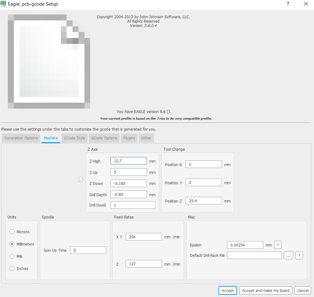
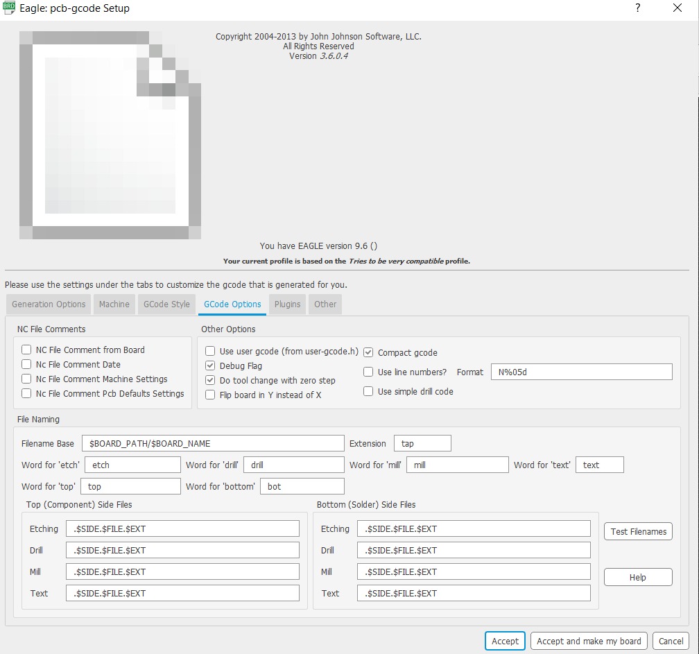
With the other PCBs I've always used MODS to generate the G-Code so this time I wanted to do it direct from EAGLE with the plugin, to do that, I first had to download it HERE. I use this tutorial as a guide in the installing process from Jakob Nilsson's Fab Academy page and then to choose the right settings for the machine in ZOI Diego made the following screen shots.
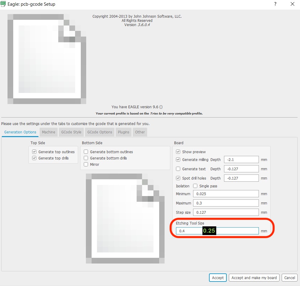
The only parameter I change was the "Etching tool size" according to the milling bit I will use from 0.4 to 0.25 as you can see in the image above.
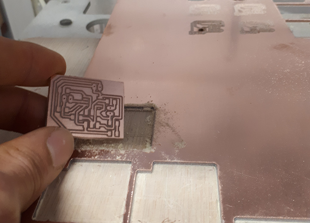
Results
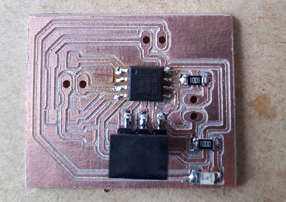
Everything fine with traces width, milling depth and the surface finish.
Soldering
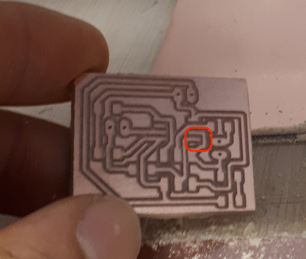
I first place the ATtiny45 but I had to remove it beacause there was a trace really close to a pin and were in shortcut in the place is marked in the picture.
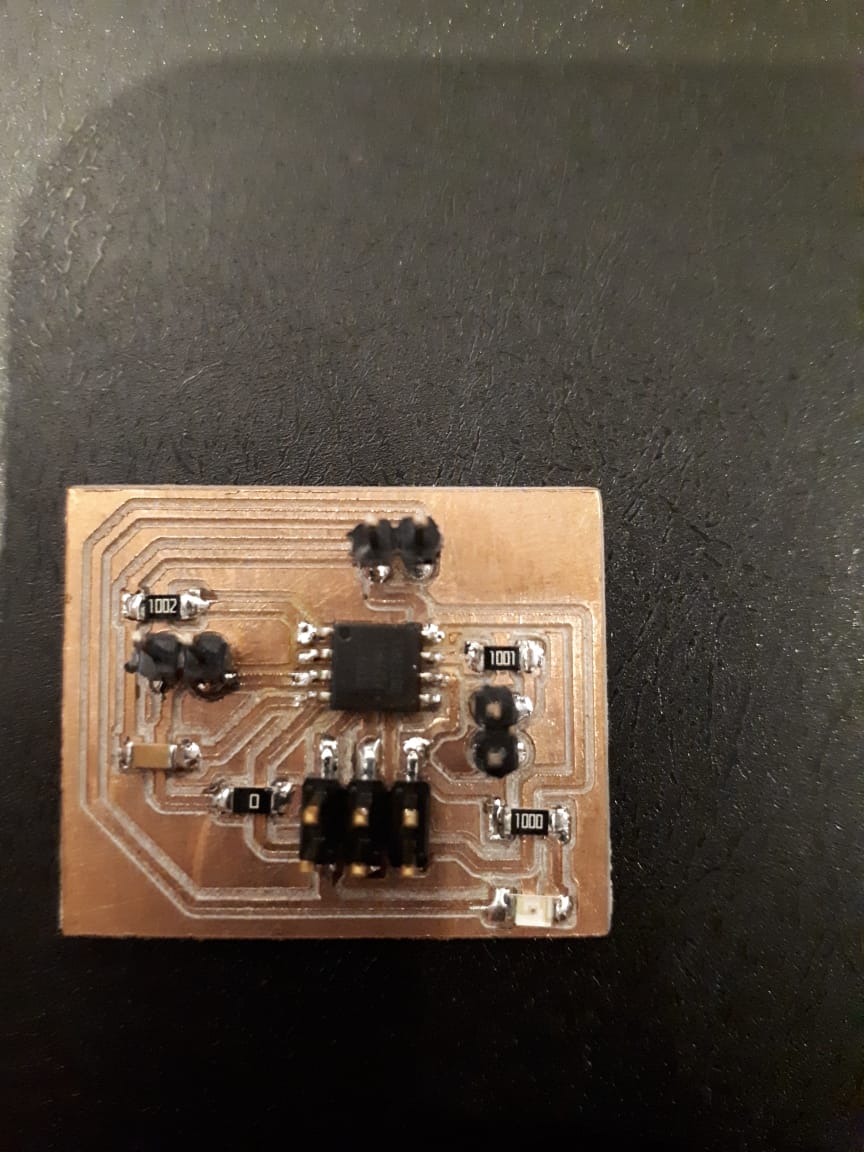
After this I continue soldering until finished.
Programming
My FabTinyISP it's not working well so I have to use an Arduino to program this analog/digital inputs board, then I use the same Arduino as serial bridge to read the values of the sensor in serial port.
Here is the uploading process.
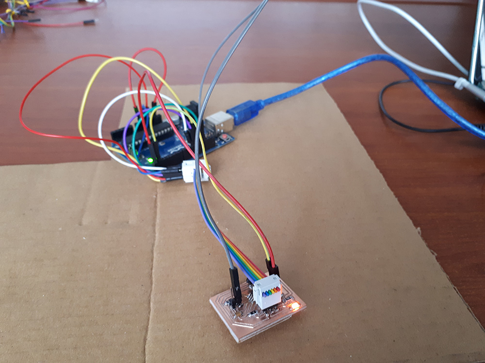
Now connecting the module pins, vcc, gnd and digital, analog signals to the board and the Tx, Rx pins from the board to Arduino, everything was ready to read the values. This module have a potenciometer to calibrate the sensitivity of the digital signal to change from one to zero. This can be usefull if you don't need to map the analog values, in other words, show data to the user to be read as distance. It's also important to notice using analog signal will be always more precise than a potenciometer calibration in this module and could be cases is needed to detect different positions of an object and not just care obout a "border line" in this cases will be convinient read an analog signal.
Here is a video to see how both values digital and analog change when an object interrupt the infrarred light. An interesting thing is that our eyes can't see the infrarred spectrum but cameras can do and make visible for humans. This is a way to know if an IR emitter is power on, working or not.
Some thoughts About this week
It is very important to understand the difference from analog and digital. That knowledge allows to process different signals, for example audio or an analog sensor reading. About digital signals, understand that can simmulate an analog one, for example PWM but will never be the same or equivalent. How a DAC works to know when converting a signal there is a lot of information lose.