Although I’ve been playing with input devices in previous weeks this will be the first week in which I’ll be creating my own board (with an input sensor) from total scratch! No schematic to start with, and completely free to try out any kind of input device, although it would be smart to focus on what I’d need for my final project; exciting and somewhat scary at the same time.
Assignments
Our tasks for this week are:
- Group assignment: Probe an input device’s analog levels and digital signals
- Individual assignment: Measure something: add a sensor to a microcontroller board that you have designed and read it
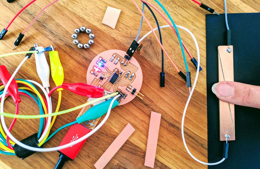
Hero Shots
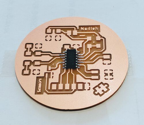
Showing some final results from my circular board, that had a sensor for magnetism, touch and simple (external) switches, for the tl;dr and hopefully showing you why the rest of this very long blog could be interesting to read (⌐■_■)
Playing with Input Devices
At the start of this week I learned that there are many different kinds of input devices. During Neil’s lecture and Henk’s presentation in the lab the next day I saw many interesting techniques come by.
During the afternoon in the lab we got to play with several of these in groups. Let me walk you through some of the types of things input devices can sense, weaving it together with those I played with in at the Waag.
I started the group assignment by explaining how to use a logic analyzer to Loes, Lucia and Nicole. We’d all seen Henk use it during the Electronics Design week, but I’d been the only one of our group of 8 that had actually used it. I’m definitely not saying I was an expert, far from it, I was barely beyond a complete beginner. But at least I knew just enough to show the other three ladies how to see the HIGH/LOW states coming in on the Saleae Logic2 app.
For ease, I first hooked up my logic analyzer to my hexagonal board, using one wire for GND and another channel to measure some input. My board was still programmed to blink the LED with a frequency based on the value that the phototransistor was measuring. I attached it to the pin that was sending out from the ATtiny412 to the LED and we could see how fast the HIGH/LOW state changed by how much I was covering/lighting the phototransistor.
I was curious to see what the logic analyzer would return when I connected a channel to the phototransistor, since it’s sending an analog signal, and the logic analyzer is meant for digital ones (only 0 and 1). As sort-of expected I got only two results; a fully low state when I shined a flashlight onto the phototransistor, and a high state in the general brightness of the room.

Switch
A switch is one of the most basic input devices, going from a one level to another when the switch is activated.
During last week’s “Mechanical & Machine Design” I used and programmed for an end stop in our folding lamp, which is basically a switch.
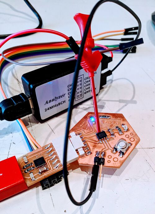
I connected a channel from the logic analyzer to the pin going to the button on my hexagonal board and saw that the HIGH/LOW state changed exactly as I pressed the button, with LOW occurring when I pressed the button (since I had set it up to be an INPUT_PULLUP using the internal resistor of the ATtiny412’s pin):

We also did the same for Loes' own board, where we saw a slightly different result; many bounces before the button’s signal would settle. This was because Loes' button wasn’t set to INPUT_PULLUP, and thus we were seeing the chaotic behavior during presses.

Having measured all the input devices on my hexagonal board with the logic analyzer, I figured it was time to bring out the breadboard and try to measure some other sensors. I started with recreating a button following this Arduino example.
I then added a wire from the logic analyzer’s GND to the GND in the breadboard, and another wire from channel 0 to the same row that was capturing the button’s state in the Arduino.
As expected, the button on the breadboard showed the same up-down behavior in the logic analyzer that I’d seen with the button on my own board.
Motion
During the lunch break, Loes, Lucia and I had gone through the electronics drawers in the lab to try and find some interesting looking sensors that could be used with wires/breadboards. I’d grabbed a few things, and the first I wanted to try was the dome-like PIR (Passive InfraRed) motion sensor (although Neil had mentioned that this was outdated, and we should use a Doppler radar sensor instead).
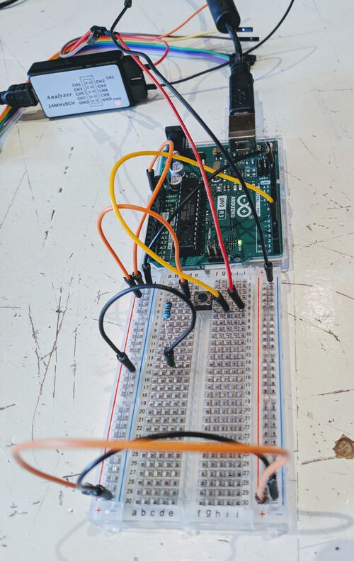
I looked up a tutorial on how to connect the PIR to an Arduino. However, there were only 3 connection points to the PIR; 5V, GND and the Out pin for the sensor value, so I skipped the breadboard and just connected the PIR straight to the Arduino with wires.

I adjusted an example to be even more simple, and output in Serial if it saw motion or no motion:
//Measure the PIR motion detection
#define pin_PIR = 8
int value;

void setup() {
  Serial.begin(9600);
}//void setup

void loop() {
  value = digitalRead(pin_PIR); //read state of the PIR

  if (value == LOW) {
    Serial.println("No motion");
  } else {
    Serial.println("Motion!");
  }//else

  delay(1000); //a delay of 100 would've been better I think
}//void loop
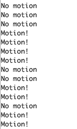
And as we waived in front of the PIR (or not) we could see the Serial statements come by in the Serial monitor.
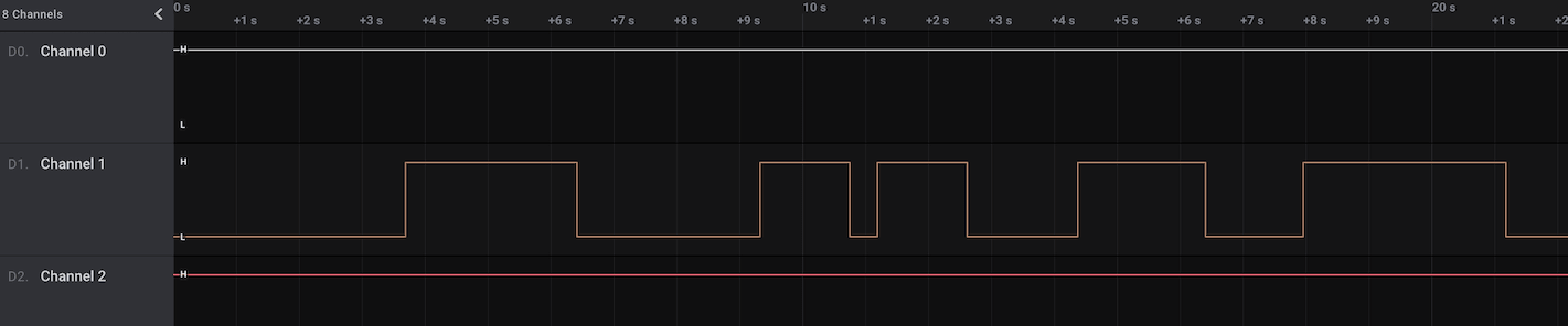
Loes and I connected the logic analyzer to the wires running between the PIR and the Arduino, and could measure when it registered motion or no motion.
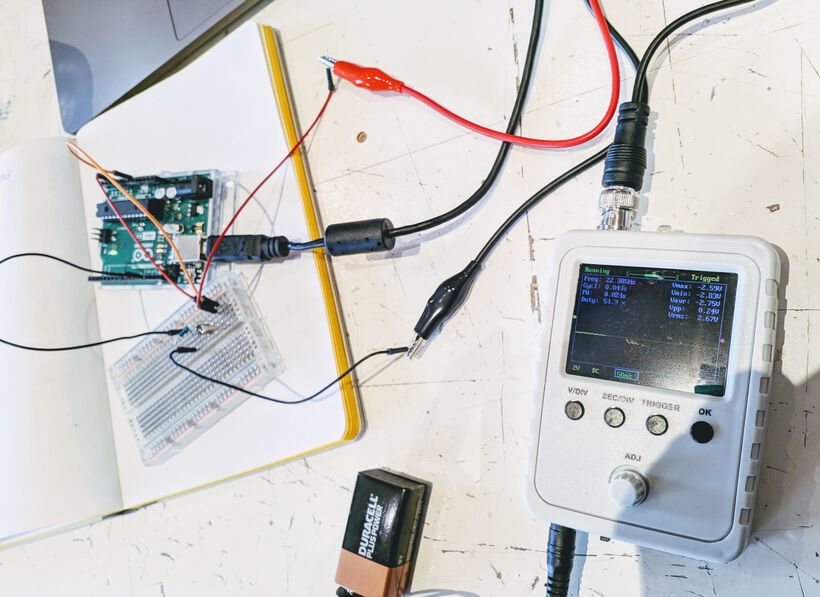
Lucia had brought her tiny oscilloscope along, which I really wanted to try, because we never got to play with this ourselves yet (only having seen Henk operate one). After figuring out that this was a JYE DSO150 oscilloscope, I looked up a video and accompanying tutorial to try and learn how to use it.
Thankfully it didn’t have too many buttons. There is a slider button at the top that can be set to AC, DC and GND, which I set to DC. The oscilloscope had two alligator clips coming out the top, but at first I didn’t connect the black wire, because both Loes and I remembered that Henk was only using one wire during his demonstration a few weeks ago. However, after seeing the demo online, we saw that the black wire was indeed supposed to be connected to GND.
To get a sense of how the voltage and time settings worked, I clipped the red wire to the test signal “thingy” at the middle top of the oscillator, and then adjusted the settings until I saw a digital signal on the screen:

By pressing the V/DIV button you can adjust the scale of the voltage / y-axis by rotating the little dial. And by pressing the SEC/DIV button, you can adjust the scale of the time / x-axis by rotating the little dial. Those were all the things I used on the oscilloscope.
However, when Loes and I connected the oscilloscope to the wires running between the PIR and the Arduino at first we weren’t able to get a sensible signal from the oscilloscope. But eventually we managed to get the settings for the x and y axis in a combination where the HIGH and LOW signal from the PIR was showing up (I believe it was 2V and 0.Xs).
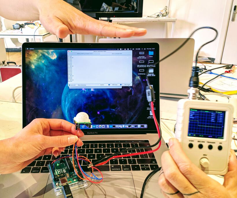
When we had something working, Lucia and Nicole came to watch, and together we managed to create a video that showed both the Serial output on my laptop and the result on the oscilloscope while Lucia was moving her hand in and out:
It was clear from the oscilloscope that the PIR was giving off a binary result, either low or high.
Light
To measure the light level, generally a phototransistor, or -resistor is used. I’ve already played with the phototransistor on my personal board during the “Embedded Programming” week. But also with an LDR (Light Dependent Resistor) during the “Machine & Mechanical Design” week to make our lamp open and close based on the amount of light in the room.
We found a funky looking phototransistor (a 3DU5C) that looked like and LED and could be used on the breadboard. I figured this should give off an analog signal, and would thus be interesting to measure with the oscilloscope.
I looked up how to connect a phototransistor to an Arduino, and the tutorial showed it was the same as how we’d hooked up the LDR to our lamp from last week, with a “T-junction” going on with a 10K resistor and the sensor running towards the analog pin.
I copied the simple program from the tutorial to be able to read off the value returned by the sensor:
//Measure the phototransistor
#define pin_Photo A0
int value;

void setup() {
  Serial.begin(9600);
}//void setup

void loop() {
  value = analogRead(pin_Photo);
  Serial.println(value);
  delay(10); // wait 10ms for next reading
}//void loop
It was again quite some fiddling with the oscilloscope to be able to see some useful signal coming from the light sensor. But we eventually got something by using 2V and 50ms.
The results of covering up the sensor weren’t quite seen as big changes by the sensor. Lucia therefore grabbed one of the magnifying lamps from a soldering station (which have a very bright light). Moving this lamp over and away from the light sensor was clearly visible on the oscilloscope, also with it having a gradual in- and decrease from high to low (showing that it was indeed an analog signal):
Distance
You can measure distance using sonar, using ultrasonic waves which are transmitted by one side and received by the other side. As an example, Henk showed us the results of measuring this sonar device with a logic analyzer.

The sonar module uses a trigger pin that gets a ping for a few microseconds from the Arduino. Then the transmitter sends our 8 pings of ultrasonic sound. Next, the echo pin will be set to HIGH until the receiver receives back the first sonar echo, after which the echo pin is back to LOW. The distance is then the time it took between the first ping transmitted and the first echo received, divided by two (the distance is travelled twice) and divided by the speed of sound.
Henk showed these steps on the results of the logic analyzer, but was missing the transmitter sending out 8 short pings, because that pin apparently didn’t have a way to connect to the logic analyzer (something had to be soldered first). But we could indeed see that first ping from the Arduino, then the echo being set to high, and the final channel receiving back way more than 8 echos, due to the sounds bouncing off the room multiple times.
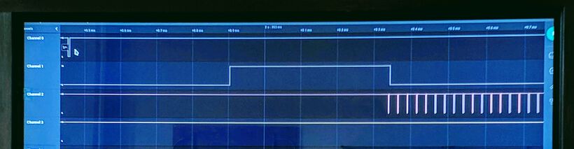
Seeing exactly how the sensor worked by watching the results of the logic analyzer was quite cool!
Light Radar
There is now a better way that uses a “light radar” to measure distance even more accurately than sonar (and in a much smaller package). This component is also apparently at the edge of what humans can solder on a board, and thus often a module is used to attach it to your board.
I was actually quite fascinated by this when seeing Neil’s lecture, and thus really wanted to test it. I asked Henk if we had a board with the light radar, and he gave me one, as long as we promised to be very careful with it (it’s expensive).
I just want to point out what the subtitle of this wonderful light radar packaging is: “An all-singing all-dancing time-of-flight distance sensor that uses PEW PEW LASERS!" (^ᗨ^) Add in some sharks and it would’ve been perfect!

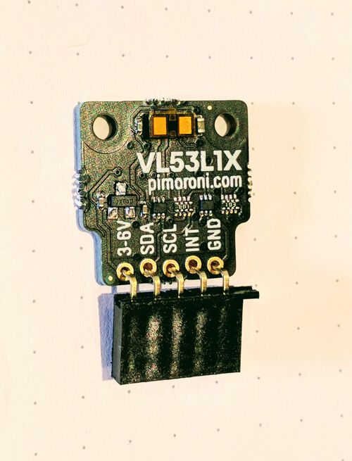
While searching for the VL53L1X and Arduino, I found that there are several libraries, yay! I decided to install this one by Polulu: In the Arduino IDE go to Sketch -> Include Library -> Manage Libraries, next search for VL53L1X and install the one made by Polulu.
I opened the VL53L1X example that came with the library, found under File -> Examples -> VL53L1X -> Continuous and used this as is, making no changes and uploading it to my Arduino:
//This example shows how to take simple range measurements
//[in mm] with the VL53L1X
#include <Wire.h>
#include <VL53L1X.h>

VL53L1X sensor;

void setup()
{
  Serial.begin(115200);
  Wire.begin();
  Wire.setClock(400000); // use 400 kHz I2C

  sensor.setTimeout(500);
  if (!sensor.init()) {
    Serial.println("Failed to detect and initialize sensor!");
    while (1);
  }//if

  sensor.setDistanceMode(VL53L1X::Long);
  sensor.setMeasurementTimingBudget(50000);
  sensor.startContinuous(50);
}//void setup

void loop() {
  Serial.print(sensor.read());
  if (sensor.timeoutOccurred()) { Serial.print(" TIMEOUT"); }
  Serial.println();
}//void loop
This board had 5 connections, and although Loes and I understood to connect the 3-6V to a 5V pin on the Arduino and the GND to GND, the SDA and SCL were new to us. Thankfully, looking up an Arduino Uno pinout image showed that the analog pins A4 and A5 were SDA and SCL respectively.
We weren’t sure what to do with the INT connection, and just left it out to see if this was already enough. To help make the connection between the non-soldered through-holes of the VL53L1X board and the wires to the Arduino, we used a breadboard. Nevertheless, it was still a little fiddly.
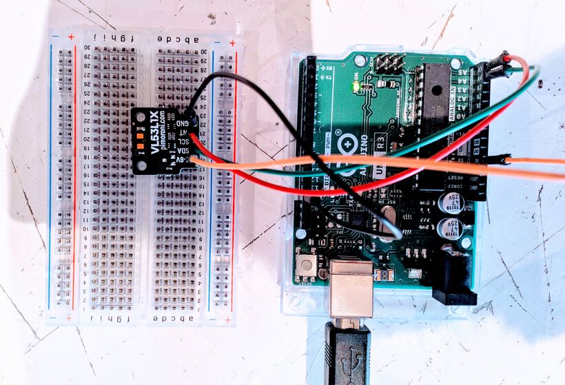
Lucia and Nicole came to watch again once Loes and I had the example code working. Together we tried to create a video to show how the measurements change in my Serial Monitor as Lucia is moving her hand slowly inward:
Magnetic Field
To measure the electric field, sensors use the Hall Effect. I decided to use a Hall Effect sensor on my own board, because magnets are just cool. I’ll therefore be getting into these measurements farther below in the “Magnetism” section.
Step Response
A step response sensor was Neil’s favorite. I think it was because you can measure so many different things with it, such as resistance, capacitance, inductance, position, pressure, force, tilt, acceleration, humidity, proximity, touch, multi-touch, bending, and more. But also because it’s as simple as using two copper sheets, which are separated from each other by some insulating material.
Because Neil had recommended that I’d look into the touch aspect to detect if a puzzle piece would be placed (during the random review a few weeks ago), I created two capacitive touch sensors on my own board, which you can read more about in the “Designing My Board” section below.
Temperature
There are a few different ways to measure temperature, although they are all generally based on the idea of resistance changing with temperature. There is RTD (Resistance Temperature Detector) where as the temperature goes down the resistance goes down as well. And there are NTC (negative temperature coefficient) thermistors, where as the temperature goes down the resistance goes up (hence the wording of negative coefficient).
For the RTDs the resistance versus temperature relationship is nearly linear for a wide range of temperatures. This makes RTDs more suitable for use in applications where measurements are made over a wide range of temperatures. NTCs on the other hand, have a non-linear relationship between resistance and temperature. This can be beneficial when accurate temperature measurements are needed within a relatively narrow range of temperatures (e.g. a window of ±50°C wide).
Neil also quickly showed the usage of a bridge configuration by using 3 normal resistors and an amplifier, which allows a more accurate reading of the temperature, and to minimize errors (see the board under temperature on this page):

Other
There are many other forces and inputs that can be captured with sensors. For example, Neil (quickly) discussed the following examples, which I didn’t play with at the lab (because there’s only so much time):
- Acceleration, orientation and rotation | With either a 3-axis accelerometer, or a 6-axis accelerometer+gyroscope. However, these are really at (or perhaps beyond) what a human can solder on a board.
- Location and time | You can get modules that use NEO-6M with which you can pick up GPS
- Sound | Neil mentioned during his lecture that electric microphones are obsolete and that we should use a digital MEMS instead. However, I believe he also said that these use I2S for communication which isn’t trivial, but that bigger processors have in-built ways to talk to I2S directly, such as the SAMD21.
- Force | Neil recommended to use a strain gauge and not a force sensing resistor, but he didn’t really go into this much further
- Vibration
- Pressure
- Heart beat and oxygen levels
- Air pollution
- Gases
The final input was Image recognition, a very interesting subject in and of itself. I didn’t truly get to try this, however, during the “Embedded Programming”” week I did play with the ESP32-CAM and got the camera to work with the default example (although the resulting image wasn’t calibrated well).
Designing My Board
For our individual assignment we have to design our own board from scratch. It has to have (at least) one sensor that we’ll have to program and be able to read the values it senses.
For this week I really wanted to explore ways that I could use for my final project; what sensors could I potentially use to detect which puzzle pieces were placed on the board, and when a new one had just been placed.
At first I got the advice to use RFID chips inside each puzzle piece, because they each have a unique id, so I could even check that the correct puzzle piece was placed at location X. At the start of this week I asked a friend of my partner for advice who works in electronics. He mentioned that this was probably not going to work, because the RFID scanner isn’t meant to handle the reading of multiple chips at once. It would create interference and noise. Plus that I’d need a pretty large scanner underneath the entire puzzle floor.
Thankfully, for puzzle pieces, I don’t necessarily need to know if the puzzle piece being placed is correct. I need to make sure that each puzzle piece is unique and can only fit in one location. This implies that if a piece is placed it must be the correct one, since only one will fit. This concept would add some complexity for when I’d have to design the puzzle pieces, but it made the electronics side much easier.
Choosing the Sensors
I went through the list of possible input devices to see if there were any that I wanted to add to my board, just for the fun of it.
Measuring Magnetism
I saw that I hadn’t tried a magnetism sensor in the lab yet, and magnets are just really cool, so I figured I could add a Hall effect sensor. The example board schematic for the ATtiny412 looked very straightforward, just three legs on the sensor; one to 5V, one to GND and a final to a pin on the microcontroller. No other components such as resistors needed. I figured this would be a fun and easy sensor to add, also to have a backup in case my other possible sensors wouldn’t work (*^▽^*)ゞ
Measuring Touch
The second sensor technique that I dove into was Capacitive Touch, since Neil had recommended that I’d look into the touchpad from Matt Blackshaw, and the multi-touch grid from Matthew Keeter. Henk also recommended that I’d check out the capacitive touch grid from Jacopo Dimatteo.
I have to admit that the documentations from Matt and Matthew were very sparse, not nearly enough explained for a newcomer like me to understand what they were doing ( ≧Д≦)
I therefore started to look for capacitive touch more broadly, and specifically for usage with an Arduino, to better understand the wiring and coding. And that’s how I found the CapacitiveSensor library for Arduino, which seemed straightforward enough to use. It also mentions some requirements on how to create a touch sensor (although it took me some time to wrap my head around it):
- Each sensor connects to 2 pins, send and receive. The send pin must connect with the receive pin via a large-value resistor, between 100KΩ to 50MΩ. Larger values allow more sensitivity, but with slower response.
- Use a 1 MΩ resistor (or less maybe) for absolute touch to activate, which is what I needed.
- Multiple sensors can share a single send pin, but each must have its own receive pin.
- The receive pin may be connected to the touch pad with a wire.
- The safest construction of the touch pad uses an insulating layer, such as the clear tape on top of the copper layer.
- A small capacitor (100 pF) from the sensor pin to ground improves stability and repeatability.
- The ground pin of your board should be connected to earth ground for best results. Normally the USB cable connects to a PC, which connects to earth ground (so don’t use it when your laptop is running on a battery).
I looked for many examples of how people had hooked up their own board with multiple sensors, such as this, this, and this one. But it was eventually the KiCad schematic from Jacopo that helped me the most to get a sense of how to design it.
I also came across this capacitive touch slider video that looked really cool! I wasn’t quite sure if it was using the same set-up as the CapacitiveSensor required, since it seemed that the touch pads were wired to the microcontroller without any resistors and without a send pin. However, I figured I wanted to have two capacitive touch sensors on my board so I could at least try to recreate this.
Measuring Switches
While discussing my “puzzle piece sensing” options with my partner one evening, he said “why not simple create two contact points and where the puzzle piece will be the bridge, creating a connection when placed”. That seemed devilishly simple indeed. And when I asked the instructors of the Global Open Time of the Fab Academy for advice for ways to sense my puzzle pieces, one student told me this same general idea; have your puzzle piece create a connection between two points.
Each piece would basically be a switch. The switch would be open if no piece was placed, and closed if it was placed.
During the Global Open Time I got a link to May El-Dardiry’s documentation. She had created a wooden children puzzle (with 3 separated pieces in the shape of animals), but seemed to be using this same idea. From her “Input Devices” week, I saw how simple the idea was. Have one connection to a pin on the microcontroller (with a resistor, or use the internal resistor of the microcontroller), have another connection to ground. When you add wires to both connections and let the ends of the wires touch, the sensed value in the pin changes state.
I saw that she used a voltage divider to only need one sensing pin to detect of any if the three puzzle pieces were placed. Since I wanted to have between 16-50 puzzle pieces, and most microcontrollers don’t have that many pins available, I figured that would be interesting to explore.
I looked for ways to have multiple switches with 1 pin connection, which wasn’t hard to find. These all used such a voltage divider or resistor ladder as well. You attach multiple buttons to a single analog pin and then read the voltage that is returned from the analog pin. Each button will be associated with one (small range of) voltage.
However, as I started to learn, because electricity will always follow the path of least resistance it will only ever register the lowest button push, no matter how many buttons you’ve got or are holding down. In other words, such a resistor ladder wouldn’t work in my case, since more and more “switches” would be activated as more puzzle pieces are placed.
I read online, but Henk also recommended this, to instead look into Multiplexing or Charlieplexing, where you connect a few pins from the main microcontroller to another mc which has even more pins, thereby effectively increasing the number of pins you can work with. I only researched this superficially. However, it seemed like a great way to use for my puzzle pieces. Each separate piece would be connected to its own pin, and I’d need to read during each loop which pins are HIGH or LOW.
For my board I thus decided to dedicate two pins of my microcontroller board for two simple external “switches”.
All Required Components
While figuring out which sensors I wanted, I created a list to keep track of how many pins I’d need on a microcontroller:
| Component | ATtiny1614 Pin Number or Type |
|---|---|
| GND | 14 |
| 5V | 1 |
| TX | 6 |
| RX | 7 |
| UPDI | 10 |
| LED Red | A PWM pin |
| LED Blue | A PWM pin |
| Hall Effect Sensor | An ADC pin |
| Capacitive Touch Send | |
| Capacitive Touch Receive 1 | An ADC pin |
| Capacitive Touch Receive 2 | An ADC pin |
| External Switch 1 | |
| External Switch 2 |
As you can see above, I also added two LEDs, which I wanted to use to visually show the effects of the three sensor types on my board.
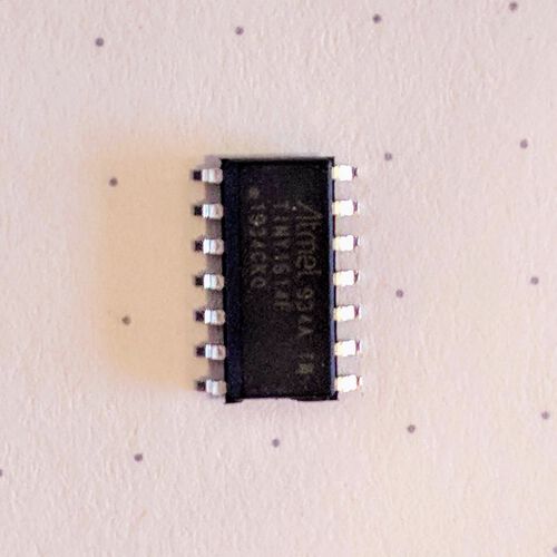
This made me realize that I’d need an ATtiny1614, since it totalled to 13 pins (and the ATtiny1614 has 14), and I wasn’t planning on using large libraries, so I figured the 16KB Flash memory of the ATtiny1614 would be big enough.
FYI | From now on we have to start using the Fab Lab Inventory List so we can find out ourselves what electronic components are available (the electronics section starts at “Digi-Key”, a bit beyond half of the full sheet).
Even though I knew what I schematically wanted to connect to 13 of the ATtiny1614 pins, those weren’t all of the components required on the board; resistors and capacitors would be needed for example.
- Each LED needs a resistor. Looking at the LEDs available from the inventory, such as this red one, I calculated the resistor value needed:
R = (V_power - V_f)/I_f = (5 - 1.8)/0.01 = 320Ω. However, I had read somewhere that using the exact value could result in an LED that was too bright. During the “Electronics Design” week we’d used a 5kΩ resistor, which was still fine. I therefore decided to go for a 1kΩ resistor this time. - The ATtiny1614 needs a capacitor to remove noise from the power loop. I used the same 1μF value as we did for the ATtiny412 before.
- Each sensing pin of the capacitive touch sensor would need a resistor. I choose 1MΩ, since the CapacitiveSensor library mentioned that would be good for direct touch.
- Each sensing pin of the capacitive touch sensor should use a small 100pF capacitor to stabilize the readings.
- The two pins connected to the ATtiny1614 for the external switches should have resistors, but I figured I could use the ATtiny’s internal pullup resistors for this (all I/O pins of the ATtiny1614 have this).
- Two outgoing pins for the capacitive touch sensors.
- Four outgoing pins for the external switches.
This all combined to the following components needed on my board:
| Component | Full Label in KiCad | Reference | Specific Orientation | |
|---|---|---|---|---|
| ATtiny1614 | Microcontroller_ATtiny412_SSFR | U1 | Yes - Dot in one corner | |
| UPDI | Conn_UPDI_01x02_Male | J1 | Yes | |
| FTDI | Conn_FTDI_01x06_Male | J2 | Yes | |
| 01x02 Male connector | Conn_01x02_Male | J3 | Yes | |
| 02x02 Male connector | Conn_01x04_Male (I used a 01x04 symbol, but 02x02 footprint) | J4 | Yes | |
| Hall effect sensor | Sensor_Hall-Effect_Analog_A1324LLHLT-T | U2 | Yes | |
| LED Red | LED_1206 | D1 | Yes - Green line on top pointing to cathode | |
| LED Blue | LED_1206 | D2 | Yes - “T” shape on bottom pointing to cathode | |
| Capacitor 1μF | C_1206 | C1 | No | |
| Capacitor 100pF | C_1206 | C2 | No | |
| Capacitor 100pF | C_1206 | C3 | No | |
| Resistor 1kΩ | R_1206 | R1 | No | |
| Resistor 1kΩ | R_1206 | R2 | No | |
| Resistor 1MΩ | R_1206 | R3 | No | |
| Resistor 1MΩ | R_1206 | R4 | No |
Schematic in KiCad
I looked up the pinouts from the ATtiny1614 datasheet and the even more elaborate “Arduino” version from the megaTinyCore website:
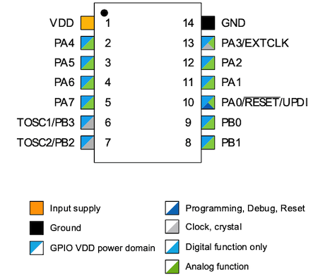
With these pinouts and and knowing what sensors to add, I opened KiCad and started setting up my schematic, following the steps I wrote down for the “Electronics Design” week.
I only had a few requirements for how to attach the different components to the ATtiny1614:
- The LEDs should be connected to PWM pins, and I wanted them both to be at the same (physical) side.
- Seeing that all the ATtiny1614 pins (apart from TX and RX) are both digital and analog, I could connect the Hall effect sensor (and capacitive touch sensors) to any remaining pins.
- I wanted the three pins I needed for the capacitive touch, and the two needed for the external switches to both be on the same physical side.
I wasn’t able to find a symbol for the 2x2 male connector that I wanted to use for the external switches in the fab library. I did see that there was a 2x2 footprint though. I therefore figured I’d just use a Conn_01x04_Male connector as the symbol in the schematic, and assign the 2x2 footprint to it later.
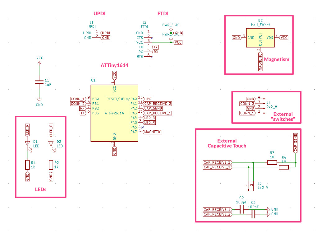
As mentioned before, the PCB Schematic from Jacopo Dimatteo was really helpful to set-up my own two capacitive touch sensors.
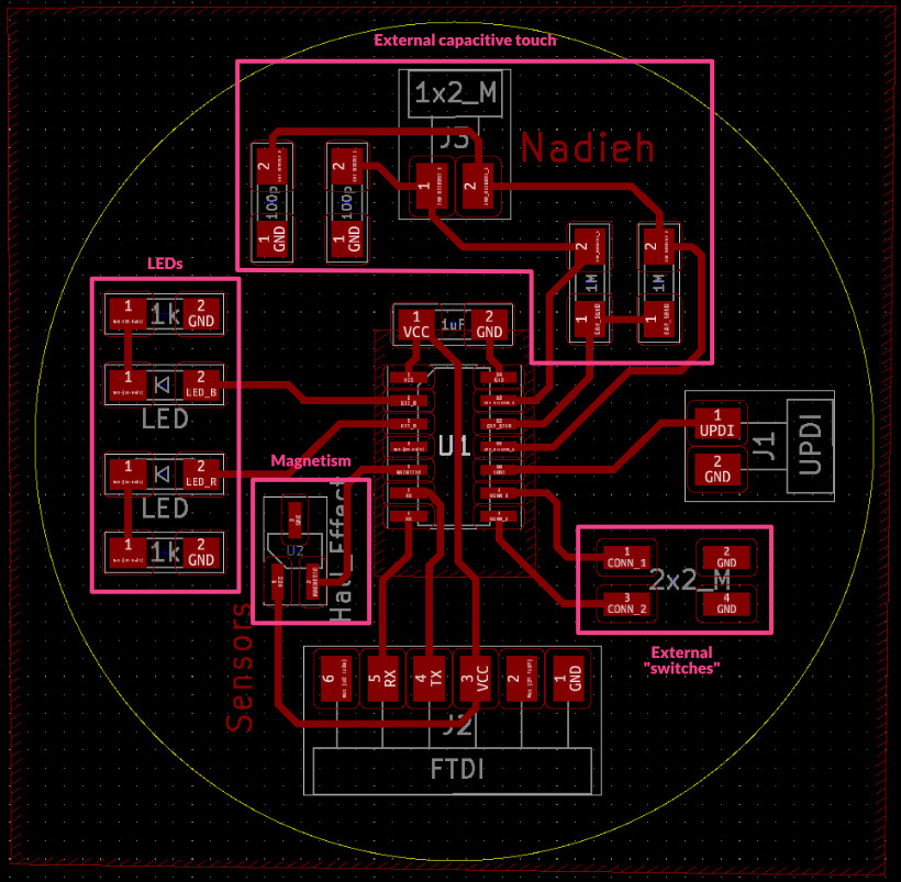
Below is the schematic that I created, highlighting the three areas of the sensors and the LEDs (this is after having moved around some components on the ATtiny1614 pins after fiddling with the component placement in the PCB layout, and fixing the error in the Hall Effect sensor):
Editing a Symbol
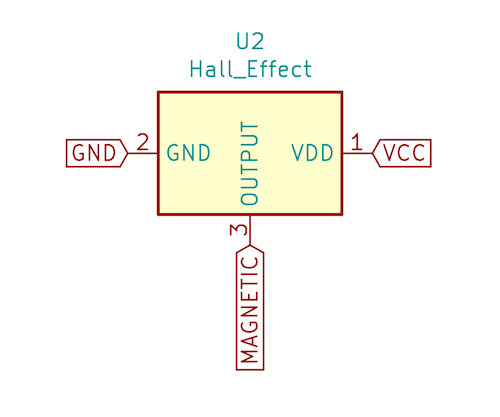
Originally, my schematic included a wrong Hall effect sensor symbol. The footprint had the GND and OUTPUT pins switched, which I only discovered after trying to test the sensor on my finished board. I’ll get into the details farther below, but I figured out that the symbol from the fab library in KiCad had the numbers of the GND and OUTPUT pins switched; they should be 3 and 2, respectively, not 2 and 3 which is how it was originally.
Let me explain how you can update a footprint when needing to do such a simple change. In the main window of KiCad, click on the Edit Footprint icon along the row of icons, next to the Schematic Layout Editor icon.
This will open a new window showing a list of all the libraries. Select the library with the footprint you want to change, fab in my case, and open it up to find the exact symbol (click the down arrow mark). Double click the symbol, which will open it up on the right.
In my case I had to update the number of the GND pin to 3 and of the OUTPUT pin to 2. I therefore hovered over the 3 and pressed E to see Pin Properties, in which I could change the Pin number. I did the same for the OUTPUT pin and saved the results. That was it!

I then went to the PCB layout editor, imported the changes from the schematic, and had to redo some of the traces of the Hall Effect sensor.
However, since I only realized this mistake after I had already milled and soldered my board, these changes aren’t reflected in my actual board, only in the final KiCad files I share at the end.
PCB Layout in KiCad
Next, I had to wrangle the rat’s nest of components in KiCad’s PCB Layout Editor into a functional board. Reading through my documentation of the “Electronics Design” week, I thankfully saw to first set the Design Rules (which I’d completely forgotten otherwise).
I saw that the FTDI was best placed at the bottom of the ATtiny1614, otherwise the RX and TX legs would be crossing. I slowly started moving the other components around, laying everything out in their functional pairs (both LEDs and their resistors together, all components for the capacitive touch sensor together).
I used a copper pour for the GND lines on this board as well (as I’d done for my board from the “Electronics Design” week). However, the Hall effect sensor was so small that it’s GND pin was closed off from the rest of the GND plane. Thankfully, I could create a trace from the GND pin to the nearest GND pad to fix it (this is based on the wrong symbol-to-footprint version of this sensor).

After having everything roughly in a good spot, I saw that I could try turning this board into a circle to make it just a little bit more interesting than a rectangle. At first I made the circle too small and had problems with not all of the copper being connected for the GND. Somehow I always overestimate the size of the boards in KiCad, so when I saw that I’d made the diameter only 4cm, I figured I could easily go to 5cm and have room to more comfortably place the components.

A final note on the PCB layout. While trying to create the interior file (the edge cuts basically) by making a graphic polygon, I noticed that it can truly only do polygons, not circles. Thankfully, I found a note on the KiCad forum to simply draw a graphic circle with half the final radius. Next, press E while hovering over its line and set the line thickness to the full radius and the result will be a completely filled circle.

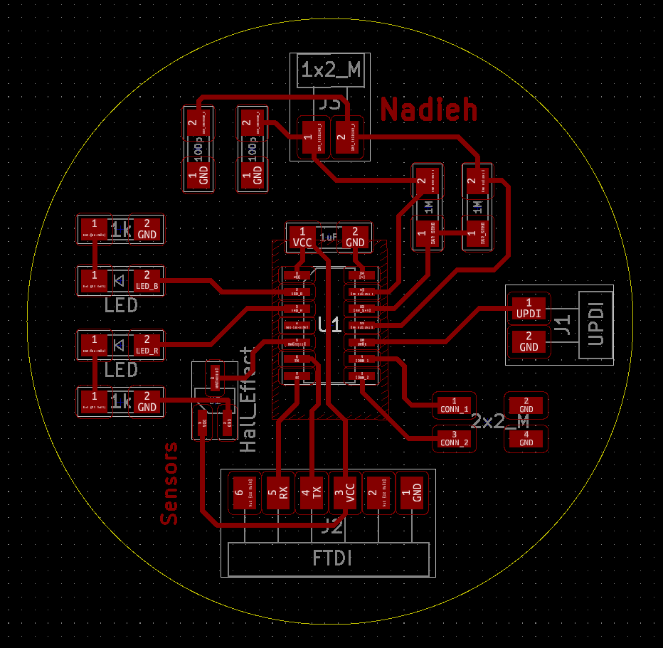
Below you can see the final PCB layout designs for my board (including the correction for the Hall Effect sensor) where I’ve outlined the areas for the three sensors and two LEDs:
I exported the F.Cu (traces) and Dwgs.User (interior) layers as SVGs. I opened up the the traces file in Adobe Illustrator to black out the circle to the edges completely (and added a tiny puzzle piece logo for fun). Then made sure to export it with a resolution of 1000dpi.

I tested the traces PNG file in mods which looked fine (after inverting).
Because the interior SVG was already good as-is, only having to be inverted, I loaded that into mods to check as well. However, the resulting toolpath of the circular outline was extremely crude (image below left). I therefore used Illustrator to save it straight out as a 1000dpi PNG file. Loaded into mods (and inverted) this created a good circular toolpath (image below right):


Milling & Soldering the Board
Back at the lab on Monday I followed the steps from the “Electronics Production” week to set-up for the milling.
Usually I push in the 0.4mm milling bit far into the head to make sure that it won’t hit the copper plate as I move it to the origin. However, this time the milling bit had a blue ring around it which prevented me from pushing the milling bit in as far as I usually do.
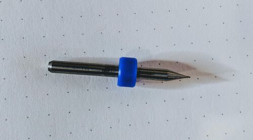
Henk said it was fine, so I started mods, replaced the 0.8mm milling bit with the 0.4mm one (the milling head was high in the air at that point, it was in that position already, I did not move it with the UP and DOWN buttons). However, when I updated the origin in mods and pressed Move to origin, the milling head moved all the way down. Even worse, I could see that it moved farther down than the top of the copper plate!! (⑉⊙ȏ⊙)
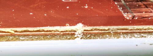
When I noticed I immediately pressed VIEW and then held the VIEW and the ON button together to try and pause the machine, which thankfully worked, but not before the milling bit had already broken and buried itself a little into the top copper plate a little (╥﹏╥)
I’m still not completely sure what I did wrong. I did see that Henk (who of course came to help out while the milling bit was starting to bury itself into the plate), moved the milling head upward with the UP button first. And when I redid a Move to origin, the milling head didn’t move down nearly as far anymore. So perhaps next time I should first move the head farther upward with the UP button before pressing Move to origin?
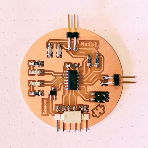
Having gotten a new milling bit, thankfully nothing else went wrong during the process and I ended up with a nicely looking round PCB (Gosh, this circle only just fitted in the space that was still available on the copper plate, but I’d made sure to measure it beforehand)


I gathered all of the components that I’d need. Except for the two LEDs, since I wouldn’t know which would be the blue one and which the red one if I put them side by side. I only grabbed each LED once I was ready to solder it.
While soldering on the ATtiny1614 (as the first component) I was really happy that I’d made so many of the traces under its legs go straight outward, which made it a lot easier to place both the tip of the soldering iron and the solder itself. After I’d successfully soldered the ATtiny1614 on the board I figured the worst part was over.
Although no mistakes happened, I did have some issues to solder on the two 01x02 Male connectors and the FTDI connector. Somehow these are always placed a little crooked for me, pointing down a little which creates a bit of space between the legs and the pads requiring quite a lot of solder to make the connection. Maybe I should try to solder these while holding them with my hand instead of the tweezers so I can press them down better while soldering the first pad? It worked for the FTDI connector at least (I didn’t try this for the other two).
The little puzzle piece icon in the lower right came out really well! Especially when compared to how crude the tiny graphical circles looked on my previous board. I think it’s because I made the stroked thicker around this puzzle piece, which helped mods create better toolpaths.
Using My Sensors
With the board seemingly done I first did a few continuity tests with a multimeter to check if all the traces and pins were connected correctly. This all checked out fine.
I therefore connected my board to my laptop using the FTDI and UPDI, opened up the Arduino IDE and started with the simple Blink example, adjusted for two LEDs, to see if my LEDs worked.
//Cross blink the two LEDs
#define pin_led_r 1
#define pin_led_b 0

void setup() {
  pinMode(pin_led_r, OUTPUT);
  pinMode(pin_led_b, OUTPUT);
}//void setup

void loop() {
  digitalWrite(pin_led_r, HIGH);
  digitalWrite(pin_led_b, LOW);
  delay(1000);
  digitalWrite(pin_led_r, LOW);
  digitalWrite(pin_led_b, HIGH);
  delay(1000);
}//void loop

Naturally, since the LED on our previous board wasn’t connected to a PWM pin (Pulse Width Modulation), and these two were, I opened the Fade example next and adjusted it to cross-fade the red and blue led:
//Cross-fade the two LEDs using PWM
#define pin_led_r 1
#define pin_led_b 0
int brightness = 0;
int fadeAmount = 5;
int n_max = 255;

void setup() {
  pinMode(pin_led_r, OUTPUT);
  pinMode(pin_led_b, OUTPUT);
}//void setup

void loop() {
  //Set the brightness
  analogWrite(pin_led_r, brightness);
  analogWrite(pin_led_b, n_max-brightness);

  //Change the brightness for next time through the loop:
  brightness = brightness + fadeAmount;

  //Reverse the direction of the fading at the ends of the fade:
  if (brightness <= 0 || brightness >= n_max) {
    fadeAmount = -fadeAmount;
  }//if

  delay(30);
}//void loop
Magnetism
With the two LEDs working I figured the Hall Effect sensor was the easiest sensor to start with. Since it was already on my board, I only had to read its value with analogRead and output it to the Serial port.
//Read out the Hall Effect sensor
#define pin_hall 3
int sensor_value_magnet = 0;

void setup() {
  Serial.begin(9600);
}//void setup

void loop() {
  //Get the value from the Hall effect sensor
  sensor_value_magnet = analogRead(pin_hall);
  Serial.println(sensor_value_magnet);

  delay(30);
}//void loop
However, the only value that the sensor returned was between 198 - 202, no matter if I moved in a magnet σ_σ
I wasn’t able to find anything online about a “Hall Effect sensor always giving the same value”. I checked Adrian Torres' Ardianino website to see if I was missing anything from the code. But it seemed the same. I then checked the board schematic from the simple ATtiny412 example from Neil and noticed that GND pad was not in the same location as my board?! ಥ_ಥ
The GND and OUTPUT pin were switched around for me. O no…
I looked up the datasheet of the A1324LLHLT-T sensor too see its schematic, and yup, the GND pin was on the side with only one pin.
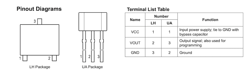
I checked my schematic in KiCad again, but that looked correctly connected. Well, except that the pin numbers of the connections were wrong. In the symbol GND was connected to 2 and OUTPUT to 3, but the datasheet showed that this should be reversed. Darn it! The fab library’s symbol was wrong!
Oh well, I guess we’re all human and mistakes can happen ¯\_(ツ)_/¯ I’m just happy that we even have a Fab Academy library to begin with!
I looked at my board and saw that it wouldn’t be too hard to break up some connections and create soldering bridges to make new connections to fix the issue: I scratched away part of the trace from the top pin of the sensor and instead made a soldering bridge to the GND area to the left of it (so happy I decided to go for a copper pour for the GND, making this really easy). I created two cuts along the left and top side of the sensor to remove its connection to GND and instead created a soldering bridge from the copper island that I’d created (with the two scratches) to the trace running towards the ATtiny.
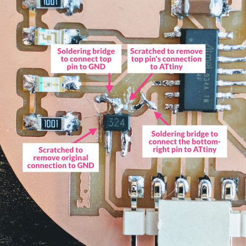
It wasn’t that pretty, but compared to some “adjustments” my boards had needed in the past, this was nothing (*≧▽≦)
. Plus, it worked! When I connected my board to power again and checked what was returned by the Serial statements it was displaying ±508-510, which changed as I moved in a magnet.
I noticed that the values would either drop below the average of ±510 (being the half of 1023, the 10-bit max value) or grew above that average as I moved the magnet around; it was responding to either the plus or minus (North / South) poles of the magnet, nice!
Instead of the Serial monitor, I wanted to use both LEDs to reveal the sensor’s values. I hadn’t picked blue and red colors for nothing! I made one color shine brighter the higher the value came above the default, and vice versa for the other LED:
//Show Hall Effect sensor's value with the two LEDs
#define pin_hall 3
#define pin_led_b 0
#define pin_led_r 1
int sensor_value_magnet = 0;
int brightness = 0;

void setup() {
  Serial.begin(9600);

  pinMode(pin_led_b, OUTPUT);
  pinMode(pin_led_r, OUTPUT);
}//void setup

void loop() {
  //Get the value from the Hall effect sensor
  sensor_value_magnet = analogRead(pin_hall);
  Serial.println(sensor_value_magnet);

  if(sensor_value_magnet >= 512) {
    //Adjust the brightness of the red led
    brightness = map(sensor_value_magnet, 512, 1023, 0, 255);
    analogWrite(pin_led_r, brightness);
    //Turn off the blue led
    digitalWrite(pin_led_b, LOW);
  } else if (sensor_value_magnet <= 506) {
    //Adjust the brightness of the blue led
    brightness = map(sensor_value_magnet, 0, 506, 255, 0);
    analogWrite(pin_led_b, brightness);
    //Turn off the red led
    digitalWrite(pin_led_r, LOW);
  } else {
    //Turn off both leds if it's measuring the ±default value
    digitalWrite(pin_led_r, LOW);
    digitalWrite(pin_led_b, LOW);
  }//else

  delay(30);
}//void loop
External Switch
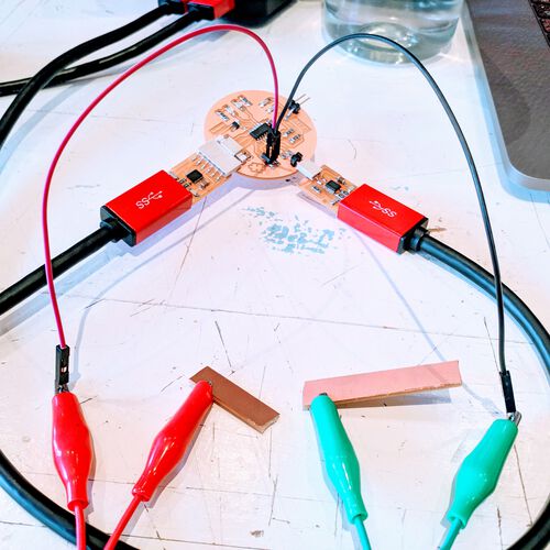
With the Hall Effect sensor working, I moved on to the external switches. I grabbed some wires, alligator clips and cut out some strips of copper plate from the left-over pile, which is could use as the “connection”.
I wrote a really simple function that checks the state of the the pin corresponding to what I’d named “switch 1” and to turn on the red LED if there was no connection, and turn on the blue LED if there was a connection:
#define pin_led_r 1
#define pin_led_b 0
#define pin_switch_1 7
#define pin_switch_2 6 //this one isn't used
int sensor_switch_1 = 0;

void setup() {
  Serial.begin(9600);

  //Switch sensor
  pinMode(pin_switch_1, INPUT_PULLUP); //use the internal pullup resistor

  //LEDs
  pinMode(pin_led_r, OUTPUT);
  pinMode(pin_led_b, OUTPUT);
}//void setup

void loop() {
  //Get the value from the switch sensor
  sensor_switch_1 = digitalRead(pin_switch_1);
  Serial.println(sensor_switch_1);

  if(sensor_switch_1 == 1) { //1 = no connection
    digitalWrite(pin_led_r, HIGH);
    digitalWrite(pin_led_b, LOW);
  } else {
    digitalWrite(pin_led_r, LOW);
    digitalWrite(pin_led_b, HIGH);
  }//else

  delay(30);
}//void loop
That went pretty easy, and was very stable. This was a great contender for a sensor to use for my puzzle pieces.
Capacitive Touch
The final sensor to try, and the most complex of all, were the capacitive touch sensors. I connected a wire and alligator clip to one of the two capacitive touch sensor connections and clipped the alligator clip to a bigger piece of leftover copper plate that I’d covered with some transparent tape (since it was recommended to have an insulating layer).
I took the default example from the CapacitiveSensor website, updating it to only have two sensors, but commenting out the second sensor.
#include <CapacitiveSensor.h>

#define pin_capacitive_1 10
#define pin_capacitive_2 8
#define pin_capacitive_send 9

CapacitiveSensor   cs_1 = CapacitiveSensor(pin_capacitive_send, pin_capacitive_1);
CapacitiveSensor   cs_2 = CapacitiveSensor(pin_capacitive_send, pin_capacitive_2);

void setup() {
  Serial.begin(9600);
}//void setup

void loop() {
  long start = millis();
  long total1 =  cs_1.capacitiveSensor(30);
  //long total2 =  cs_2.capacitiveSensor(30);

  Serial.print(millis() - start);        // check on performance in milliseconds
  Serial.print("\t");                    // tab character for debug window spacing
  Serial.print(total1);                  // print sensor output 1
  Serial.print("\t");
  Serial.print(total2);                  // print sensor output 2
  Serial.println("");

  delay(10); // arbitrary delay to limit data to serial port
}//void loop
I uploaded this to my board and watched the Serial monitor in my terminal. It returns -2 if it doesn’t detect a touch, and sadly that was all that it was returning for me, no matter if I touched the copper plate or not ⊙︿⊙
Well, what if I just read the bare value that the sensing pin returned. I wasn’t really sure if that made sense at all, since I wasn’t using the send pin to send anything, but I hoped it at least would let me show what could be returned.
#define pin_capacitive_1 10
#define pin_capacitive_2 8
#define pin_capacitive_send 9

void setup() {
  Serial.begin(9600);

  pinMode(pin_capacitive_1, INPUT);
  pinMode(pin_capacitive_2, INPUT);
  pinMode(pin_capacitive_send, OUTPUT);
}//void setup

void loop() {
  //Just a bare reading
  int sensor_cap_value_1 = analogRead(pin_capacitive_1);
  Serial.println(sensor_cap_value_1);

  delay(10);
}//void loop
I saw numbers pass by on the Serial monitor, but they seemed to be flicking between 0 and higher values. It was all going way too fast for me to read though, so I increased the value of the final delay to delay(500);
Well, the numbers were changing and they did seem to respond to touch, but it was pretty erratic.
Then I remembered that in my initial exploration of capacitive touch sensors, I’d also found a page that didn’t use the CapacitiveSensor library, but used the general principle of capacitive touch instead: to see how long it would take for the sensor (receive) pin to read as HIGH after the send pin had been put to HIGH.
#define pin_capacitive_1 10
#define pin_capacitive_2 8
#define pin_capacitive_send 9

void setup() {
  Serial.begin(9600);

  pinMode(pin_capacitive_1, INPUT);
  pinMode(pin_capacitive_2, INPUT);
  pinMode(pin_capacitive_send, OUTPUT);
}//void setup

void loop() {
  //Set the send pin to low and wait a bit for
  //the copper plate to discharge
  digitalWrite(pin_capacitive_send, LOW);
  delay(10);

  //Mark the start time of when the send pin sets
  //the copper plate to high, charging it
  long start_time = micros();
  digitalWrite(pin_capacitive_send, HIGH);

  //Keep hanging in a while loop while the receive pin remains low
  while(digitalRead(pin_capacitive_1) == LOW);

  //Once it's out, check how much time that took
  long sensor_value = micros() - start_time;
  //Short times means no touch, long times mean touch
  Serial.println(sensor_value);

  delay(500);
}//void loop
Again, something was coming through, and the values did go upward when I touched the plate, but they jumped around wildly. Going from a number in the thousands to almost zero on the next.
I then remembered that on another page about capacitive touch I’d come across the concept of smoothing which comes down to a running moving average. I added the smoothing code to the loop function instead of the Serial.println(sensor_value); line:
  // subtract the last reading:
  total = total - readings[readIndex];
  // add the sensed value:
  readings[readIndex] = sensor_value;
  // add the reading to the total:
  total = total + readings[readIndex];
  // advance to the next position in the array:
  readIndex = readIndex + 1;

  // if we're at the end of the array wrap around to the beginning:
  if (readIndex >= numReadings) readIndex = 0;

  // calculate the average:
  average = total / numReadings;
  Serial.println(average);
And finally when I uploaded my new sketch did the values stop behaving so erratically; about 120 for non-touch and >200 for touch (for the largest piece of copper plate that I was playing with).
However, the values were moving up and down very slowly. I had to keep my finger on the plate for several seconds before the value had risen to >200, and it took several seconds before it had moved back down to ±120 after I removed my finger.
That wasn’t right… I’d seen enough videos of this system to know that it should be near instantaneous (e.g. see the final gif on Jacopo Dimatteo’s documentation).
Perhaps the capacitor value of 100pF that I’d connected from each sensor to GND was too high? Was the charge slipping away too slowly? To test this I desoldered one of the two capacitors from my board using a hot air gun, but sadly this only changed the measured value, but not the speed of change σ_σ
I was thinking of less and less likely options by now, but perhaps the value of the 1MΩ resistor wasn’t right for my board? I was curious to see what would change for different resistor values. However, I did not want to desolder and solder a bunch of resistors on my board. I therefore created a simple set-up of one capacitive sensor using my Arduino with a 1MΩ resistor:

But it was just as slow!! What was going on!? (°Д°) I’d seen videos of this set-up, and they reacted instantaneous. Even using a lower or higher value resistor made no noticeable change in the reaction speed.
I looked at that final delay(500); line at the end of my code. Perhaps if I sped that up again to see more values per second? Maybe that would give me some clue?
Testing the touch sensor again with a delay of only 10 and it worked!! It was changing values almost instantly upon touch and release! The values also went up a lot higher than before. I even added a bit of plastic tape on top of the copper plate again to make sure that the values didn’t jump up into the tens of thousands. It was also able to spot if I touched the plate with just the tip of my finger of my full finger:
Damn, I can’t believe that long delay() had been the culprit! ( ̄□ ̄)
For the heck of it, I switched the resistor on the breadboard for a 10MΩ one, because I’d read that these would be able to sense a human from farther away. And that was exactly what I was seeing, with the sensed value increasing as I came closer, and jumping up into extremely high values on a touch (even through the tape):
Knowing that it had been the long delay that had been the issue of the slow response, I hooked up my own circle board again, and thankfully it responded with the same speed as the Arduino!
With the touch sensor finally returning steady (enough) values, I wanted to hook up the second touch sensor as well. It took me some time to figure out how to work with (multidimensional) arrays in Arduino/C so I could use the smoothing technique for both sensors with the same function.
A Slide-Touch Sensor
It was time to try and recreate that sliding touch sensor that I’d seen before. I grabbed a long thin strip of copper and used a ruler and knife to scratch a diagonal line from one side to the other. I eventually also soldered two female-male wires to the ends to connect them to my board (but at first I simply used alligator clips).

I checked the sensor values from both sensors as I moved my finger across the “slider” and there seemed to be some potential. With the values changing in the opposite direction as I moved my finger back and forth. I adjusted my code to make the red or blue LED shine brighter depending on the values of both sensors:
However, although it’s definitely working as a touch/no-touch sensor, I’m not so sure if the sliding is truly working, haha. Because I can try the same code again at a later time, and the values reported can be widely different when touching, and can jump around much more too. I’d already read that capacitive touch sensors are heavily affected by things such as temperature and humidity and more, perhaps this is what make the sliding work better or worse?
Or perhaps it just seems to slide because I’m moving my hand about as fast as the charge in the copper rises? Oh well, at this point I’m giving up in trying to understand this further, hehe, the end of the week is here.
Nevertheless, I’m happy that I got two touch sensors to work! However, simply using the method of a switch to test if a puzzle piece is being placed seems much more reliable and easy than using capacitive sensors (*^▽^*)ゞ
FYI | I tried to investigate why I couldn’t get the CapacitiveSensor code to work when I started with the capacitive touch sensors. I first uploaded it to the Arduino, since it was created for Arduino, and saw that it worked. After I uploaded the same code to my circle board it also worked! I then remembered that in the beginning I’d used clear tape on my copper, but that I’d abandoned that somewhere at a later stage of the debugging. I was now testing the code with non-taped copper. Hmmmm…. I added a new layer of tape on top, touched the copper and nope, the values remained on “non-touching”. I guess the documentation really meant that a 1MΩ resistor needs direct touch even without an insulating layer?
All Sensors Combined
Now that I’d finally had all three types of sensors working I combined the code of each into one so I could use all sensors with the same code. There is a hierarchy to the importance of the sensors: If any of the switches are activated, the LEDs will respond to that and ignore the magnetism and touch sensors. If no switch is activated the program will check if a magnetism value is recorded that’s different (enough) from the base value. If yes, then the LEDs will glow based on the magnetism measured. Finally, if no switch and no magnetism is sensed, it will check for a touch action of either capacitive touch pads. If either of these values is different (enough) from the base value, the LEDs will change their brightness based on those values.
You can see all of them in action, successively, in the video below; switch, magnet and finally, touch:
Reflections
Although I’ve been thinking a bit about my final project throughout all the weeks, this was the first week since “Computer-Aided Design” (week 2, while we’re now in week 11) that I’ve truly been working on an aspect of my final project; figuring out what input sensors to use. I’m happy that I (seem to) have figured out what system to use, solving one tiny part of the puzzle (pun intended ◕‿◕ )
What went wrong
I somehow managed to bury one milling bit into a copper plate and brake it…
The second thing that went wrong was the Hall Effect sensor that was wrongly connected; having the GND and OUTPUT pins switched. This was due to an error in the symbol of the sensor in the fab KiCad library. I guess a lesson learned is that it could be a good idea to check the KiCad symbol pin connections of the more exotic components on the board with their datasheet.
Thankfully, it wasn’t difficult to “fix” these connections on my actual board, and my findings helped one fellow student to make updates to her board schematic in KiCad before she was going to mill it.
The final thing that went wrong for a while was that my capacitive touch sensing code wasn’t working well. It started out not working at all, then became widely erratic, then way too slow. And eventually it was a silly delay() that I’d set too long that was the reason for it all ✖‿✖
(and some clear tape that was apparently too much).
What went well
I’m really happy that all of my sensors worked! That I’d come up with the design, requirements and schematic on my own (with the help of “the internet” of course), and that it worked! (๑•̀ㅂ•́)ง✧
I now know that using a simple “switch” concept to measure which puzzle pieces are placed on the board should do the trick.
What I would do differently
Like I said above, it would’ve been smart if I’d checked that datasheet of the non-straightforward components in KiCad (e.g. the Hall Effect sensor and the ATtiny1614), but on the other hand, it’s also not wise to distrust everything I guess.
Wrapping up
During the weekend, while I was wrapping my head around the design of my board, I was quite anxious “would I be able to get it right myself?", “would I mess up the wiring of the capacitive touch?" I checked, and re-checked everything so often. But in the end, when the sensors were working, it was really cool to be able to work with the board that I’d made myself from scratch! Really rewarding! And really fun to play with (^▽^) (although I think that designing a board, milling and soldering it will never be something I’ll look forward too).