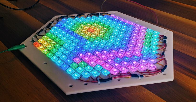
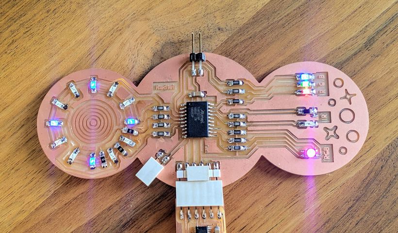
In this Output Devies week I went all out with LEDs! From a simple RGB LED, to creating my own RGB “pixel” with separate red, green, and blue LEDs, having fun with Charlieplexing. But the BIG thing I worked on this week was to fill a hexagonal shape with light. Using lots of wires, stripping, and soldering, on a hexagonal grid of NeoPixels, which are RGB LEDs which can be programmed separately (using only one microcontroller pin!).
Assignments
Our tasks for this week are:
- Group assignment: Measure the power consumption of an output device
- Individual assignment: Add an output device to a microcontroller board you’ve designed, and program it to do something
Hero Shots
Showing some final results of my LED stuffed board and NeoPixel grid the tl;dr and hopefully showing you why the rest of this very long blog could be interesting to read (⌐■_■)


Playing with Output Devices
The “instruction” day at the Waag was very short this time. Henk showed us several really cool small project done with light, such as a whole set of Trippy Waves Boards that react to your hand moving across them due to an infrared LED and sensor on it:
And another board with a line of LEDs which seemed to blink randomly, but when waving it back and forth, it spelled “Hello World”. And the final example that I found to be very cool was a tiny board with, maybe, 100+ LEDs all next to each other in a grid on which you could play Tetris!
After these examples we were free to work/play with our group assignment and try to measure the power consumption of an output device.
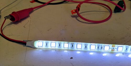
It so happened that Henk had ordered a 5 meter long LED strip of NeoPixels for me to use in my final project, specifically the WS2812E. The packaging said that this strip was 90W, a lot of power! Running at 5V that meant that the current would be I = P/V = 90/5 = 18A. I had a strip of 60 NeoPixels per meter, thus the current per NeoPixel was 5 * 60 / 90 = 60mA (which you can also find in the datasheet of the WS2812 LED, using 20mA per R, G & B).
The NeoPixels need three connections: 5V, GND and a DATA line, the latter of which is used to program the LED strip with. Because the strip requires so much power, I couldn’t just connect the full strip to an Arduino as I’d done with the tiny and medium NeoPixel ring that we’d used during the “Mechanical & Machine” week.
![]()
Thankfully, I had brought an 5V / 8A adapter with me. Theoretically this wasn’t enough to power the full strip, but I figured I could at least try for a bit. I didn’t have a proper female Jack connector to connect the power supply to the LED strip. I therefore used an SMD female Jack connector and soldered two thin wires to the GND and 5V side (I used a multimeter to figure out which metal part was what). It was flimsy though.
I loaded a simple NeoPixel program on my Arduino (based on what I’d used before) that would create a rainbow along the strip:
#include <Adafruit_NeoPixel.h>
#define pin_NEO   13
#define ledCount  300
Adafruit_NeoPixel strip = Adafruit_NeoPixel(ledCount, pin_NEO, NEO_GRB + NEO_KHZ800);

void setup() {
  strip.begin();
  strip.show(); // Initialize all pixels to 'off'
}//void setup

void loop() {
  //Show the rainbow
  for(int i = 0; i < ledCount; i++) {
    int Hue = round((float)i/(float)ledCount * 360);
    setHSV(i, Hue, 255, 255);
  }//for i
  strip.show();
}//void loop
I then connected the GND of the NeoPixel strip to the power supply (with alligator clips), the DATA to pin 13 on my Arduino and finally the 5V to the power supply. The NeoPixels turned on, but they were flashing in all colors. I then realized that I should also connect the GND of the Arduino to the GND of the NeoPixels! After adding another set of alligator clips and wires I was looking at a rainbow strip (ノ◕ヮ◕)ノ*:・゚✧
![]()
In retrospect I wonder if this was a smart move overall. I should’ve investigated the NeoPixels more thoroughly before connecting it to a power supply, especially one that wasn’t able to deliver the maximum power that the NeoPixels could ask. I’ve since read that generally, because not all pixels are turned on fully, you can assume that each NeoPixel will be using 20mA of current instead of the full 60mA. That would make the power consumption of the full 5 meters 300 * 0.02 = 6A in total, which was something my power supply could handle.
Furthermore, there’s quite the voltage drop across 5 meters of NeoPixels, thus even with each NeoPixel set to fully on in the program, if I’ve understood this correctly, the strip would still not be using the full 90W of power, because the voltage will have dropped along the strip, thus each NeoPixel wouldn’t even be able to get the maximum 60mA.
And finally, my 5V / 8A adapter, bought from the same company as the NeoPixels and meant for LED strips specifically has over-power, over-voltage, over-current and short-circuit protection.
This short-circuit protection came in handy only a few minutes later when I’d disconnected the NeoPixel strip (thankfully) and wanted to quickly type something on my laptop while the naked wires of the Jack connection were still laying on the table right below me. Apparently my arm moved the two wires together, which I didn’t notice until I saw smoke rising right in front of my nose!!! (⑉⊙ȏ⊙)
I looked down and saw that the 5V and GND wires had touched and were now melting together! I quickly jumped from my chair and unplugged the power adapter.
![]()
That was a bit scary and definitely made me much more cautious about wires from then on.
I was definitely curious to find out how much current the NeoPixel strip was using. I grabbed a lab power supply with which you can control the voltage and current (and measure it at the same time), which Loes had used to power the EL Wires with on our unfolding lamp during the “Mechanical & Machine” week. Together with fellow students Loes, Lucia and Nicole we connected a tiny 24 LED NeoPixel ring to my Arduino and the power supply (as a reminder, the power supply itself turns on with the round button in the lower left, but to actually set a voltage/current through the wires you need to press the on/off rectangular button).
![]()
We set the voltage to 5V and started with a very low current of only 0.1A. When we turned the power on, we saw that the voltage used was much lower than 5V. Loes investigated why this could be the case and found an interesting page that explains that LEDs are run by the current going through them, not so much the voltage. And I think this reduced voltage could be due to the relationship between the voltage and current of an LED (I drew a tiny chart about the voltage drop in the “Electronics Design” week).
I reprogrammed the NeoPixel ring to be fully on, with R, G and B at 255, the maximum value.
//A simple function to turn each NeoPixel fully on (white)
void whiteLights() {
  for(int i = 0; i < ledCount; i++) {
    strip.setPixelColor(i, 255, 255, 255);
  }//for i
  strip.show();
}//void whiteLights
When capping the power supply to 5V / 0.8 A it actually used 4.11V / 0.8A. When increasing the current to 1A the NeoPixel ring used 5V / 0.824A, this implies a power usage of 5V * 0.824A = 4.12W. Theoretically the NeoPixel ring should use 0.06 * 24 = 1.44A, so we were confused as to why it wasn’t. Not that it wasn’t functioning well enough, the ring was so bright that it was painful to look at.
![]()
Although the video doesn’t capture the colors well, but when I turned the maximum current of the power supply down to 0.1A the NeoPixel ring turned red. When I increased this max cap back up to 1A the ring turned from dim red to bright white:
I tried to investigate a little for this documentation if the jumper wires that were connected from the power supply to the NeoPixel ring were the reason. I think that they might’ve been too thin, combined with the alligator clips and connections, which was creating too much resistance for the maximum current to run through? However, I wasn’t able to find a conclusive answer.
Only turning on the red, or green or blue parts of each NeoPixel resulted in 0.288A being drawn by blue and red, and 0.286 by green:
![]()
![]()
These separate colors should be able to use 0.02A * 24 = 0.48A, which we’d already seen could be handles by the wires. Was it the resistance in the wires and connection points then?
Nicole had found that you could use the left and right arrow buttons below the turning knob to choose which significant digit to adjust of either the voltage or current. We therefore did a test where we capped the current to only 0.001A. This resulted in only red LED of the first 9 NeoPixels being turned on just a little:
![]()
We then moved on to the full 300 LED 5m long NeoPixel strip. We started with capping the current to 1.4A, which resulted in the strip using 3.88V / 1.4A and the light turning from white at the start to green in the center due to the voltage drop:
![]()
Which I think is because the blue LED drops out first, since it requires the highest voltage to work (when checking the datasheet of the WS2812):
![]()
When turning the current up to the maximum that the power supply could handle, 3.1A, the NeoPixel strip was using 5V / 2.291A, while still looking green on the inside. Lucia then suggested to try and power the LED strip from both sides. A few alligator clips and wires later, and the strip was drawing the full 3.1A that the power supply could deliver (it thankfully also has over-current protection)
![]()
Having reached the max of the power supply, we couldn’t test what the full strip could draw right now. We therefore tried to experiment a little with only turning on some of the Neopixels, such as only the first 150 or first 50, or every 5 NeoPixels.
With 150 NeoPixels turned on the NeoPixels were indeed brighter, and with only 50 turned on they were incredibly bright (using 5V / 1.8A). But no matter what we tried, we never got the NeoPixels to draw the maximum current that we expected it could take.
![]()
- Intermezzo - | At home my partner has a power supply that can go up to 10A, and thick wires that can handle 60A. During the evening we therefore hooked up the NeoPixel strip again to see what current it would draw.
With all pixels on at full brightness, being supplied power from both ends, it was drawing 6.86A. Still not near the 18A that was the max. But perhaps for that we should’ve supplied power to the strip at every meter to counter the voltage drop? Although there wasn’t any noticeable color change towards the middle, the LEDs were extremely bright and painful to look at.
![]()
- Intermezzo end -
Nicole, Lucia and I wanted to try a completely different LED strip and found one laying on a table. It looked similar to the NeoPixels, however it needed 24V and it wasn’t programmable; there was only a power and ground line attached to it. We forgot to measure the length, but I think it was about 1 meter long.
Setting the power supply to 24V and 1A we saw that it was using 24V / 0.547A, which is a power of almost 11W. Lucia then turned down the voltage on the power supply and we saw that the LEDs still worked below 24V, and turned completely off if it dropped to 15V (or lower).
And that was enough measuring for me. I really wanted to start thinking about what board to create! (^▽^)
I didn’t look into motors this week, but thankfully I’ve already had the chance to get some experience with it when I used and programmed a Nema stepper motor for the “Mechanical & Machine” week.
Designing my Board
For this output week I wanted to focus on turning the 5m long strip of NeoPixels into something that I’d need for my final project, the puzzle. However, I was also intrigued to play with light in different ways. Not too difficult, I expected that the NeoPixel grid would take a lot of time already, but just some fun things.
Choosing the Output Devices
After having used LEDs in separate colors I figured it would be fun to try using an RGB LED, which had all three color in one. The tiny little component requires three connections to a microcontroller.
Henk suggested to try and create an “RGB” pixel myself from using a separate red, green and blue LED, which seemed interesting too.
I also found it fun to implement the same principle as the Trippy RGB Waves example that Henk had showed before, by using and IR LED and IR phototransistor so you could wave over the board and the lights would change.
And finally, I wanted to try Charlieplexing, which is an ingenuous way of using the fact that diodes only let current through in one direction to address N*(N-1) LEDs with only N pins. This had been suggested to me in an earlier week as an option to create the lights for my puzzle board. However, the NeoPixel strip was much more suitable. Nevertheless, I wanted to try it at a small scale anyway, using 4 pins to use 12 LEDs.
All Required Components
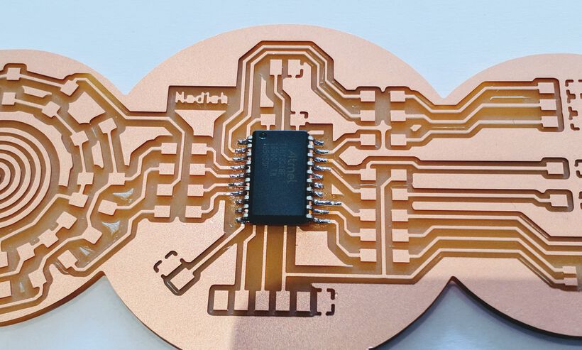
Looking at the number of pins all these LED-based ideas required, I saw that the ATtiny1614 wasn’t enough and I had to go bigger still, to the ATtiny3216, with 20 pins total.
I looked up the pinout from the ATtiny3216’s datasheet and also looked up the Arduino version of the pinout from the megaTinyCore website.
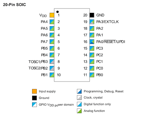

I wrote down which pins I wanted to use for what, making sure to use PWM pins for the RGB and the separate R, G, and B LEDs, and to use an analog pin for the IR phototransistor for example.
I looked up if the NeoPixels needed a special kind of pin (PWM, analog or digital). This page explains that although the NeoPixels do require PWM, you can use any kind of GPIO pin on a microcontroller, because the integrated circuit onboard each pixel does the job of providing PWM.
| Component | ATtiny3216 Pin Number | Arduino Pin Number | Note |
|---|---|---|---|
| LEFT SIDE | |||
| VCC | 1 / VCC | ||
| LED Green | 2 / PA4 | 0 | PWM |
| LED Blue | 3 / PA5 | 1 | PWM |
| Charlieplexing | 4 / PA6 | 2 | |
| Charlieplexing | 5 / PA7 | 3 | |
| Charlieplexing | 6 / PB5 | 4 | |
| Charlieplexing | 7 / PB4 | 5 | |
| TX | 8 / PB3 | 6 | Digital only |
| RX | 9 / PB2 | 7 | PWM / Digital only |
| NeoPixels | 10 / PB1 | 8 | PWM |
| RIGHT SIDE | |||
| GND | 20 / GND | ||
| LED Red | 19 / PA3 | 16 | PWM |
| Phototransistor IR | 18 / PA2 | 15 | |
| LED IR | 17 / PA1 | 14 | |
| UPDI | 16 / PA0 | 17 | |
| - | 15 / PC3 | 13 | Digital Only |
| - | 14 / PC2 | 12 | Digital Only |
| LED RGB - B | 13 / PC1 | 11 | PWM / Digital Only |
| LED RGB - G | 12 / PC0 | 10 | PWM / Digital Only |
| LED RGB - R | 11 / PB0 | 9 | PWM |
The table above already takes into account the exact pin numbers that I used for my final schematic (I moved the IR LED, phototransistor and NeoPixel connection around a little while trying to lay out the board in KiCad).
I had two pins left, and Henk advised me to try and try and use the SDA and SCL pins so I could use this board next week in the “Networking” week as well. However, there was no clear way to move other components around to make it fit; the LEDs needing PWM, the Charlieplexing pins needed to stay together, and the phototransistor needed an analog pin (while the two remaining pins, PC2 and PC3 were Digital only according to the Arduino pinout, even though the datasheet itself still shows these two pins as both analog and digital, nevertheless I wanted to play it safe).
Schematic in KiCad
I opened KiCad and started designing my board with the Schematic Layout Editor while following the steps from my “Electronics Design” documentation.
I first added the ATtiny3216 and the FTDI and UPDI connections. Next, I added all of the straightforward LEDs and (of course) their resistors. I wasn’t really sure what resistor value to use. I’d gone with 1k for my board in the Input Devices week, however, according to the specs the resistor values could go down even further, with the green LED needing the highest resistor value with an Vf of 2.1V and an If of 10mA -> (5V - 2.1V)/0.01 = 290Ω.
I was still afraid that the LEDs might become too bright, and thus decided to start with giving all the LEDs 499Ω resistor values instead (except for the IR LED which I set to 1k since I hadn’t used an IR LED before).
I knew that giving the red, green and blue LEDs all the same resistor value would not be ideal, because some colors are brighter. Neil had said that blue needed a smaller resistor value, to make it brighter, but someone on the chat mentioned that this wasn’t needed. I figured I might as well start with all those resistors at the same value and then make changes accordingly once I could see the actual LEDs next to each other.
I’d found that the IR phototransistor actually performs better with higher resistor values, and needs at a least 5kΩ resistor. I checked what I’d used for my first board during the Embedded Programming week, which was 10kΩ, and went with that this time as well.
The final, and the only truly difficult part of this board, was the charlieplexing schematic. Although I understood the idea behind it, I definitely wasn’t comfortable enough to figure out the schematic for it myself. Thankfully, I found two great tutorials showing the exact same schematic of wiring for 12 LEDs, which seemed quite logical to me when it was displayed like that. I therefore recreated it in my KiCad schematic, hoping it would work out ┐( ̄ヮ ̄)┌
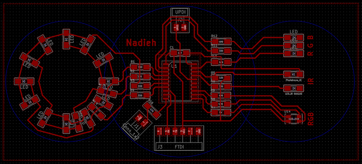
Below you can see my final schematic from KiCad. This schematic reflects my final board, including the resistor values that I ended up with (having desoldered some of the 499Ω resistors for 330Ω on my board after testing the LEDs):
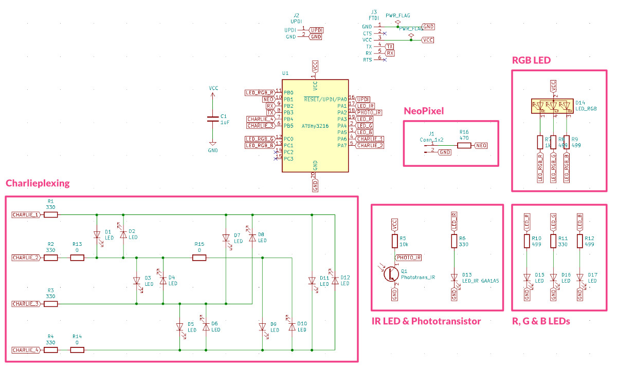
The charlieplexing section also shows the three 0Ω bridges that I ended up needing to make the traces work.
Furthermore, stupidly, having played with the NeoPixel ring during the “Mechanical & Machine Design” week, I didn’t read into connecting a NeoPixel strip, assuming it would be the same. Partly, because I was so focused on designing my complete board on the Thursday to then mill and solder on Friday. However, now doing my for the documentation I actually found out that I should’ve added a 470Ω resistor along the data line (going to the microcontroller). This can help prevent spikes on the data line that can damage the first pixel. I therefore added it to my schematic above as well, to reflect the right way of having made it even though my actual board doesn’t have it.
I didn’t come across the need for this resistor while using the NeoPixel ring, because apparently it’s already integrated into the NeoPixel rings.
Below is a table with the components used:
| Component | Full Label in KiCad | Reference | Specific Orientation |
|---|---|---|---|
| ATtiny3216 | Microcontroller_ATtiny3216-SFR | U1 | Yes - Dot in one corner |
| 01x02 Female connector | Conn_01x02_Male (I couldn’t find a female symbol in the fab library) | J1 | Yes |
| UPDI | Conn_UPDI_01x02_Male | J2 | Yes |
| FTDI | Conn_FTDI_01x06_Male | J3 | Yes |
| Capacitor 1μF | C_1206 | C1 | No |
| Phototransistor IR | Phototransistor_Infrared_PT15-21B-TR8 | Q1 | Yes - Green marking on top pointing to cathode |
| LED IR | LED_IR | D13 | Yes - Green marking on top pointing to cathode |
| RGB LED | LED_RGB_CLV1A-FKB | D14 | Yes - Triangle cutout of R pin |
| 15 LEDs - various colors | LED_1206 | D1-D12, D15-D17 | Yes - Green marking on top pointing to cathode |
| Resistors - various values | R_1206 | R1 - R16 | No |
PCB Layout in KiCad
Moving on to the PCB Layout Editor in KiCad to see if I could even untangle this utter chaos of LEDs (17 of them!) and resistors ಥ﹏ಥ
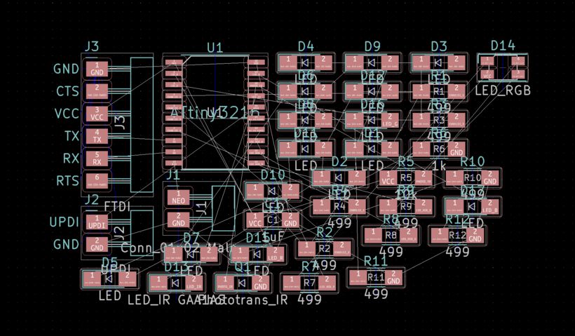
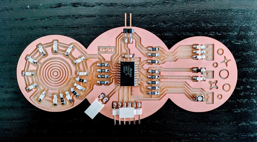
I started by placing each of the different “output” groups together; all charlieplexing LEDs and their four resistors to the left with the LEDs in a rough circle, the RGB LED with its three resistors to the right of the ATtiny, the R, G and B LED and their three resistors to the top, FTDI at the bottom, etc.

With the left side turning into a circle with the charlieplexed LEDs, I figured I could create a second circle along the right side of the ATtiny with the other LED outputs; the RGB LED, the R, G & B LEDs, and the IR LED and phototransistor, to create a symmetric board. Then I’d keep the ATtiny, all connectors and all resistors in the center.
For the “RGB pixel” that I wanted to create with the separate R, G & B LEDs I remembered how the old color television sets always had a red, green and blue long dash next to each other, and mimicked this orientation on my board as well. In retrospect I should’ve probably investigated a bit more if this orientation would also work with these LEDs as well.
I used a bunch of graphic lines to figure out exactly how to place all the LEDs to position them in a perfect circle / along the middle (you can set the end point positions of lines exactly by hovering over one and pressing E):
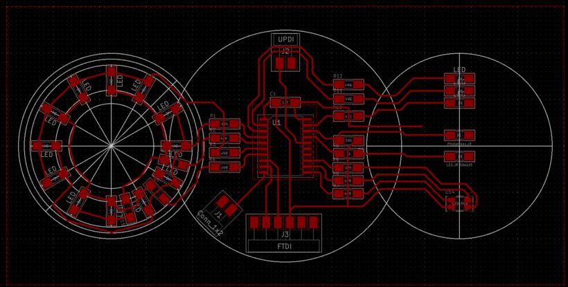
As you might be able to see in the bottom-right quadrant of the charlieplexed circle along the left of the image above, I needed three 0Ω resistors to act as bridges sadly. I do wonder if three is the smallest number possible, or if a different orientation would need fewer bridges.
As with my previous boards I created a copper pour for the GND, removing the need for creating a trace to all GND pads (plus, I’ve found that it’s now very easy to see which pads are GND when I’m trying to check connections for example). I did have a small issue where the GND of my capacitor and UPDI wasn’t connected to the general GND when using the copper pour. However, that was easy to solve by drawing an actual trace from the capacitor GND pad underneath a resistor and to the GND pad of the IR LED.
Adding some text and I was done with my PCB layout in KiCad
Note | The default text size of 1.5mm in width and height and 0.3 in thickness is just too small to be milled nicely. So increase it somewhat.
I saved the F.Cu file to an SVG and opened it in Illustrator to add some marks for fun and save it to a png (File -> Export -> Export as, don’t forget to check Use artboard and save at 1000 dpi).

For the interior file I created three circles in the Dwgs.User layer (create a graphic circle at half the radius and then set the line thickness to the full radius), saved it as an SVG, opened in Illustrator and saved straight to a png.

A quick check in mods (inverting both png files) showed proper toolpaths. I was surprised to finally see how big this board had become; 11.7mm x 5.2mm (⊙.⊙) Were the copper plates even that wide?!
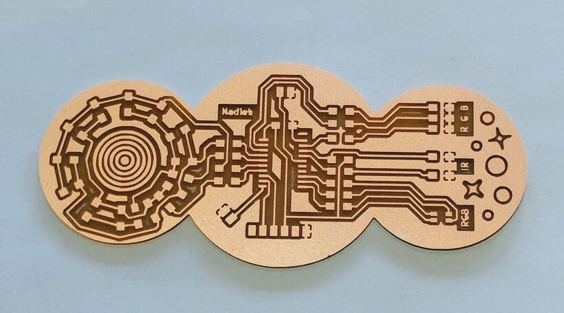
Milling & Soldering the Board
Back at the lab I saw that the boards were thankfully about 12.Xmm wide, pfew! I did need to replace the board already present sadly, although there was still room left for typical boards (e.g. a UPDI or FTDI), it wasn’t nearly enough for my monster of a board (sorry!).
I followed the steps as I documented in the “Electronics Production” week to set-up the Roland Modela MDX-20 milling machine.
I saw that the milling bit in use was one with a blue ring fixed to it. During the “Input Devices Production” week I’d had an issue with those where the milling bit moved too far down when I pressed Move to Origin in mods and had run into the copper plate.
This time I figured I would try and move to the origin without any milling bit in it. And as I expected, when I pressed Move to Origin the machine moved the milling head down first. Happy that I removed that milling bit first! Perhaps it only happens when you press Move to Origin the first time after having restarted mods? Or perhaps the first time after the machine has been placed into the “plate in the back” position again with the VIEW button?
I moved the milling head back up and placed the milling bit into it, continuing to even more finely set it’s origin to the absolute corner of the copper plate, and z-aligning it.


The milling took forever!! I remember that a typical UPDI takes about 20-30mins. I forgot to properly time this one, but I think it was between 2 and 3 hours! I’m never making such a big board again (*^▽^*)ゞ . I was nervous during the entire time that something would go wrong and I’d have to restart again (needing a new plate even…), such as the milling head breaking, or the traces not being deep enough in one corner. I therefore kept checking every 15 minutes, wiping or vacuuming the dust away. I was so happy that it all worked out (and that nobody else was waiting to use the machine).
In fact, the traces seemed milled away quite deep. I checked the settings in mods again, but they were correct. Well, better a bit too deep than just too shallow.
It took quite some (subtle) effort to remove the completely milled out board from the sacrificial layer. With it being so big a lot of double-sided tape was keeping it fixed to the sacrificial layer.
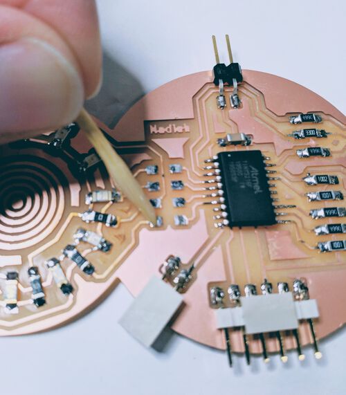
Usually I get all my components to solder at the start. However, with all the LEDs looking the same, I just grabbed each type of component at the time when I needed it.
As usual, I started with the central microcontroller, the ATtiny3216 in this case:
Everything went smoothly until I realized that I’d soldered the IR phototransistor the wrong way around (having looked at the mark of the IR LED right below it in my PCB layout instead). I desoldered it with the heat gun. However while trying to solder it on the correct way, I just couldn’t level out the phototransistor due to the pile of solder that was still present on both pads (ー_ー﹡; ) The excess along the GND pad didn’t want to go into the soldering wick, I think because heat could dissipate so quickly into the rest of the copper. After desoldering it again, and trying a few more times to remove the excess copper with the tip of the soldering iron I got the phototransistor on somewhat level again.
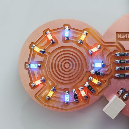
I left the ring of charlieplexed LEDs for last, not knowing exactly what colors to use. I eventually decided to go with blue, red and yellow/orange LEDs, going around a circle. Although each LED looked a little different, and not all were the same as the Digi-Key component that was in the Fab Inventory, at least it seems that it’s always the cathode side that is marked on top. Checking 5-6 times with my PCB layout that I’d oriented each LED in the correct way, I soldered on the 12 LEDs.
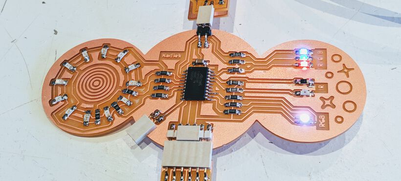
Too eager to test if the board worked I forgot to take a photo of it at the time (I did take the time to properly check the soldering with continuity tests on the multimeter though), but below is a photo of the board while I’d already replaced some of the resistors (and burned the lower-right side of the charlieplexed circle when I used the heat gun for too long).
Using the LEDs On My Board
I connected the board to my FTDI (for power) and UPDI (for programming), opened the Arduino IDE and wrote the short program below to turn on the separate red, green and blue LEDs:
//Turn on the R, G & B LEDs
#define PIN_LED_R 16
#define PIN_LED_G 0
#define PIN_LED_B 1

void setup() {
  pinMode(PIN_LED_R, OUTPUT);
  pinMode(PIN_LED_G, OUTPUT);
  pinMode(PIN_LED_B, OUTPUT);
}//void setup

void loop() {
  digitalWrite(PIN_LED_R, HIGH);
  digitalWrite(PIN_LED_G, HIGH);
  digitalWrite(PIN_LED_B, HIGH);
}//void loop
That worked, yay! I included the RGB LED in the same way, however when I uploaded the new program the LED stayed off. I then remembered that this RGB LED had a common anode and was connected to VCC, which would mean that I’d have to set the pins to LOW to turn them on (confusingly enough). A quick change to the code, setting all digitalWrite() of the RGB LED to LOW, and I was almost blinded by how bright the LED was (*≧▽≦)
I wanted to use PWM, with analogWrite, to dim the RGB LED so I could actually look at it. I then remembered that the green and blue pins of the RGB LED were connected to Digital only pins (according to the Arduino pinout). Would analogWrite even work?? But the pinout clearly showed those two pins as having PWM. Well, no harm in trying. And it worked thankfully. I did have to remember that in this case a value of 0 meant fully ON while 255 meant OFF.
//Dimming the RGB LED with PWM
//0 = full on, 255 = off
analogWrite(PIN_LED_RGB_R, 150);
analogWrite(PIN_LED_RGB_G, 150);
analogWrite(PIN_LED_RGB_B, 150);
I then tried to compare the colors of the R, G & B LED “pixel” and the RGB LED. Henk grabbed a small white acrylic sheet to place on top of the lights to better assess the combined value.
With the red, green, and blue LEDs fully on the center of the light I saw was indeed white. However, the sides were clearly very red and blue. The green LED seemed too weak when compared to the other two colors. I therefore wanted to replace the resistor of the green LED with a lower value. I’d already calculated that it should have at least 290Ω, not a big difference with the 499Ω that would remain on the red and blue LEDs sadly (the closest that the lab had was 330Ω), but something to try at least.
From the RGB LED I felt that the red color was perhaps too strong. However, I also felt that blue was also more powerful than green. Quite the opposite from what Neil did with his board, which had a lower resistor value for the blue LED. I therefore decided to only replace the resistor of the red LED from 499Ω to 1kΩ.
I’ve realized that my camera is unable to capture the colors that my eyes see, but just to give an impression of how it kind of looked when holding the white acrylic sheet over the LEDs

Having an idea of what I wanted to do with the “RGB” LEDs I moved on to the charlieplexing LEDs. I copied the code that decides what LED will be turned on from the tutorial that I’d used to create the schematic, updated to reflect the pins that I’d used:
/////////////// CHARLIEPLEXING ///////////////
#define PIN_CP_1 2
#define PIN_CP_2 3
#define PIN_CP_3 4
#define PIN_CP_4 5

#define PIN_CONFIG 0
#define PIN_STATE 1
#define LED_NUM 12

int matrix[LED_NUM][2][4] = {
  //           PIN_CONFIG                    PIN_STATE
  //    1       2       3      4         1     2    3    4
  { { OUTPUT, OUTPUT, INPUT, INPUT }, { HIGH, LOW, LOW, LOW } }, //LED no. 1
  { { OUTPUT, OUTPUT, INPUT, INPUT }, { LOW, HIGH, LOW, LOW } }, //2
  { { INPUT, OUTPUT, OUTPUT, INPUT }, { LOW, HIGH, LOW, LOW } }, //3
  { { INPUT, OUTPUT, OUTPUT, INPUT }, { LOW, LOW, HIGH, LOW } }, //4
  { { INPUT, INPUT, OUTPUT, OUTPUT }, { LOW, LOW, HIGH, LOW } }, //5
  { { INPUT, INPUT, OUTPUT, OUTPUT }, { LOW, LOW, LOW, HIGH } }, //6
  { { OUTPUT, INPUT, OUTPUT, INPUT }, { HIGH, LOW, LOW, LOW } }, //7
  { { OUTPUT, INPUT, OUTPUT, INPUT }, { LOW, LOW, HIGH, LOW } }, //8
  { { INPUT, OUTPUT, INPUT, OUTPUT }, { LOW, HIGH, LOW, LOW } }, //9
  { { INPUT, OUTPUT, INPUT, OUTPUT }, { LOW, LOW, LOW, HIGH } }, //10
  { { OUTPUT, INPUT, INPUT, OUTPUT }, { HIGH, LOW, LOW, LOW } }, //11
  { { OUTPUT, INPUT, INPUT, OUTPUT }, { LOW, LOW, LOW, HIGH } }  //12
};

void lightOn( int led ) {
  pinMode( PIN_CP_1, matrix[led][PIN_CONFIG][0] );
  pinMode( PIN_CP_2, matrix[led][PIN_CONFIG][1] );
  pinMode( PIN_CP_3, matrix[led][PIN_CONFIG][2] );
  pinMode( PIN_CP_4, matrix[led][PIN_CONFIG][3] );
  digitalWrite( PIN_CP_1, matrix[led][PIN_STATE][0] );
  digitalWrite( PIN_CP_2, matrix[led][PIN_STATE][1] );
  digitalWrite( PIN_CP_3, matrix[led][PIN_STATE][2] );
  digitalWrite( PIN_CP_4, matrix[led][PIN_STATE][3] );
}//void lightOn

void setup() {
}//void setup

void loop() {
  for(int l = 0; l < LED_NUM; l++) {
    lightOn(l);
    delay( 1000 / LED_NUM );
  }//for l
}//void loop
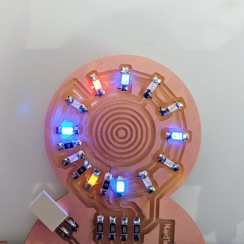
When I uploaded this code my LEDs turned on, on after another! That was a good first step. However, the order in which they turned on wasn’t along the circle. I therefore figured out which row in the matrix variable corresponded to which LED and adjusted the order of the rows to reflect my circle, resulting in a true “going around a circle” effect I was hoping for:
You can generally only turn one LED on at a time with charlieplexing. However, these LEDs can be turned on one after another much faster than our eyes can notice. It’s therefore possible to make it seem as if multiply LEDs are on at the same time by switching between LEDs really fast. The most simple case is to simply severely reduce the delay from the previous snippet of code. This will loop through all 12 LEDs so fast that they appear to all be on at the same time.
//Visually turn all LEDs on
void allLightOn() {
  for(int l = 0; l < LED_NUM; l++) {
    lightOn(l);
    delay(1)
  }//for l
}//void allLightOn
If the delay is too long you’ll see the LEDs flicker, if there’s no delay the LEDs seem rather dim. But with a tiny delay, all LEDs seemed on continuously except for one blue lED (LED no. 7) where I could notice a slight flicker.
Next, I wanted to (seemingly) turn on all the four blue LEDs for a while, then the four orange LEDs, then the red LEDs, going around in a circle. I started with trying to make it work for the blue LEDs, calling the lightOn function only for those four lights:
int group = 0;
lightOn(group);
lightOn(group + 3);
lightOn(group + 6);
lightOn(group + 9);
However that turned on a red and yellow LED as well?!
Only then did I finally look deeper into charlieplexing and how it truly worked in terms of programming and the pinMode and digitalWrite values. I checked out my schematic to see what should theoretically happen to turn on LED 1
- CHARLIE_1 should be the 5V source of the flow
- CHARLIE_2 should be the GND of the flow
- CHARLIE_3 and CHARLIE_4 should be off
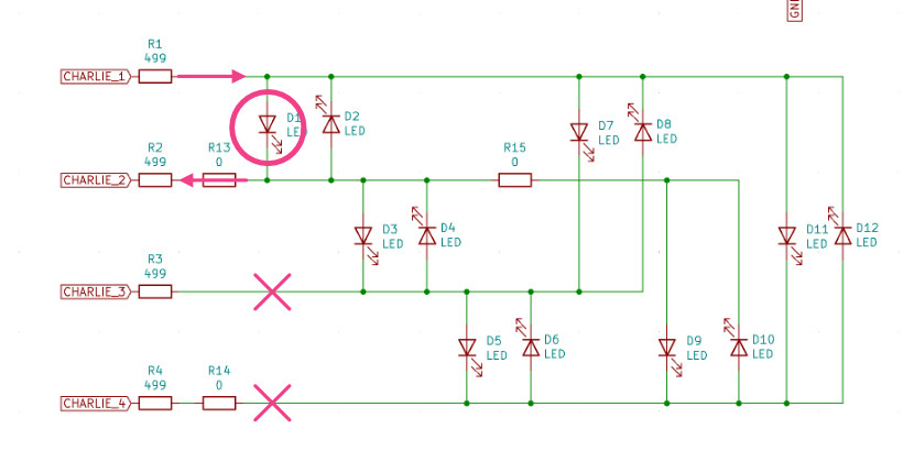
However, I didn’t quite know that that meant for the actual settings of the pins. Thankfully, the tutorial that I’d used for my schematic was actually pretty good at explaining: “To turn on led 1, there needs to be a HIGH signal on pin 1 and a LOW signal on pin 2, and pin 3 and 4 needs to be disconnected." which translated to the following settings:
- A pin that should be the 5V needs to have
pinMode(OUTPUT)and adigitalWrite(HIGH) - A pin that should be the GND needs to have
pinMode(OUTPUT)and adigitalWrite(LOW) - A pin that should be disconnected needs to have a
pinMode(INPUT)and adigitalWrite(LOW)
Thus, turning on LED 1 means to set:
//Turn on LED 1
pinMode( PIN_1, OUTPUT);
pinMode( PIN_2, OUTPUT);
pinMode( PIN_3, INPUT);
pinMode( PIN_4, INPUT);
digitalWrite( PIN_1, HIGH);
digitalWrite( PIN_2, LOW);
digitalWrite( PIN_3, LOW);
digitalWrite( PIN_4, LOW);
In general, to turn on any of the 12 LEDs only one pin will be set to HIGH, with the other three pins at LOW.
Checking out my code again, I thought that the code snippet was correct. However, perhaps I should add a little delay between them? And yup, that was the answer (*^▽^*)ゞ . Well, those two other LEDs were still sort-of on, but so dimly lit that it wasn’t really noticeable.
I then tried to think how I could switch between colors. Just looping through the three groups wouldn’t work, because the looping would go so fast that the lights would seem to flash. Instead, I needed to make the blue LEDs flash for X milliseconds first, then the red LEDs for X milliseconds and finally the yellow ones; a loop wrapped around the “four lights turned on” loop. This turned into the following code:
//Turn on all LEDs of the same color group
//time_on defines how long the group/color will be on
void crossLight(int group, int time_on = 500, int del = 3) {
  int num_loops = time_on/(del*4);

  for(int i = 0; i < num_loops; i++) {
    lightOn(group);
    delay(del);
    lightOn(group + 3);
    delay(del);
    lightOn(group + 6);
    delay(del);
    lightOn(group + 9);
    delay(del);
  }//for i
}//void crossLight

void loop() {
  //Make all blue LEDs turn on (seemingly)
  //and then all the red ones and then the yellow ones
  crossLight(0); //blue
  crossLight(1); //red
  crossLight(2); //yellow
}//void loop
Which looks as follows:
I found that the charlieplexed LEDs could be brighter still, so I also decided to change the resistors on each of the four charlieplexed pins to lower values. I saw that the red LED required the largest minimal resistor value with an Vf of 1.8V and If of 10mA, therefore needing a resistor of (5 - 1.8)/0.01 = 320Ω.
Now that I had a grasp of the charlieplexing I wanted to check out the infrared part of my board. I wrote the following program to turn on the IR LED and have the phototransistor capture the value:
#define PIN_LED_IR 14
#define PIN_PHOTO_IR 15
int value_ir = 0;

void setup() {
  Serial.begin(9600);

  pinMode(PIN_PHOTO_IR, INPUT);
  pinMode(PIN_LED_IR, OUTPUT);
  //Turn on the IR LED
  digitalWrite(PIN_LED_IR, HIGH);
}//void setup

////////////////////////////////////
/////////////// LOOP ///////////////
////////////////////////////////////

void loop() {
  value_ir = analogRead(PIN_PHOTO_IR);
  Serial.println(value_ir);

  delay(50);
}//void loop
It’s pretty darn difficult to see if an IR LED is on, especially if there are 6 bright LEDs right next to it. I therefore turned the other LEDs off, grabbed a toilet paper roll to make it dark around the IR LED, and then I noticed a slight deep red color coming from the IR LED. Great, so it was on!
However, I wasn’t really sure if the IR light was being reflected well into the phototransistor. Because the values that the phototransistor was returning was about 710 and went to 740 when I waved my hand over it, but dropped down to 50 - 300 when I moved my hand in really close or shined a flashlight onto it.
I added some code that takes a base_value during setup() and then compares against that during the loop() to decide which charlieplexing routine to show. However, I noticed that all the delay() calls in the charlieplexing routines made the program react too slow; the sensor was only capturing a value once every 1 second, so sometimes it wouldn’t capture a hand moving over it.
I therefore figured out how to rewrite my two charlieplexing routines to work without delay() calls instead; using a time to compare against and seeing if enough time has passed. Below is the new function for the lights going around a circle. The one for the “four LEDs of one color at once” is a little more complex, but I’ve added the code to the bottom of this documentation.
//Make the charlieplexed pin go around a circle
//not using a "delay()"

//Global variables
unsigned long previousMillis = 0;
//Keeps track of which LED is on during the roundCircleLight function
byte round_led_num = 0;

void roundCircleLight() {
    unsigned long currentMillis = millis();
    //Check if enough time has passed since the previous time
    if (currentMillis - previousMillis >= 1000 / LED_NUM) {
      previousMillis = currentMillis;
      lightOn(round_led_num);
      round_led_num = (round_led_num + 1) % LED_NUM; //cycle through NUM_LEDs
    }//if
}//void roundCircleLight
I was curious how things would change if I went from a 1kΩ resistor with the IR LED to a 330Ω one though.
Switching Resistors
Having now played with the four parts of my board (not the NeoPixel connection yet) I went back to the soldering station to desolder some resistors and replace them different values. I used the heat gun as before. I sadly made the mistake to try and desolder the four resistors along the charlieplexing side one after another, not giving the board the time to cool off in between. I noticed too late that I was overheating my board! I dropped the board and one of my LEDs along the lower-right quadrant shifted, due to the solder becoming too soft o(╥﹏╥)o . The board also discolored along that area of the board, turning brown, oops!
Thankfully, after fixing the LED and soldering on the new resistors all the electronics still worked ( ^∇^)
For the resoldering of the resistors fellow student Phil thought me a magical way to make the whole process so much better! To get rid of the extra solder that remains on the pads after removing the previous components with the heat gun, I should apply just a bit of flux onto both pads. If I then press the soldering wick onto the pad, with the soldering iron’s tip on top of it, the solder is just sucked away into the soldering wick in no time! It leaves a nicely flat pad to use again (•̀ᴗ•́)و
Phil said that I could also use it to solder on any component, tipping the metal pins/sides of a component with a little flux, then touching the pins with the soldering iron, which will add a bit of solder to them. For the resoldering, where there was still a little bit of solder left on the pads I would then only need to place the new resistor onto the pad and hold the soldering iron tip to the pad to completely fix it in place, awesome!

This really made a world of difference compared to how much trouble resoldering that phototransistor had been before. It was now quite straightforward to replace 7 resistors.
With the new resistors the charlieplexed LEDs were a little brighter, so that was nice.
The green LED of the R, G & B LED “pixel” was also brighter, but it still felt overpowered by the red and blue one. Well, I hadn’t attached these LEDs to PWM pins for nothing, so I just decided to dim the red and blue LED using software instead of hardware:
//Trying to create a balanced red, green and blue LED using PWM
//by dimming one color more than another
analogWrite(PIN_LED_R, 50);
analogWrite(PIN_LED_G, 255);
analogWrite(PIN_LED_B, 100);
I could not find a combination that would make the red and blue outer sides go away, however the above combination did make the central part of the light appear white (the red thus needed to be dimmed a lot).
The IR phototransistor was now giving off values around 350 instead of 710, so the IR LED was definitely shining a lot brighter. However, there didn’t seem to be any effect on the difference in values between the base and waving your hand over it state than when I’d used a higher value resistor.
An rgb LED With a Missing PWM Pin
For the RGB LED I wanted to investigate if I could move between colors. From my background in working with data visualization I already knew that changing between colors is best done within a different color space than RGB, but that moving between colors in the HSL or HSV color space is better.
Working with the NeoPixels before, I’d seen that it included a HSVtoRGB() function (H = Hue, S = Saturation, V = Value/Brightness), which seemed like a good place to start. Going with full saturation and brightness, I wrote a simple loop to go through all the hue values (running from 0 to 360 degrees).
//Loop through all hues at full saturation and brightness
for(int hue = 0; hue < 360; hue++) {
   byte color[3] = {0, 0, 0};
   //Put an RGB value into the color array
   HSVtoRGB(color, hue, 255, 255);
   displayColor(color);
   delay(100);
}//for hue
When I uploaded the program to my board it seemed to work, but there was a rather obvious jump where the color stayed a light pink for a long time and then suddenly became completely red. There was also a similar jump going from green to blue.
I did quite a lot of tests, just showing one color at a time and trying different values, such as:
byte color[3] = {255, 0, 1};
displayColor(color);
After many tests I realized that the pin connected to the blue color doesn’t want to invoke PWM! ⊙0⊙
. The blue LED would be off when using analogWrite(PIN_LED_RGB_B, 255), but fully on when only one below that; analogWrite(PIN_LED_RGB_B, 254).
At first I thought that it was just completely not working for that blue pin. However, after even more tests, I discovered that the PWM on the blue pin would work if I never activated the PWM on the green pin. Perhaps there was only 1 (digital) PWM available that both pins have to share, but can’t turn on at the same time?
I asked Quentin Bolsee about this, and he pointed me to this page on the megaTinyCore website. He mentioned that perhaps the millis() function was taking up one of the PWM options? However, I’m not understanding enough of what that page says. From how I understand it, it should be able to do PWM on both pins plus millis(). Nevertheless, I never got it working on both pin (I also tried setting the millis() to a different clock, but nothing worked)
I eventually had to give in, I just didn’t know enough about microcontrollers and their internal clocks and such.
EDIT | After talking with Quentin, I made an issue on the megaTinyCore GitHub. SpenceKonde picked it up within a few hours, said there was indeed an error, and had it fixed in about 24 hours! ( ^∇^) It would be included in the next release, which was too late for this week.
I therefore had to use Software PWM on the blue LED instead. I started by writing a simple version that uses delay():
void softwarePWM(int led_pin, float brightness = 0.1, float hz = 50) {
  digitalWrite(led_pin, LOW);
  delay((1000./hz) * brightness);  // ON for this long
  digitalWrite(led_pin, HIGH);
  delay((1000./hz) * (1 - brightness)); // OFF for this long
}//void softwarePWM
However, I saw that these delay() calls messed with the appearance of my charlieplexed LEDs, making them flicker. I therefore figured out how to rewrite it to using no delay() at all:
//A "no-delay" software PWM specifically for the blue LED
unsigned long previousMillisB = 0;
bool rgb_b_state = false;

void softwarePWM(int led_pin, float brightness = 0.1, float hz = 50) {
  unsigned long currentMillis = millis();

  if(rgb_b_state == false) {
    if (currentMillis - previousMillisB >= (1000./hz) * brightness) {
      previousMillisB = currentMillis;
      rgb_b_state = true;
      digitalWrite(led_pin, HIGH);
    }//if
  } else {
    if (currentMillis - previousMillisB >= (1000./hz) * (1 - brightness)) {
      previousMillisB = currentMillis;
      rgb_b_state = false;
      digitalWrite(led_pin, LOW);
    }//if
  }//else
}//void softwarePWM
With that code I adjusted my displayColor function to
void displayColor(byte color[]) {
  analogWrite(PIN_LED_RGB_R, map(color[0], 0, 255, 255, 0));
  analogWrite(PIN_LED_RGB_G, map(color[1], 0, 255, 255, 0));

  if(color[2] == 0) digitalWrite(PIN_LED_RGB_B, HIGH); //OFF
  else if(color[2] == 255) digitalWrite(PIN_LED_RGB_B, LOW); //ON
  else softwarePWM(PIN_LED_RGB_B, color[2]/255., 100);
}//void displayColor
And finally I had a properly changing RGB LED, with a slight flicker when the brightness of the blue LED is very low though (the video doesn’t capture the colors nearly as nicely as I can see with my eyes btw).
Note | My Arduino IDE 1.8.3 had always been buggy. Often freezing up if I had more than 1 sketch open. This week I’d had enough and decided to install the Arduino IDE 2-beta. It thankfully kept all of the boards and libraries that I had installed. However, I first had issues with it not being able to program my ATTtiny3216. I got the error “Upload error: Error: 2 UNKNOWN: a programmer is required to upload for this board”. A quick online search later and I found the solution. I have to go to Sketch -> Upload Using Programmer, or ⌘+SHFT+U, to run a program with the Arduino IDE 2, instead of the default uploading option. Not ideal, but I’ll take it if it means the program won’t continuously crash on me.
Combining it all, I adjusted the code to make my board “go crazy with lights” when you wave your hand near it (using the IR phototransistor)
Again, crappy video, but here it is, with my hand waving to the right of it outside of the screen every now and then.
Creating My NeoPixel Grid
For my final project I needed a grid with LEDs that I could control separately. To do this, NeoPixels seemed like a great approach. These are RGB LEDs where each “pixel” has its own driver chip to control its color and brightness (with PWM). They therefore only require one data line connection to a microcontroller to be able to control meters long of NeoPixels (your microcontroller does need to have enough SRAM to hold each information for each pixel though, needing 3 bytes per pixel). Furthermore, you can cut a strip of NeoPixels after each pixel, making it possible to create intricate grids of pixels.
I believe the NeoPixels were created by Adafruit, and there are several types; some being pure RGB, such as the WS2812, while others also include white, such as the SK6812. There is an Uberguide to NeoPixels on the Adafruit website, where the Best Practices is a must read before you truly start (which…. I didn’t do before I started I have to admit). The most important things for my final project (I think) are:
- Add a 1000μF, 6.3 V or higher capacitor to the 5V and GND of the power supply terminals to prevent the initial onrush of current from damaging the pixels.
- Add a 300 - 500Ω resistor between the microcontroller’s data output pin and the input of the first NeoPixel. The resistor should be at the end of the wire closest to the NeoPixel(s), not the microcontroller.
- NeoPixels powered by 5V require a 5V data signal.
- If your microcontroller and NeoPixels are powered from two different sources, there must be a ground connection between the two.
The Powering NeoPixels page goes further into the power consumption of (a large number of) NeoPixels, that you should distribute the power along a longer strip of NeoPixels to counteract the voltage drop, those kinds of things. Each NeoPixel can use 60mA (-> 0.3W with 5V), however, the page mentions that using 20mA on average is a good estimate for the actual amperage that is used across multiple NeoPixels, since generally, when mixing colors, the current drawn will be much less than a full-on white case.
The Puzzle Base
Before I could create a grid of NeoPixels I first had to decide how big my puzzle should be in the first place. Using a ruler I figured that an overall size of about 40 - 50cm for the full box might be interesting. However, to get a true sense of it, I had to see it at that size. I therefore opened Fusion 360 and drew a circle of 45cm in diameter, with a hexagon in the center, representing the puzzle area, of 30cm in diameter.
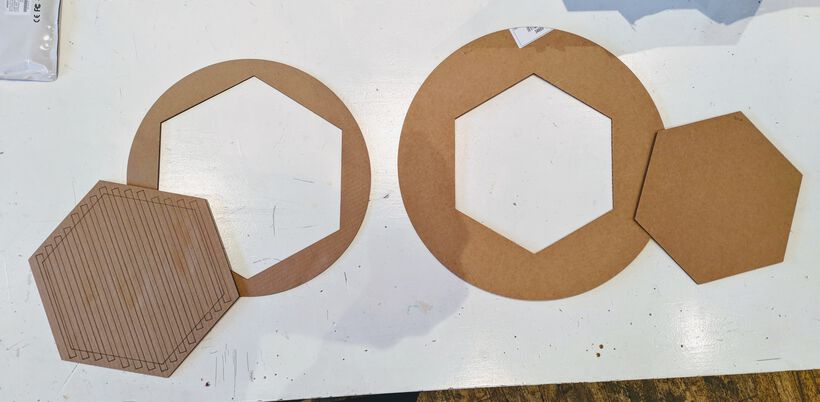
I then had this cut out of cardboard with the laser cutter. You can’t quite capture how big that size feels from just a photo (even if I place a pen for scale). However, it was pretty clear to me that this was too large.

The hexagon size wasn’t that bad, but the circle around it was too large. I didn’t really want to make the puzzle area smaller and therefore decided that I’d no longer include any “cubby holes” along the sides to store the puzzle pieces in.
I adjusted the circle and hexagon in Fusion, downsizing the circle to 38cm in diameter and the hexagon to 28cm in diameter (along the outside). I also added a few strips of 10mm wide to represent possible NeoPixel strips being laid next to each other. I added a second hexagon that was offset from the inner one that would represent the larger hexagon on which the NeoPixel strips would rest (this plateau being a bit larger than the actual puzzle area).
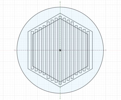

That resulted in a much better size, one that I felt could work. Below you can see the two versions side by side, with the larger version to the right
During the evening I took the time to properly calculate how the grid of NeoPixels should look. I wanted to lay out the grid as a hexagonal grid. Not only because of my love for hexagons (“hexagons are the bestagons”), but because it made more sense than a square grid; with a hexagonal grid each NeoPixel will be exactly the same distance from all six of its neighbors. It therefore has the most even spreading of the light.
I went to the “guide of hexagon coordinates” to help me with my math. I basically had two options for the grid: make them “pointy topped” or “flat topped” oriented. There was one element that basically fixed all the other values such as distance required between the strips; the distance between two NeoPixels along a strip. That was the one thing that I couldn’t change. I could either set this distance to represent the distance between two rows in the “pointy topped” version or the distance in the “flat topped” version.
With 60 LEDs per meter, that means that two NeoPixels are 1000/60 = 16.67mm apart. If I assume this represents a “pointy topped” version, that would imply that each hexagon “cell” has an outer radius of (1000/60) / 3 = 5.56mm (the distance between two rows of hexagons laying in the same row in the “pointy topped” version equates to 3 * R). This would mean that the distance between the center of two NeoPixel strips would only be sqrt(3) * 5.56/2 = 4.8mm. This wouldn’t even be possible since the strips themselves are 10mm in width.
For the “flat topped” version the outer radius comes down to a much bigger (1000/60) / sqrt(3) = 9.62mm (the distance between two rows of hexagons equates toR * sqrt(3)). This would make the distance between the center of two NeoPixel strips R * 1.5 = 9.62 * 1.5 = 14.43mm. That was a number that could work, and also leave 4.43mm in between each strip of NeoPixels in which I could cut out holes for the wires to run by that would go to the acrylic layer on top of the NeoPixel grid, which detect if a puzzle piece is placed.

Knowing the math and sizes it still took some time to create all strips in Fusion 360. I added little squares to represent the NeoPixels themselves, to help me assess the density (I used a simple Rectangular Grid option from one central square).
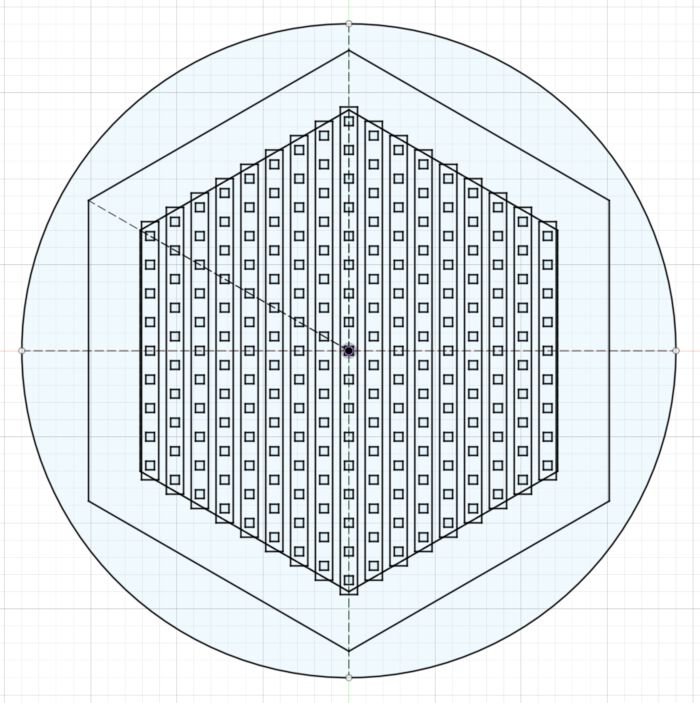

The grid looked good, with all the little rectangles being evenly spread out (^▽^) . Now that I had the grid I calculated how many NeoPixels this was. A hundred maybe, maybe a little more?
But no, this grid, laid out in a hexagon that measures only 28cm along its longest side contains 217 NeoPixels!! ✖‿✖
Damn, that was a lot! That would be 3.6 meters in length, and could (potentially) draw 0.06 * 217 = 13A of current. That… would be troublesome, but only in that I’d need a bigger power adapter than the 8A that I had. I did expect that I’d never turn such a dense grid on at full power, so perhaps I could work with the 8A power adapter, but that would be something to figure out later when I actually created the grid.
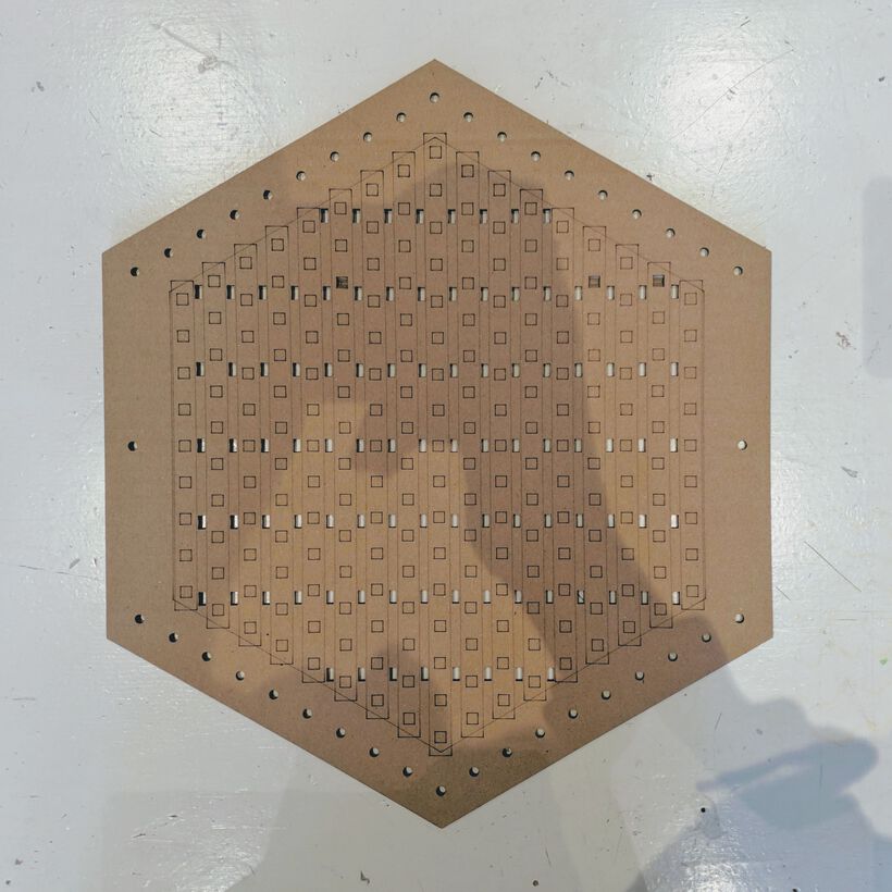
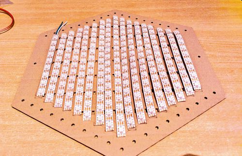
I saved this in two layers; one to be etched into cardboard and the other to be cut out. The result seemed like exactly the thing I needed to help me cut up the NeoPixel strip into smaller sections and solder parts back together in this grid configuration.
I took the cardboard example home for the weekend to perhaps make a start on the actual grid of NeoPixel strips. However, I decided that it would probably be smart to start with the wire cutting, stripping and soldering of the strips into a grid when I could stick them to the final hexagon, not the cardboard prototype.
I did rethink some of the holes on the prototype, feeling that I’d want the “main veins” of the 5V and GND to lie on top of the plate, not hanging below it. I’d then use some tie-wraps to hold the two main veins in place.
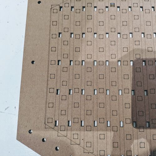
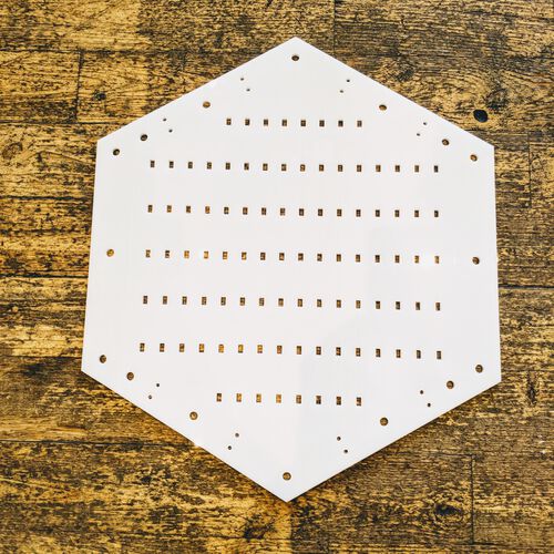
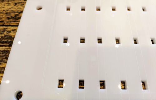
Back in the lab on Monday I got a nice 4mm thick white plate of acrylic that just fitted my hexagon. I started with a tiny rectangle test to see if I got the speed and power settings correct for it. When that turned out fine I etched the lines for the NeoPixel strips into the acrylic (to help me place them later) and cut out the holes and hexagon.
I made the etching very subtle with a speed of 100 / max power of 15% and min power at 10%. For the cutting I used a speed of 25 / max power of 100% and min power to 15%. I’d thankfully added a tiny rectangle test to the lower right of the hexagon, which showed me that the cutting hadn’t fully gone through along the bottom-right half (darn laser cutter really needs to be tuned). Redoing parts for a second try with the same settings and it all cut through (without any burn marks on the bottom even).
Soldering The NeoPixel Grid
Before I did anything to the actual 5m NeoPixel strip, I first tried to find some online sources that showed how to solder separate strips together. Specifically when they had the waterproof coating. Thankfully, I found a really handy video that shows the entire process. This explanation of a NeoPixel based clock also helped with understanding how I’d want to run the wires.
With the cardboard prototype (on which the etchings are much easier to see), I started cutting the 5 meter long NeoPixel strip into section for my grid with a sharp scissors.
I gently peeled up the first ±5mm of the waterproof coating, which went reasonably easy, and cut it off with a scissors to expose the 5V, data and GND copper pads.
With these strips it’s very important to always connecting the DOUT (data out) of a strip to a DIN (data in) of the next strip. I therefore had to be very precise in the order in which I placed each strip.
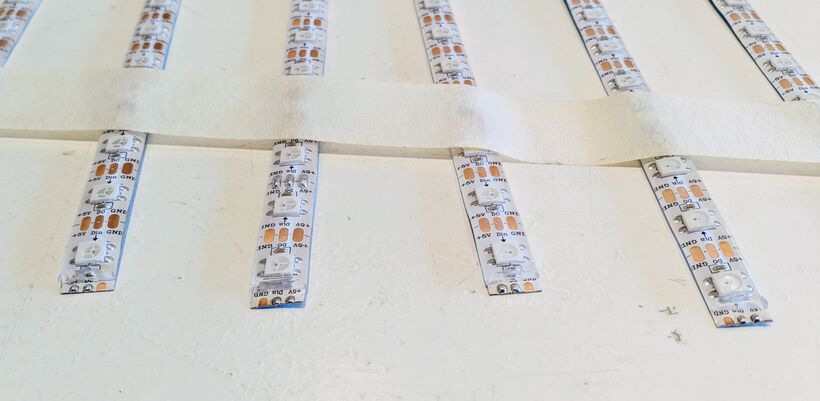
After placing the strips on a table, I taped the ends to it, to keep them in place for me to add solder to the copper pads on the ends of each strip.
Because I was going to feed in the 5V from above and connecting all the GND at the bottom, I only needed to solder 2 out of the 3 pads on each side (I always had to solder the DIN/DOUT pad).
The pads didn’t want to take the solder easily, most stayed on the soldering iron, but when a bit of solder finally landed on a pad, they formed nice tiny hills.
With the pads soldered, I started cutting strips of wire to solder to these pads. My partner had given me some wire that would be big enough to potentially handle 1A at 5V.
I generally cut off a section of about 5cm, red for 5V, black for GND and yellow for the DATA (I didn’t have green). Using a wire stripper I cut of a tiny section from one side, to connect to the strip, and a much larger section from the other side, to connect to the “main vein” for the 5V and GND wires
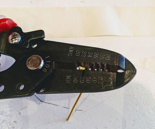
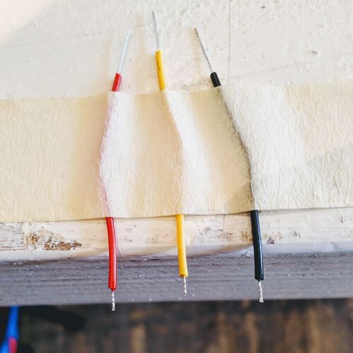
(Nevermind the tape in the image above-right. I first tried to solder the tips of the wires before I placed them on the copper pads, but soon found out that they didn’t want to take solder easily, that I was more likely to melt the isolation, and that it really made no difference when getting them to stick to the NeoPixel pads)
Adding a bit of solder to my iron, I would then place the tip on the top of the little blob on the NeoPixel pad, wait a second for it all to melt, and then slide in the wire from below.
If I actually managed to make it go like that, it resulted in a beautiful connection. However, the wires weren’t always cooperating, and bended or moved in strange ways as I tried to move it in. Nevertheless, after 2-3 hours of work I had a board with all wires soldered to it!
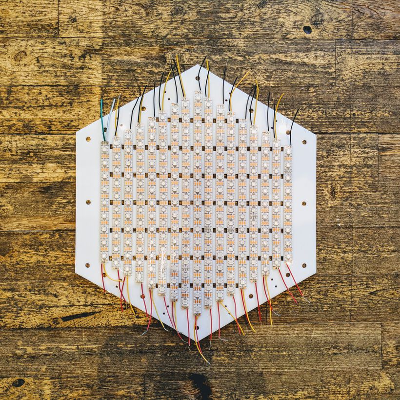
I’d stuck the strips to the acrylic sheet to continue to the harder parts; soldering the other ends of each wire.
I started with the yellow wires, which needed to be looped back onto the wire next to it, to pass on the DATA. I always had to recut and restrip the yellow wires because I’d left them too long.
Using tweezers I could keep the end in place as I heated up the solder on the copper pads, but it was definitely more difficult to properly solder the other ends of the yellow wires.
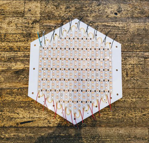
Now came the most difficult part of all, connecting all the 5V and all the GND lines to a “main vein” along the top and bottom.
During the weekend my partner had given me two sections of some really thick wire, since these “veins” should potentially be able to carry 13A. We’d already tried to strip some of the isolation away at different sections, to which I could then tie and solder 2-3 of the wires coming from the NeoPixel strips.
This was by far the most slow going process, having to cut basically each wire, stripping it quite exactly so it would align with one of the naked sections of the vein, winding the 2-3 wires coming from the NeoPixel strips together and then carefully wrapping it around the vein, applying a generous amount of solder onto it and finally adding a (5mm) shrink tube around it for protection (and heating it with a heat gun while trying to protect the acrylic plate and NeoPixel strips).
Throughout the process I kept on checking all the 5V and GND connections of the NeoPixel strips and seeing that they connected to the main vein using a multimeter.
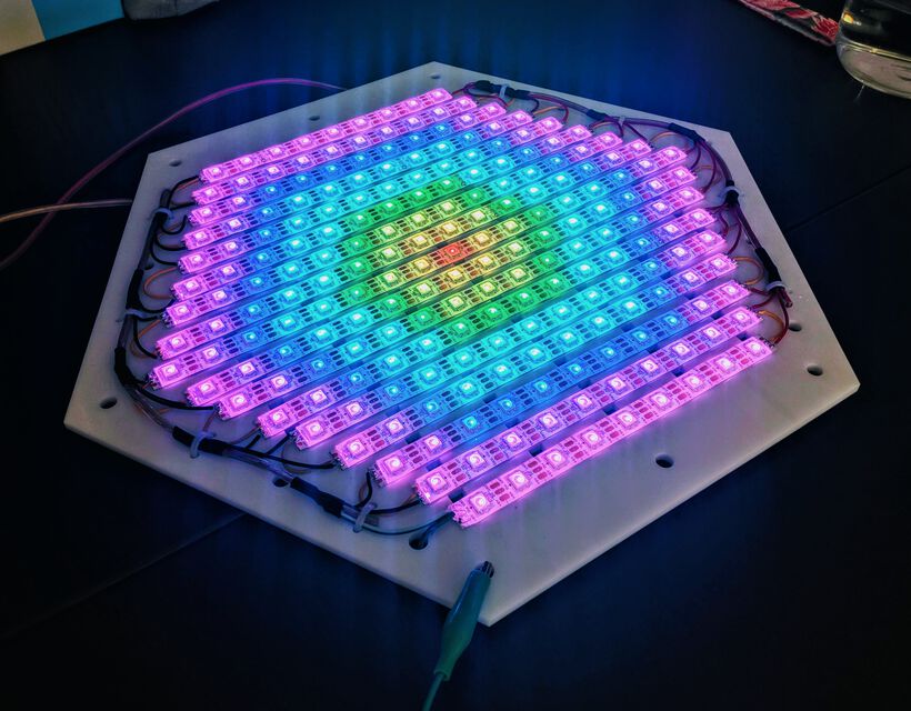
About 3 hours later again, and I had connected everything! (^ᗨ^)

All-in-all this took about 8 hours. Below a tiny animation to show the full buildup in only a few seconds:
Testing the Grid
Now came the most nerveracking moment; would the NeoPixels still work? This thought had been haunting me all day. I had been working for 8 hours to cut up the strip and place it in this grid, just hoping that I didn’t make a mistake along the way, because I could only test it at the far end.
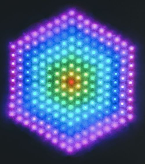
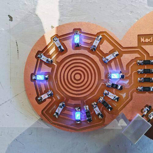
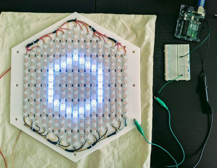
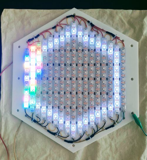
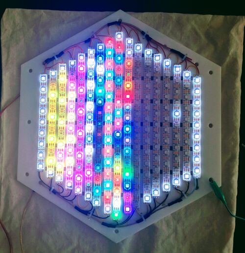
I grabbed my Arduino, 5V/8A power supply, giant capacitor, bread board with a resistor, wires, alligator clips, etc. and slowly connected everything. After uploading a change to the program for 217 NeoPixels, and very low brightness, and finally connecting to the adapter AND IT TURNED ON!!!! (๑•̀ㅂ•́)ง✧
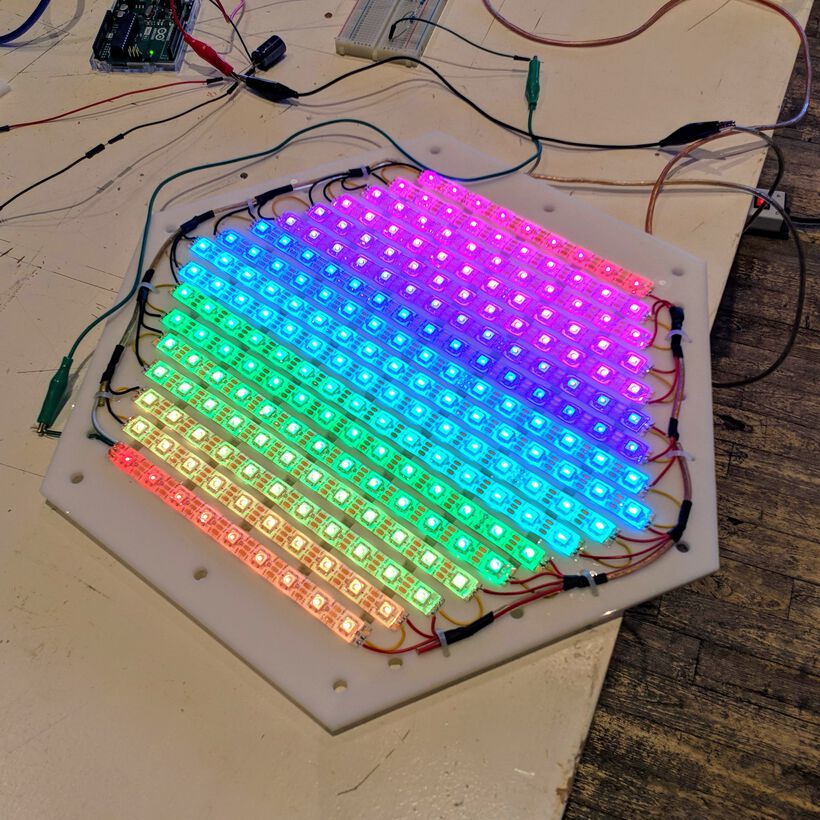
I had literally been shaking as I connected the NeoPixel grid from nervousness, so seeing the rainbow along all the strips made me beyond excited! And really lifted this anxiety that had build up inside of me.
It was the end of the day, so I carefully packaged it all up and took it home to do some more tests on the power consumption.
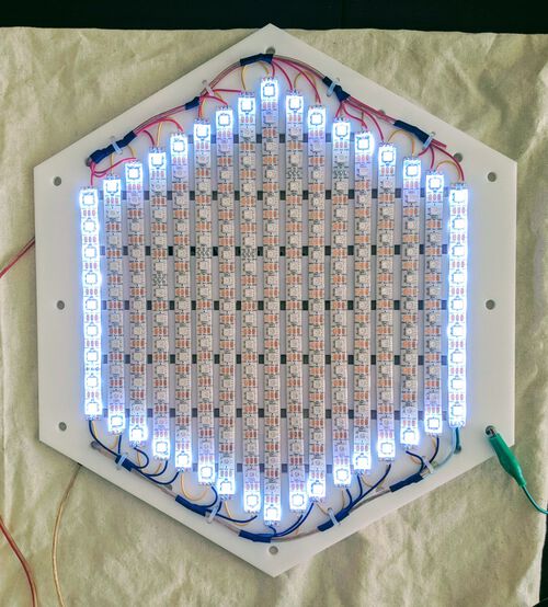
Connecting the grid to our lab power supply at home, I saw that the 217 NeoPixels were consuming 1.2A when in their rainbow mode and brightness set to 25%. When set to white, the current went up to 2.18A, which was still not the ±3.25A it could potentially get.
Using a multimeter I tested the voltage going through each strip itself, which was about 4.6V. This dropped to 4V when I set the brightness to 100% (while the current went to 6.75A). Thus even using thick wires, I was experiencing quite a voltage drop. Oh well, 100% brightness at 6.75A seemed like more than enough.
Programming the Grid
Up until now I’d been using my Arduino to program the grid with. I really had to test if it would work with my ATtiny board.
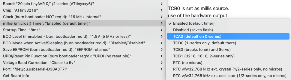
Compiling the same NeoPixel code, but for the ATtiny3216 board I got an error that said CPU SPEED NOT SUPPORTED. A quick online search showed me that the NeoPixels didn’t want to be run at the default 20Mhz of the board, but that I should use 16MHz instead. Thankfully, that was easy to adjust in the board settings:
![]()
And after that it worked!
![]()
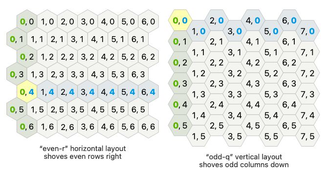
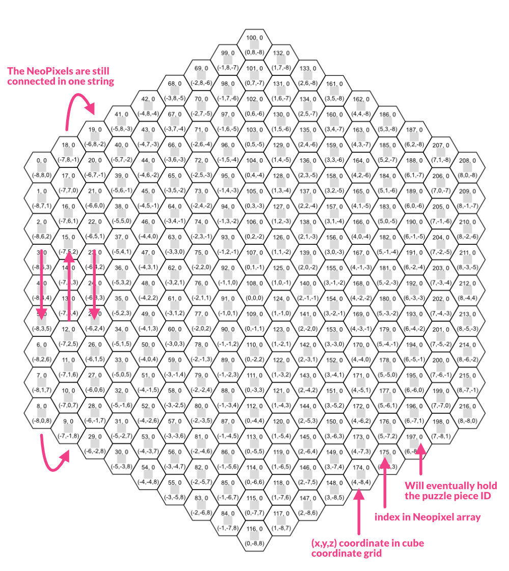
Now came the hard task of creating light patterns within this hexagonal grid, when the LEDs on the NeoPixel were all connected in one long string. I looked through the hexagon guide again and decided that going for the cube coordinate version would make most sense, and make calculations easiest.
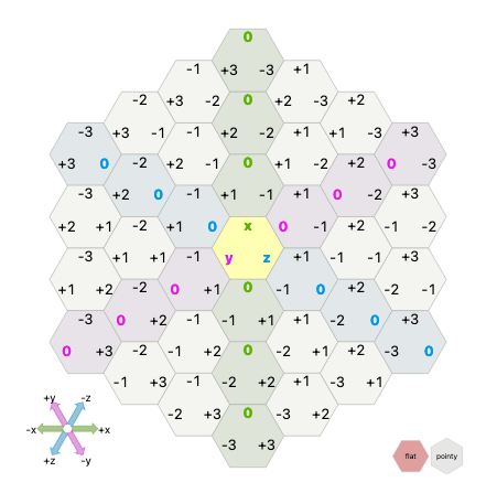
I recreated my hexagon grid in Affinity Designer and manually typed in the coordinates that I’d need to go from a string of pixels to a grid of pixels. For example, NeoPixel 163 would be grid coordinate (4,3,-7):
Once I had that, I created three variables in my Arduino script of 217 entries long, that contain the x, y & z coordinates.
#define ledCount 217;

int x_grid[ledCount] = {-8,-8,-8,-8,-8,-8,-8,-8,-8,-7,-7,-7,-7,-7,-7,...};
int y_grid[ledCount] = {8,7,6,5,4,3,2,1,0,-1,0,1,2,3,4,5,6,7,8,8,7,6,5,...};
int z_grid[ledCount] = {0,1,2,3,4,5,6,7,8,8,7,6,5,4,3,2,1,0,-1,-2,-1,0,...};
From that I could give a grid coordinate and get back the NeoPixel index for example:
int hexToIndex(int x, int y, int z) {
  //Not very efficient, but loop over all indices
  //and return when x, y and z are all correct
  for(int j = 0; j < ledCount; j++) {
    //Actually, you don't need to test z as well because x + y + z = 0
    if(x_grid[j] == x) and y_grid[j] == y) { //and z_grid[j] == z) {
      return j;
    }//if
  }//for j

  //if nothing found
  return -1;
}//hexToIndex
And I could then turn on every NeoPixel from a grid perspective:
  //Light up the central NeoPixel
  int index = hexToIndex(0, 0, 0);
  strip.setPixelColor(index, 255, 255, 255);
  strip.show();
For this week I wanted to try and program a “simple” color explosion in the grid. Where it starts at any random pixel in the grid and then “explodes” outward. On the hexagon guide there is thankfully some math and JavaScript code on how to calculate the cells that are in a “ring” that is X steps away from any hexagon cell. To help me figure out how this JavaScript example could be written in C I found this GitHub repo on hexagon coordinates and math. The code was way too complex though, so it took me quite some time to write my own simple version that can add the coordinates of two cells, to scale it, to find its neighbors, etc.
I really wish that you could return more than 1 value from a function, or to more easily replace values within a multi-dimensional array, or even to add onto an array. Not a fan of C at all… ( ̄ー ̄)
(during the regional review I got the tip to look into structures and learn about pointers (and to use * instead of [] in my function arguments.))
//The difference in x, y, z direction to the neighbors of any cell
const int hex_direction[6][3] = {
  {1, -1, 0},
  {1, 0, -1},
  {0, 1, -1},
  {-1, 1, 0},
  {-1, 0, 1},
  {0, -1, 1}
};

//Copy a certain direction into a new value
void hexDirection(int direction, int coord[]) {
  coord[0] = hex_direction[direction][0];
  coord[1] = hex_direction[direction][1];
  coord[2] = hex_direction[direction][2];
}//hexDirection

//Find the neighbor at a certain direction of one cell
void cubeNeighbor(int a[], int direction, int coord[]) {
  int cube_direction[3];
  hexDirection(direction, cube_direction);
  cubeAdd(a, cube_direction, coord);
}//cubeNeighbor

//Add the coordinates of two cells
void cubeAdd(int a[], int b[], int coord[]) {
  coord[0] = a[0] + b[0];
  coord[1] = a[1] + b[1];
  coord[2] = a[2] + b[2];
}//cubeAdd

//Scale the coordinates of one cell
void cubeScale(int a[], int f, int coord[]) {
  coord[0] = a[0] * f;
  coord[1] = a[1] * f;
  coord[2] = a[2] * f;
}//cubeScale
Which combined to the following code to get all the hexagon cells that are radius steps away from the cell given as center[]:
void cubeRing(int center[], int radius, int cube_all[][3]) {
  int cube_direction[3];
  hexDirection(4, cube_direction);

  int cube_scaled[3];
  cubeScale(cube_direction, radius, cube_scaled);

  int cube[3];
  cubeAdd(center, cube_scaled, cube);

  byte counter = 0;
  for(byte i = 0; i < 6; i++) {
    for (byte j = 0; j < radius; j++) {
      cube_all[counter][0] = cube[0];
      cube_all[counter][1] = cube[1];
      cube_all[counter][2] = cube[2];

      cubeNeighbor(cube, i, cube);
      counter++;
    }//for j
  }//for i
}//cubeRing
Eventually though I got it working an saw a tiny “ring” on my NeoPixel grid (ノ◕ヮ◕)ノ*:・゚✧
Note | Because the uploading went 3-4 times faster on my Arduino Uno than my own board with the ATtiny3216 I switched to using the Arduino to program the Neopixels.
I then updated the script to loop through different radii, to mimic a “light-explosion”. However, when the ring became bigger than a radius of 7, the final string of pixels did just whatever they wanted?! (●__●)
If I increased the ring to a radius that was even bigger, even more pixels went crazy (image below left). Eventually manually located the indices of the outermost ring of NeoPixels, which I hardcoded into an array and used this to light the NeoPixels with, and then it worked perfect (image below right). I had NO idea what was going on here??!!
This part really stumped me for a long time (as in several hours). Whatever I tried, it seemed that whatever my cubeRing function returned was exactly the same as the hardcoded array; I compared variable types (both were int), I tried overwriting the hardcoded array with the cubeRing values, but it didn’t work. I refactored some functions to pull even more steps apart; to create a new array with the indices that came from running the grid cells of the cubeRing function through the hexToIndex function, and only then using it to set the NeoPixels. But nothing that I tried worked.
I couldn’t find anything about this when I searched online, but I think it was also partly due to me not using the right words to look for, having no clue as to what was going on in the first place.
And then finally during the weekly local review, fellow student (and extremely smart electronics expert) Erwin asked if it was perhaps due to the dynamic memory overflowing, because it only affected the end of the NeoPixel string, that the program was trying to address “memory” after the official dynamic memory (the SRAM I believe), which would result in nonsense values. He asked what microcontroller I was using.
Hmmmmm, if it was the microcontroller, I figured I could try using my ATtiny3216 board instead. I uploaded the NeoPixel program to it (which took forever sadly), and amazingly it worked fine! ( ^∇^)
I don’t understand the reason for it completely right now. Why it didn’t work on the Arduino Uno and did work on the ATtiny3216, both have 2048 bytes of SRAM memory. Could the ATtiny3216 be more efficient in how it handles int than the ATMega328 of the Arduino Uno?

Well, the week was beyond over by now, so I had to let this rest for now. It being my final project, I’ll be returning to fine-tuning the lights effects for hours and hours to come (*≧▽≦) Perhaps I’ll learn more about the dynamic memory and such along the way.
Bonus | A Table Light - Part 1
A few weeks ago I made a big ceiling light and I’m planning on hanging it over our dining table. Over the course of the past weeks me and my partner have been sanding each slice of the lamp by hand for a more refined result, and we’ve finally finished.
For the next step I bought an FOB / FCOB LED strip which has a very high density of LEDs to the point where you don’t really see the separate LEDs, which is something we very much wanted for this light.

The downside is that you can’t program this LED strip the same way as the NeoPixels, there’s only a 12V and GND connection. Thankfully, the only thing I want this light to do is to turn on and off and change its brightness, the latter of which can be done via PWM. How exactly I didn’t know yet.
My ultimate goal was to be able to dim the LED strip using Google Assistant (voice control) and the Google Home that we have in our home (and via the Google Home app). I’d therefor bought an ESP32 Dev Board, since I’d used the ESP32 before, which has WiFi and it can do Hardware PWM (unlike the ESP8266 which only has Software PWM and thus could stutter if the WiFi is heavily used apparently).
While searching online for ways to connect an ESP32, running on 3.3V (and 5V was also possible for this dev board) to a 12V LED strip, I didn’t find a whole lot of examples sadly.
But through the 2-3 relevant sites I found, I did slowly build up a picture that I’d need a transistor for the PWM part. I hope I’m explaining things right, but an NPN transistor has three legs/pins:
- You connect one leg to a microcontroller pin, which is outputting a PWM signal at 5V (or 3.3V depending on the MC) and low current, in the mA range. This pin is called the base.
- Another pin is connected to the GND of the power supply, a 12V adapter in this case. This pin is the emitter.
- Finally, there’s the collector pin in the middle, which you connect to the GND of the 12V LED strip.
You’re basically breaking up the direct connection from the GND of the power supply to the GND of the LED strip by placing a NPN transistor in between (PNP transistors have to be connected on the other side).
You can use the transistor as a switch. By applying a (high enough) voltage from the microcontroller to the base, a current is allowed to flow from the collector to the emitter. It makes it possible to use a small voltage and current to control a larger voltage and current. The microcontroller will output a PWM on its pin, which will allow the circuit connected to 12V to go on and off at the same frequency, thereby effectively having PWM on the main circuit as well.
This video about transistors is quite good (I have to emit that the names emitter and collector still confuse me as what should be attached to it).
A second big aspect of this circuit would also be to power the ESP32 board with the 12V adapter. However, the dev board can only handle 5V max. This is where a voltage regulator comes into play.
It looks deceivingly similar to a transistor, also having three legs. In this case:
- There’s an INPUT pin which is connected to the input voltage of the power source, which would be 12V in my case.
- The middle pin, the GROUND, is connected to the ground of the power supply.
- The OUTPUT pin is connected to the microcontroller and delivers the voltage that it needs, 5V in my case.
The difference between the 12V and 5V is basically “dumped” into the ground pin and turned into heat. These voltage regulators can therefore get quite hot, depending on what input and output voltage you’re combining (the transistors can also get quite hot actually).
Figuring out the Circuit Diagram
How to combine these two components between my ESP32, power supply and LED strip was what I had to figure out. For that the circuit diagram in this video from Tech StudyCell became a major help for me (ignoring the potentiometer and tiny LED):
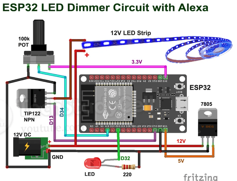
I have to admit that while I was first investigating this and trying to set-up my own version, I failed to grasp it. I gave up after 1-2 hours on Sunday evening, for it to somehow “click” enough for me on Monday morning in the Waag to actually implement it on my own.
My partner thankfully had some TIP122 transistors left from a small “patch-up” in the past, where apparently this component broke on a machine of his.
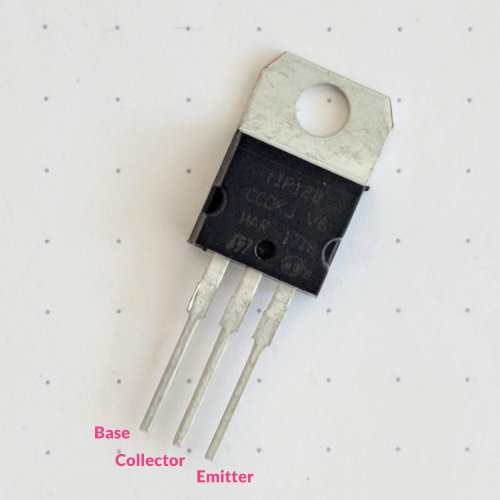
When looking at the datasheet of the TIP122, I saw that the collector-base voltage & collector-emitter voltage is 100V which seems rather overpowered for my 12V project.
The emitter-base voltage is 5V, perfect for the 5V pin on my ESP32 board. Finally, the collector current (dc) is 5A, enough for the ±1.25A that could run through my 1.5m long LED strip (it’s 10W per meter at 12V -> 10/12 * 1.5 = 1.25). The base current (dc) is 120mA, also good for a typical microcontroller.
I was so new that I really wasn’t sure if I’d interpreted this all correctly, but from what I could see, the TIP122 was overpowered for the project, but in terms of the base side, with the 5V and 120mA, a good match.
I’d only need the voltage regulator when I wanted to hook up the ESP32 board to the power supply as well. I could start out with it connected to my laptop and just get the circuit working with the transistor and the LED strip.
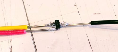
I started out simple by setting digitalWrite(HIGH) value on the pin that I’d connected to the transistor to see it the LED strip would turn on (there are also some wires in the image below to a test LED).
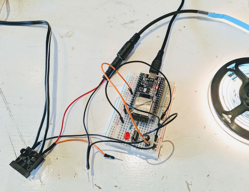
Which thankfully worked! I then wanted to test if I could run the ESP32 board via the 12V power supply as well.
At first Henk thought he didn’t have a 7508 voltage regulator in the lab, and advised me to take an SMD component that output 5V (I don’t know which one, because the version in the Fab Inventory is different), and soldered some wires to it so I could connect them to other wires / alligator clips.
I then applied a royal amount of hot glue onto the connection to prevent the soldered points from breaking.
Even more wires later, and it was also working while fully unplugged from my laptop!

I did feel the voltage regulator getting hot through the hotglue, so I unplugged it again, using my laptop to power the ESP32 board instead while I figured out how to do hardware PWM.
Hardware PWM on the ESP32
At first I was a bit overwhelmed when I opened up a few pages about the hardware PWM on the ESP32. The ESP32 seems to have its own code for setting it up, using functions that were completely new to me, and using jargon that I didn’t understand.
However, after finding a few really good tutorials, it was actually fairly easy thanks to the ESP32 Arduino library that wraps all the hard stuff up into a few very organized functions. I had installed this already to be able to use an ESP32 in previous weeks.
It could probably be made even easier if that library had made it so you could use analogWrite() to create hardware PWM, as is done with the megaTinyCore for ATtiny boards for example. But perhaps the ESP32 way gives you a little more tools to adjust the PWM signal?
In general, there are only three functions required to get PWM working:
ledcSetup(channel, frequency, resolution_in_bits)| The ESP32 has 16 channels on which it can create different PWM signals. These aren’t pins! You can assign the same PWM channel to any number of pins. With this first function you create a PWM channel, say channel 0. You set the frequency of that channel in Hz, and finally you say what duty resolution that timer can have, in bits. The duty cycle is the ratio of time a load or circuit is ON compared to the time the load or circuit is OFF. Setting the resolution to 10 means 10-bit resolution. There’s a trade-off between the frequency and the resolution: A PWM frequency of 5 kHz can have a maximum resolution of 13 bits, while a frequency of 20 MHz can have a maximum resolution of 2 bits.ledcAttachPin(LED_pin, channel)| Attach an actual GPIO pin of the ESP32 to the PWM channelledcWrite(channel, duty)| Writes out a duty cycle value to the specified channel. The duty cycle value should be between0 - 2^resolution.
I wrote the following program to implement the hardware PWM with the ESP32:
//Hardware PWM with an ESP32
#define LEDSTRIP_pin 13

/* Setting PWM Properties */
#define PWM_channel 0 //randomly chose channel 0
#define PWM_freq 40000 //40kHz - set high so I don't hear the buzz
#define PWM_resolution 10 //10-bit resolution

//The max duty cycle value based on PWM resolution
const int MAX_DUTY_CYCLE = (int)(pow(2, PWM_resolution) - 1);
int duty_cycle;

void setup() {
  //Setup timer
  ledcSetup(PWM_channel, PWM_freq, PWM_resolution);
  //Attach the PWM channel to the GPIO Pin
  ledcAttachPin(LEDSTRIP_pin, PWM_channel);
}//void setup

void loop() {
  /*Fading example*/
  //Increasing the LED brightness with PWM
  for(duty_cycle = 0; duty_cycle <= MAX_DUTY_CYCLE; duty_cycle++) {
    ledcWrite(PWM_channel, duty_cycle);
    delay(3);
  }//for
  //Decreasing the LED brightness with PWM
  for(duty_cycle = MAX_DUTY_CYCLE; duty_cycle >= 0; duty_cycle--) {
    ledcWrite(PWM_channel, duty_cycle);
    delay(3);
  }//for
}//void loop
Uploading it to the ESP32 dev board and my LED strip starting fading in and out (๑•̀ㅂ•́)ง✧ The first part of my end goal of my dining table light was working! Well, it was still using a breadboard and lots of wires, an overkill in an ESP32 dev board where I was only using 1 pin, and a tiny voltage regulator that got so hot that the hot glue melted around it again. But hey, it was a big step for me, working out the required hardware in particular!
During next week’s documentation I’ll explain how I went about the next step; being able to control the brightness via an app and voice control (⌐■_■)
Reflections
Thinking back on this busy and “all over the place” week it’s hard to think that only one week passed since the Output Devices week started (*^▽^*)ゞ
What went wrong
I tried to desolder all four resistors of my charlieplexing pins one after another. Sadly, this made the board itself overheat and one section of my Charlieplexing LEDs became quite dark, as if it had been burned. Thankfully the components all still worked afterwards.
Somehow I couldn’t get the PWM to work on both pins PC0 and PC1 at the same time and had to use software PWM for the blue pin instead.
I was stuck for quite a long time on the NeoPixels giving really odd results when I tried to create a ring of NeoPixels while using my Arduino Uno. In the end it was something that I’m completely unfamiliar with; the dynamic memory probably overflowing. Thankfully, the ATtiny3216 didn’t have this issue. But it’s good to know that this can happen in case I get strange NeoPixel behavior in the future. I hope I also learn more about writing more efficient code, so I don’t get any overflow at all.
What went well
No (real) issues with my board in terms of design, milling and (initial) soldering.
I’m happy to have learned what Charlieplexing is, and know how to program with it now!
I’m even more happy that the giant process of cutting up the 5 meter NeoPixel into strips, then soldering wires to them to connect all separate strips to each other and back to 5V and GND, taking 8 hours to complete, resulted in all of my NeoPixels still working ᕦ(ò_óˇ)ᕤ
What I would do differently
My separete red, green, and blue LEDs to give the impression of an “RGB” LED didn’t work that well. I think part of the issue is that I have only 1 “RGB pixel”, so the sides aren’t compensated. I think if I’d made a whole grid of these RGB pixels next to each other, then the central part could’ve been white, or set to any color. However, the outsides would always convey the LEDs that were placed there.
However, I could’ve also tried a different orientation for my “RGB pixel”, not placing them side by side, but in some different orientation (I’d search online to see if any particular orientation would be advised).
I need to remember to add a 470Ω resistor from the data line to the NeoPixel strip. I should also add a 1000μF capacitor between the 5V and GND wires of the power supply running to the NeoPixel strip to prevent the initial onrush of current from damaging the pixels. After the group assignment I made sure to use a breadboard to make sure there was a resistor between my microcontroller and the NeoPixels, and I added the capacitor to the power supply connections.
Wrapping up
Busy week! So many separate parts that I worked on, but I learned a lot in all kinds of areas: coding, soldering, working with wires, transistors, etc. I’m very happy that I got a good start on my final project as well with the NeoPixel grid (^ᗨ^)