
Characterize the design rules for your in-house PCB production process.
Send a PCB out to a board house.
Make and test the development board that you designed
to interact and communicate with an embedded microcontroller.
Extra credit: make it with another process.
Assignment Requirement
Status
Linked to the group assignment page
Completed
Documented how you made (mill, stuff, solder) the board
Completed
Documented that your board is functional
Completed
Explained any problems and how you fixed them
Completed
Uploaded your source code
Completed
Included a ‘hero shot’ of your board
Completed
For this assignment I milled, soldered and tested the microcontroller development board I designed in Week 6 Electronic Design.
To prepare the design for milling I used Carbide Create which is the software that converts the 2D design into G-Code. It can also prepare G-Code compatible with the Nomad 3 Desktop Milling Machine which is the machine I used for the PCB Milling.
I created two files in CorelDraw for this process, a .png for pocket or engraving and a .svg for the contour or cutting. I first used the Trace Image tool to import the .png image.
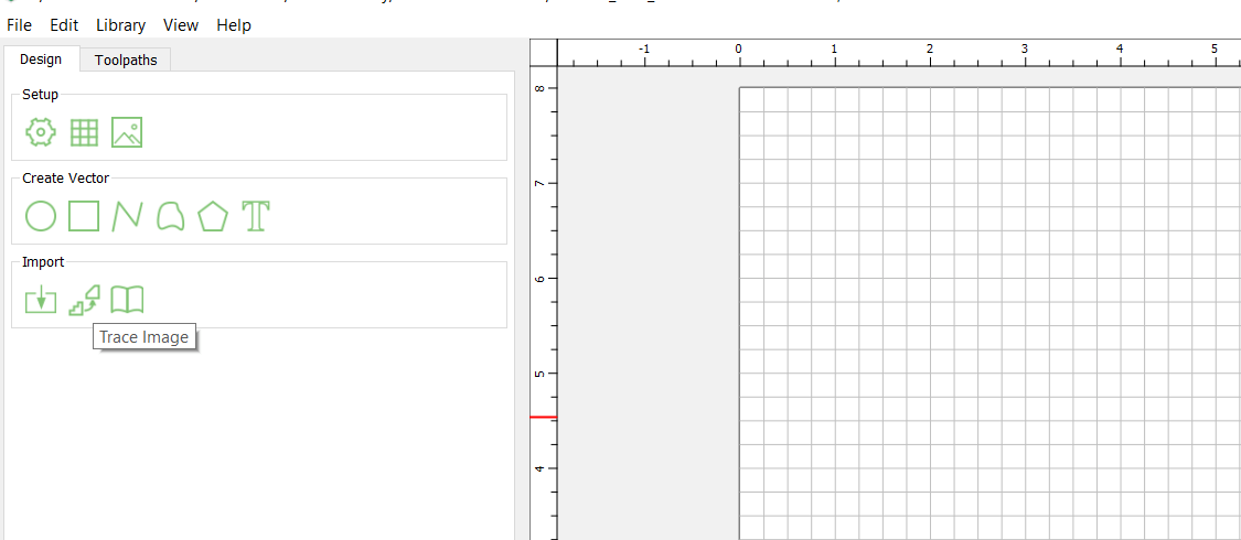
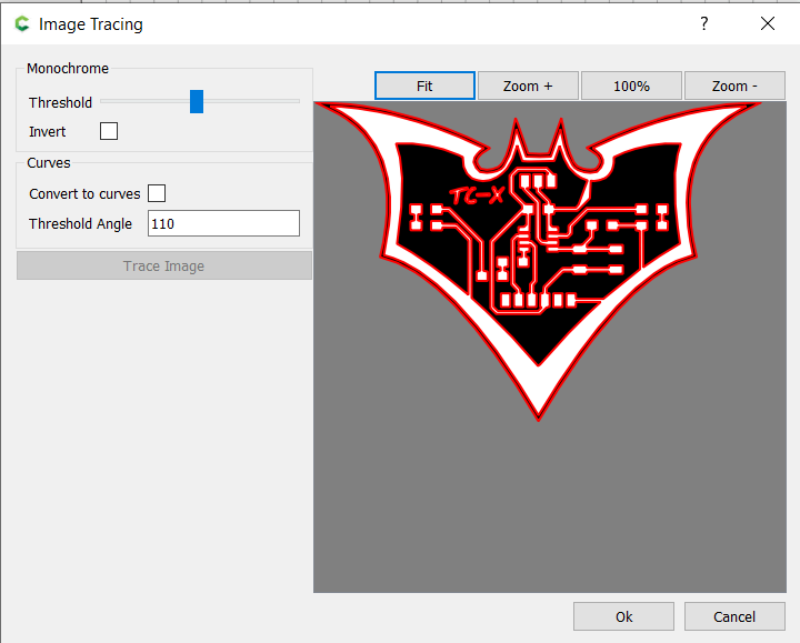
The Image Tracing window opened allowing me to set the Threshold and Threshold Angle and also Invert the image if necessary (switch areas to be engraved). I did not know before that there was the Invert feature else I could have skipped the step of inverting in CorelDraw in Electronic Design. I unchecked the Convert to Curves, I set the Threshold to about halfway and Threshold Angle to 110.
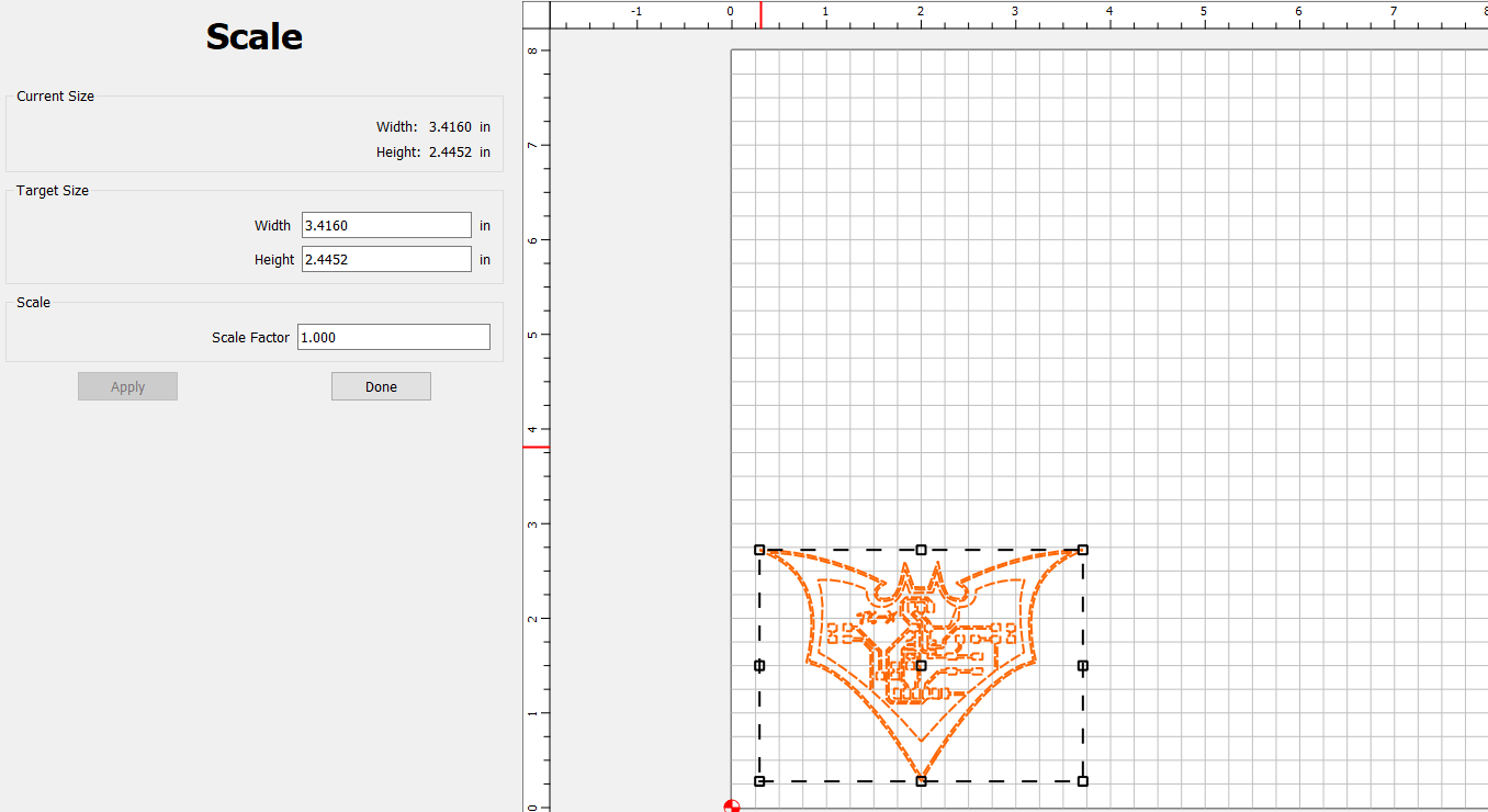
Since this was a .png image, it was added much larger than its original size, so I used the Scale tool to resize.
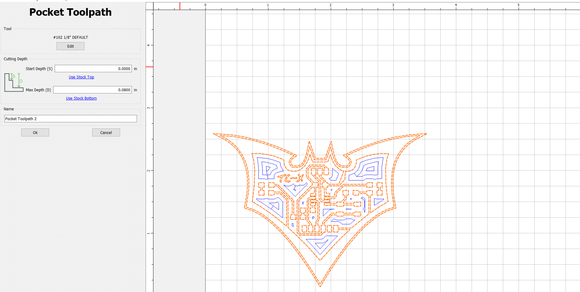
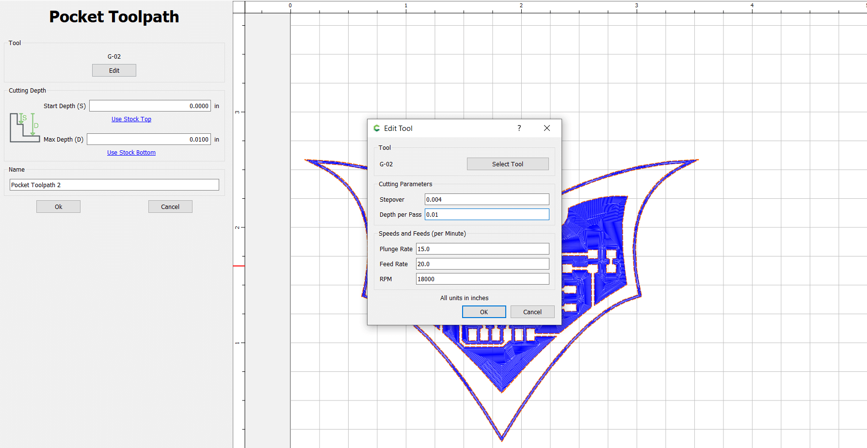
Located under the main menu tab there were two editing tabs, Design and Toolpath. I selected the Toolpath tab and then selected Pocket and this allowed me to setup the tool settings for the milling. For the Cutting Depth settings, I set the Start Depth to 0 (since this is for the pocket it would start at the max level) and the Max Depth to o.o1 inches (I arrived at this measurement after some tests, by default it was 0.08). I then clicked on Edit Tool to select and setup the bit I needed.
On clicking Edit the Edit Tool window opened and I selected Select Tool and its window opened. This window contained various categories with a selection of bits. The bit I was going to use for the milling was not found on the listing, so I had to create a new tool and add to the list. The main settings for my new bit tool was that it had to be an end-mill with a diameter of 0.2mm. I had to also setup some default settings such as stepover and RPM and some others. These settings are editable and can be changed depending on the task.
The image below shows the default settings added to the bit tool.
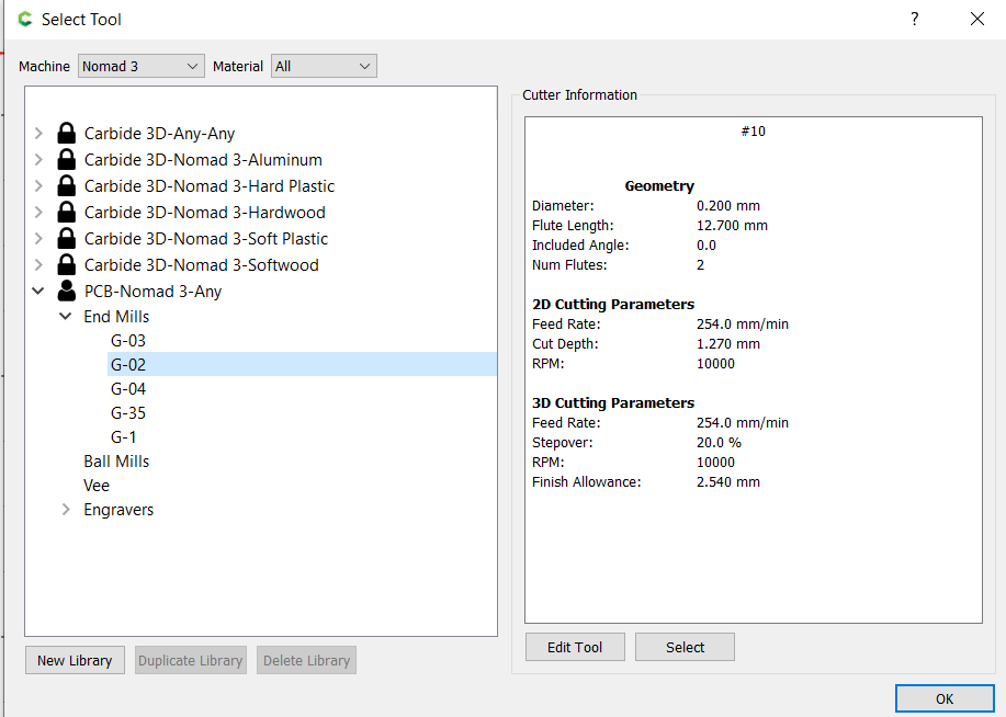
Upon confirming the Select Tool settings, I returned to the Edit Tool window. I set the Stepover to 0.004 and the Depth Per Pass to 0.01 (same as the Max Depth since its going to be one level). I also set the Plunge Rate to 15, the Feed Rate to 20 and the RPM to 18000. Since the bit was this thin, the high RPM would allow it to cut through faster as it moves making it more unlikely to break.
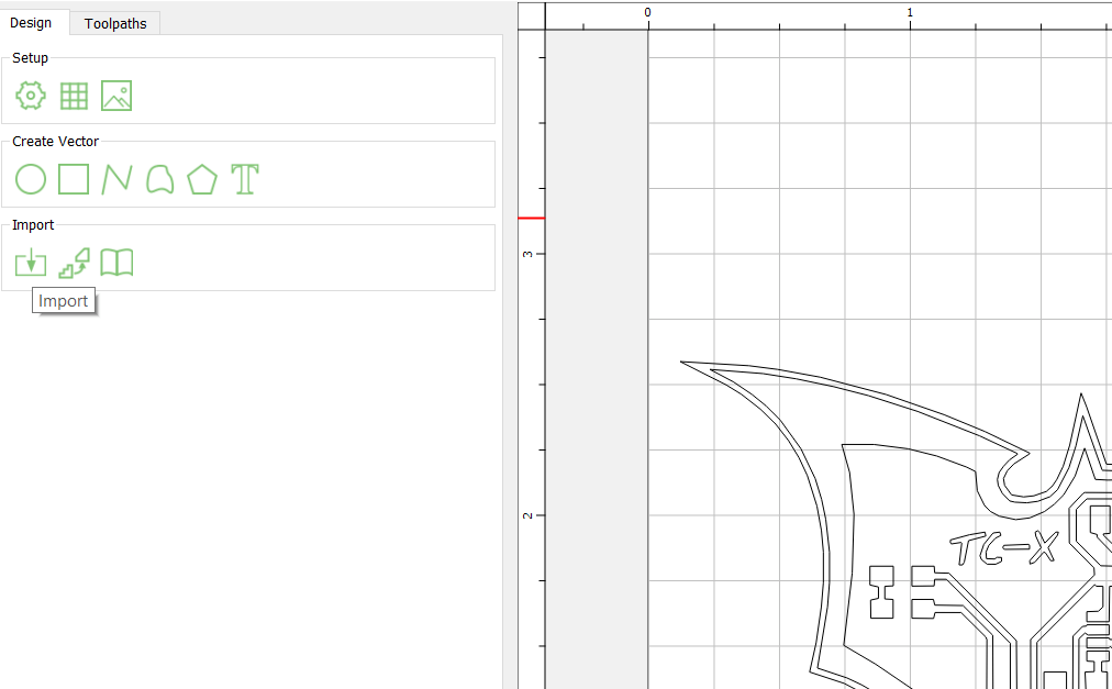
Now that I had the Pocket Toolpath setup, I went back to the Design tab and imported the .svg outline to cut the shape.
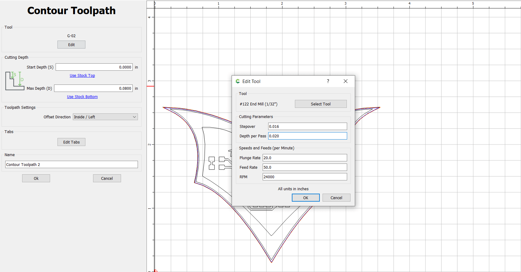
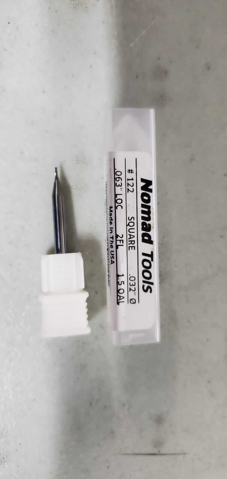
I went back to the Toolpath tab and added a Contour toolpath for the .svg file. I then selected Edit then Select Tool from the Edit Tool window. Under the Hard Plastic category, I selected The #122 bit.
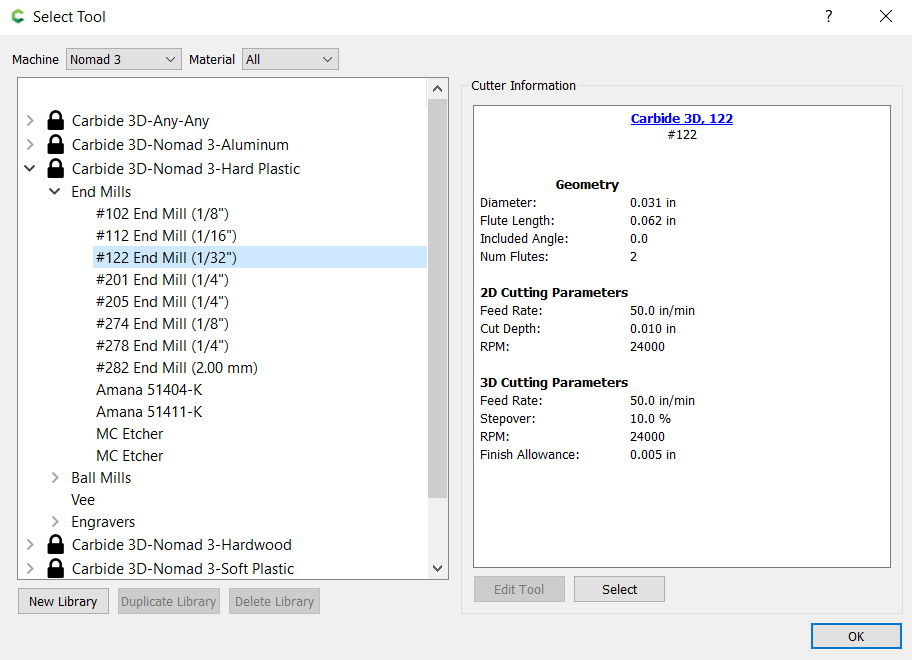
On the Edit Tool window I set the Depth Per Pass to 0.02 (which is quarter the max depth which means it needed 4 passes to cut out the shape). I left the rest of settings at their defaults.
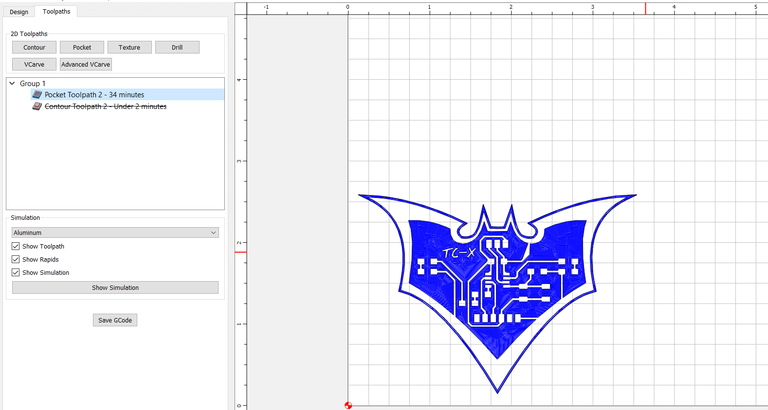
I had set up my toolpaths, a Pocket and a Contour. I disabled one toolpath at a time in order to Export G-Code for the other. So I had 2 G-Code files to be used on the Milling Machine.
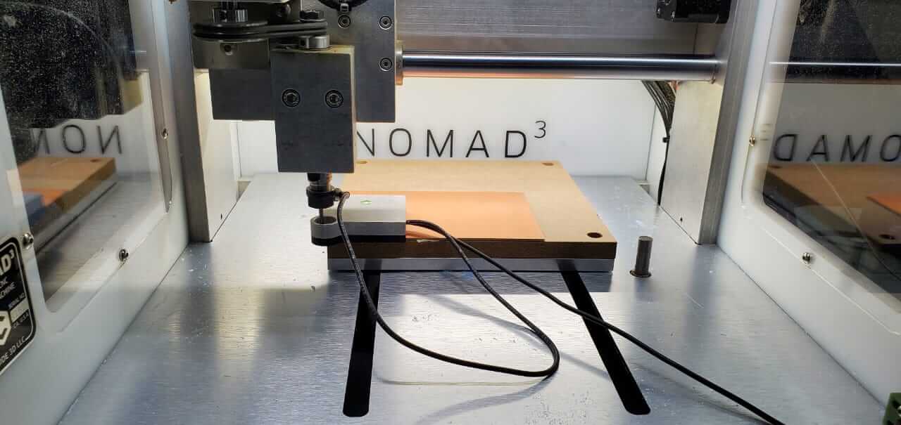
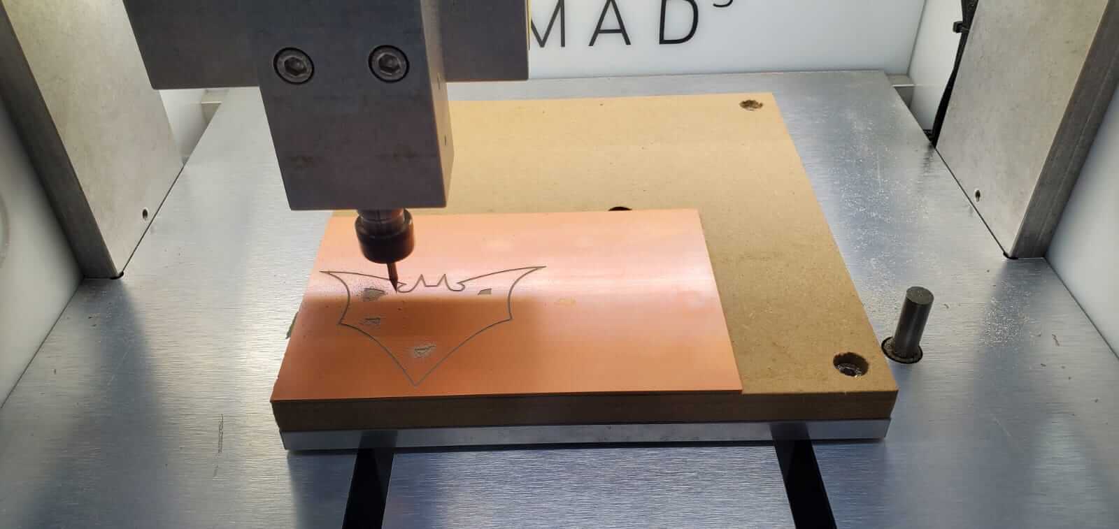
I placed and stuck my PCB sheet onto the bed of the Nomad 3. I then placed the probe at the corner so that the machine can detect and measure the materials position of the bed.
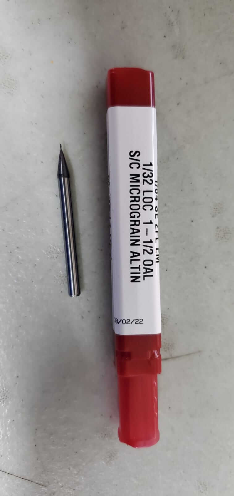
These were the two bits that were used for the milling process. A 1/64 inch diameter with a 1/32 LOC for the pocket and the #122 for the contour.
I clicked the Load New Tool for the machine to measure the bit that was being used. Load New File was used to add the G-Code file. Start was clicked to initiate the file.
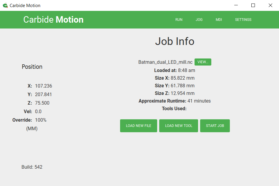
The Run Job window was opened to start and view the milling progress.
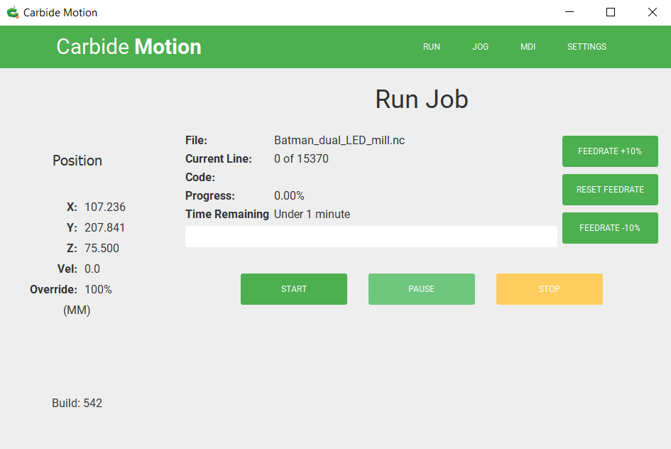
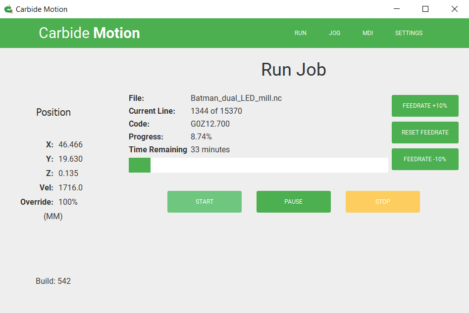
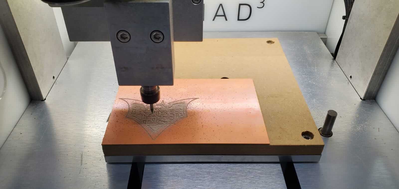
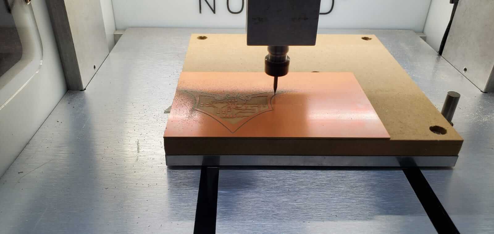
The Pocket G-Code file was sent to engrave around the circuit routes and traces. When the Pocket process was completed the bit was changed to the #122 and the Contour G-Code was loaded and sent to cut the outline shape.
The milled board was washed with soap and water to clean and remove any particles or finger oils that may have been on the surface due to touch. Dust or oils may prevent solder from holding properly.
I used a bevelled edge solder tip to solder my components. I used this tip instead of the common pointed or fine tip because personally I found it easier to paste solder on edges and also to wipe off or clean excess solder from a node or pin . I can also turn the tip on the edge of the bevel to use the thinner side if I needed to do very fine solder.

My board required the following components:
These components are really tiny so a magnifying glass with good lighting and some helping hand grips were needed.

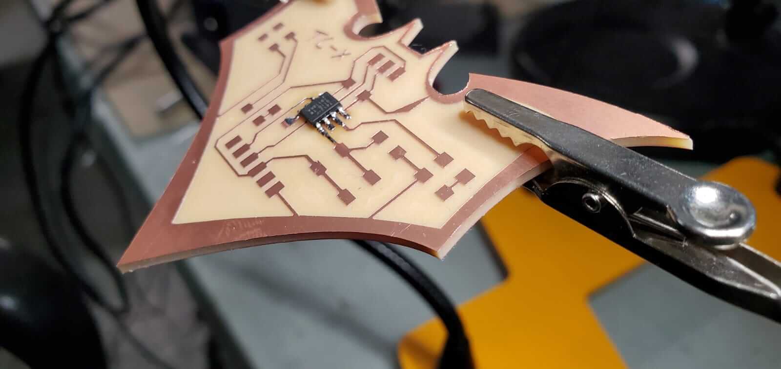
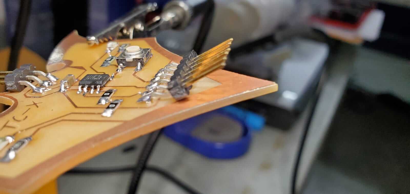
I soldered the ATTiny412 chip first because that was the most important and most delicate component on the board. I then proceeded to solder the other components. Due to the shape of my board, I had to place the Serial port (6-pin horizontal male header) upside-down causing the pins to point at about a 30 deg angle. This was done so that the Serial cable or jack can be attached easily.
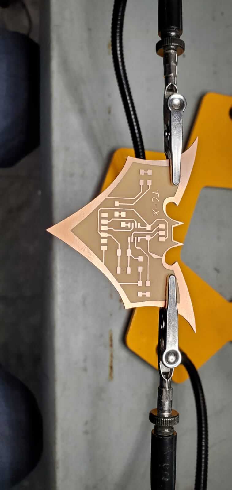
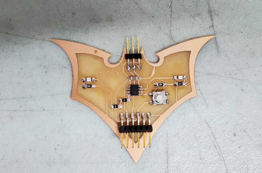
My completed Batman Dual LEDs ATTiny412 board.
Now that my board was completed, it was time to test if it works. Procedures for programming the board using Arduino IDE can be found in Week 4 Embedded Programming.
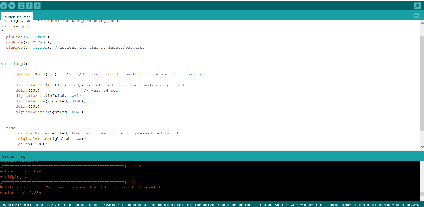
            int swt = 3;
            int leftled = 2;
            int rightled = 4; //declares the pins being used.
            void setup()
            {
                pinMode(3, INPUT);
                pinMode(2, OUTPUT);
                pinMode(4, OUTPUT); //assigns the pins as inputs/outputs.
            }

            void loop(){

                if(digitalRead(swt) == 1)  //declares a condition that if the switch is pressed.
           {
                digitalWrite(leftled, HIGH); // left led is on when switch is pressed
                delay(400);                 // wait .4 sec.
                digitalWrite(leftled, LOW);
                digitalWrite(rightled, HIGH);
                delay(400);
                digitalWrite(rightled, LOW);

            }
           else{
                digitalWrite(leftled, LOW); // if switch is not pressed led is off.
                digitalWrite(rightled, LOW);
                delay(1000);
            }

            }