
Compare the performance and development workflows for other architectures.
Link to Group AssignmentBrowse through the data sheet for your microcontroller.
Program a microcontroller development board.
to interact (with local input &/or output) and communicate (remotely).
Extra credit: use different languages &/or development environments.
Assignment Requirement
Status
Linked to the group assignment page
Completed
Documented what I learned from reading a microcontroller datasheet.
Completed
Programmed your board to interact and communicate
Completed
Described the programming process/es I used.
Completed
Included my source code.
Completed
Included ‘hero shot(s)’
Completed
For this assignment I was asked to go through a microcontroller datasheet. Firstly I needed to select my microcontroller. To select the chip I had to have at least some idea of what I am going to use it for. When selecting the chip I needed some basic requirements such as how many inputs or outputs I will need, and also the size of programs that may be used as well as how am I going to program it. These were just of the few basics I had to consider. Now it was not realistic for me to read an entire datasheet for a microcontroller because this is literaly hundreds of pages. I just browsed through looking for the key information relative to my requirements.
I decided that I will use the ATTiny 3216 AVR for my final project since I will require a few input/outputs. (Note: It is better to use a microcontroller with more I/Os than you need). I also read the ATTiny 412 datasheet since my first microntroller circuit design will be using this. I used the 412 because it is just an 8-pin chip and this would help me get some experience with designing a simple microcontroller circuit so it will be easier when I'm ready for the 3216 or more advanced chips.
The information you are about to view are details I highlighted from the respective datasheets that I saw relevant when using the chips in my designs.
An important feature I looked at was the CPU for these microcontrollers. This is where the instructions are processed to perform its tasks efficiently. The Chip contains an Advanced Virtual RISC (AVR) CPU. RISC stands for Reduced Instruction Set Computer. It is a microprocessor design that processes fewer instructions but at higher speeds.
All AVR devices use the AVR 8-bit CPU. The CPU is able to access memories, perform calculations, control peripherals, and execute instructions in the program memory.
To maximize performance and parallelism, the AVR CPU uses a Harvard architecture with separate buses for program and data. The instructions in the program memory are executed with a single-level pipeline. While one instruction is being executed, the next instruction is prefetched from the program memory. This enables instructions to be executed on every clock cycle.
AVR CPU Features
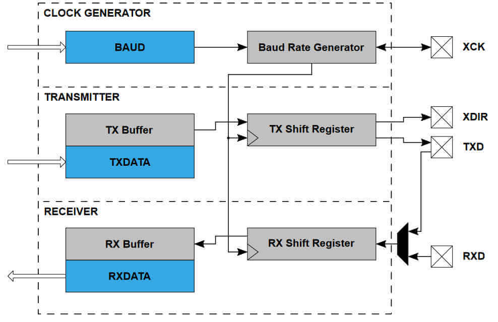
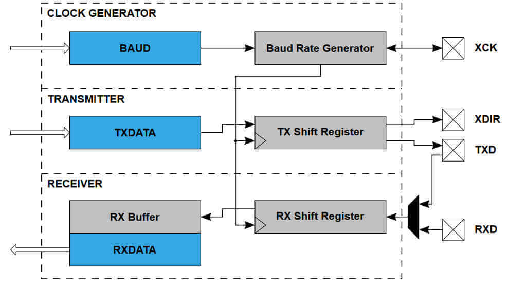
The Universal Synchronous and Asynchronous serial Receiver and Transmitter (USART) is a fast and flexible serial communication peripheral. The USART supports a number of different modes of operation that can accommodate multiple types of applications and communication devices. For example, the One-Wire Half-Duplex mode is useful when low pin count applications are desired. The communication is frame-based, and the frame format can be customized to support a wide range of standards. The USART is buffered in both directions, enabling continued data transmission without any delay between frames. Separate interrupts for receive and transmit completion allow fully interrupt-driven communication.
USART Features
CPU
Memories
System
Peripherals
I/O:
Temperature Range:
Speed Grades:
Multiplexing is basically using the same port or line for multiple active functions. The following diagram is a table displaying the functions of each pin:
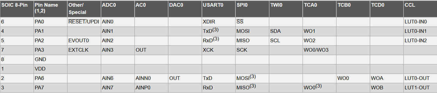
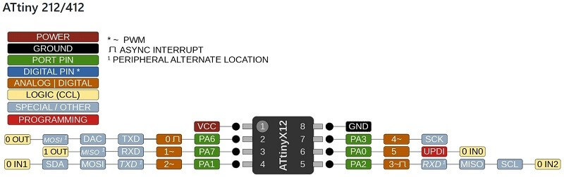
This is an 8 pin chip where 2 of the pins are for power source and 1 UPDI pin for programming, which leaves 5 pins for I/O. 2 pins may be assigned for serial communication, which will then leave 3 pins for purely I/O. This is enough pins for a switch and 2 LEDs to test the programming process.
The transmitter consists of a two-level write buffer, a Shift register, and control logic for different frame formats. The receiver consists of a two-level receive buffer and a Shift register. The status information of the received data is available for error checking. Data and clock recovery units ensure robust synchronization and noise filtering during asynchronous data reception.
CPU
Memories
System
Peripherals
I/O
Temperature Ranges:
Speed Grades:
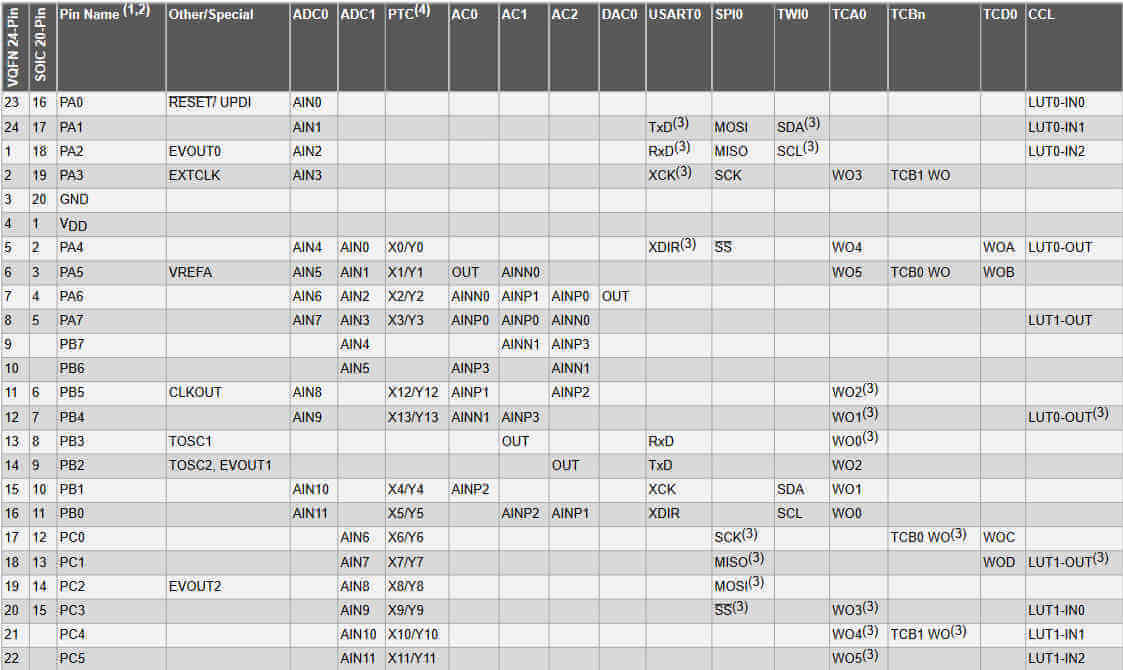
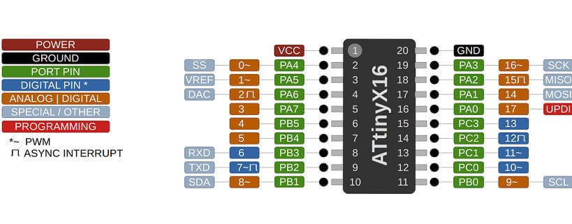
This chip has 20 pins which gives me the opportunity to attach quite a lot of I/O devices. 2 pins for power, 1 pin for UPDI, now I can assign the TX and Rx pins solely for serial communication and 2 pins for I2C communication and still have 13 pins free for I/O devices. This chip I know is perfect for my final project control system.
The transmitter consists of a single-write buffer (compared to the two-level buffer for the ATTiny 412), a Shift register, and control logic for different frame formats. The receiver consists of a two-level receive buffer and a Shift register. The status information of the received data is available for error checking. Data and clock recovery units ensure robust synchronization and noise filtering during asynchronous data reception.
Programming refers to sending instructions to the microcontroller. Embedded programming are set instructions that include the access and interaction with the microcontroller's input/output (I/O) interface.
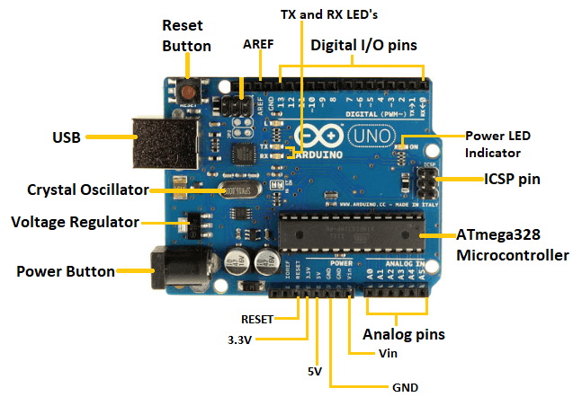
For this part of the assignment I used the arduino IDE (Integrated Development Environment) to program the microcontroller. The arduino IDE uses C Language to communicate with the chip. Since I was using this IDE I used an arduino uno development board to program.
The following picture shows the basic structure of the arduino uno board.
I decided to have the onboard LED blink with 1 second intervals.
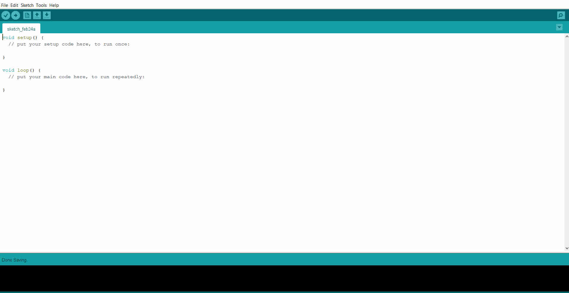
I installed and opened the Arduino IDE.
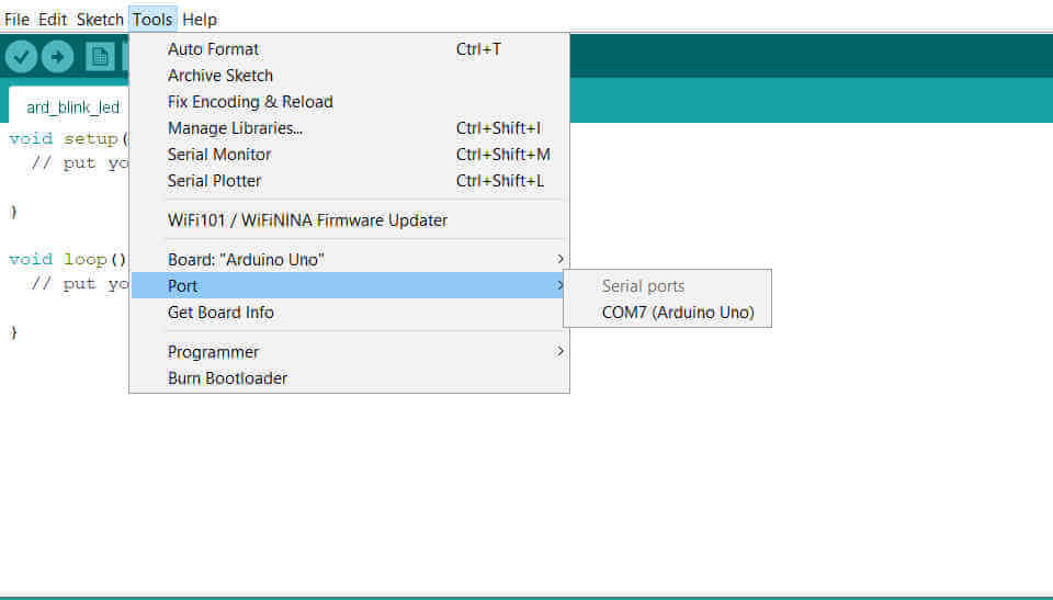
I saved the file and connected my arduino uno. I opened the tools menu tab and I selected the com Port.
NOTE: a com Port only appears when a communication device is connected.
I also selected Arduino Uno from the Board panel.
I entered my program for the blinking onboard LED. The onboard LED on the arduino uno is connected to Pin 13. The tick at the top left corner of the arduino IDE compiles the program and checks for errors. The arrow next to the tick uploads the program to the microcontroller.
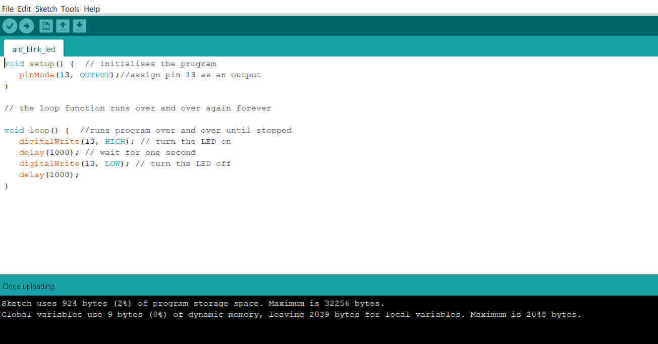
void setup() {  // program section that runs once
            pinMode(13, OUTPUT);//assign pin 13 as an output
        }

         // the loop function runs over and over again forever

         void loop() {  //runs program over and over until stopped
            digitalWrite(13, HIGH); // turn the LED on
            delay(1000); // wait for one second
            digitalWrite(13, LOW); // turn the LED off
            delay(1000);
         }
I uploaded the program to the arduino uno and the upload was successful.
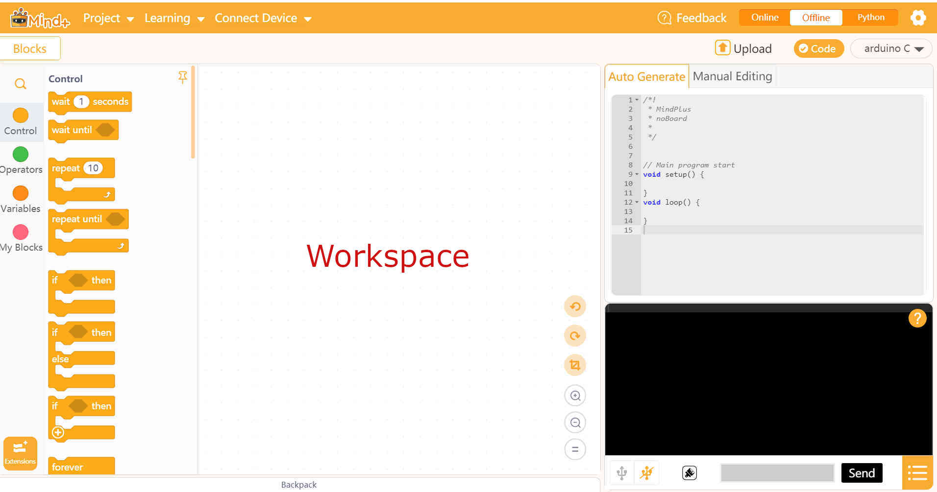
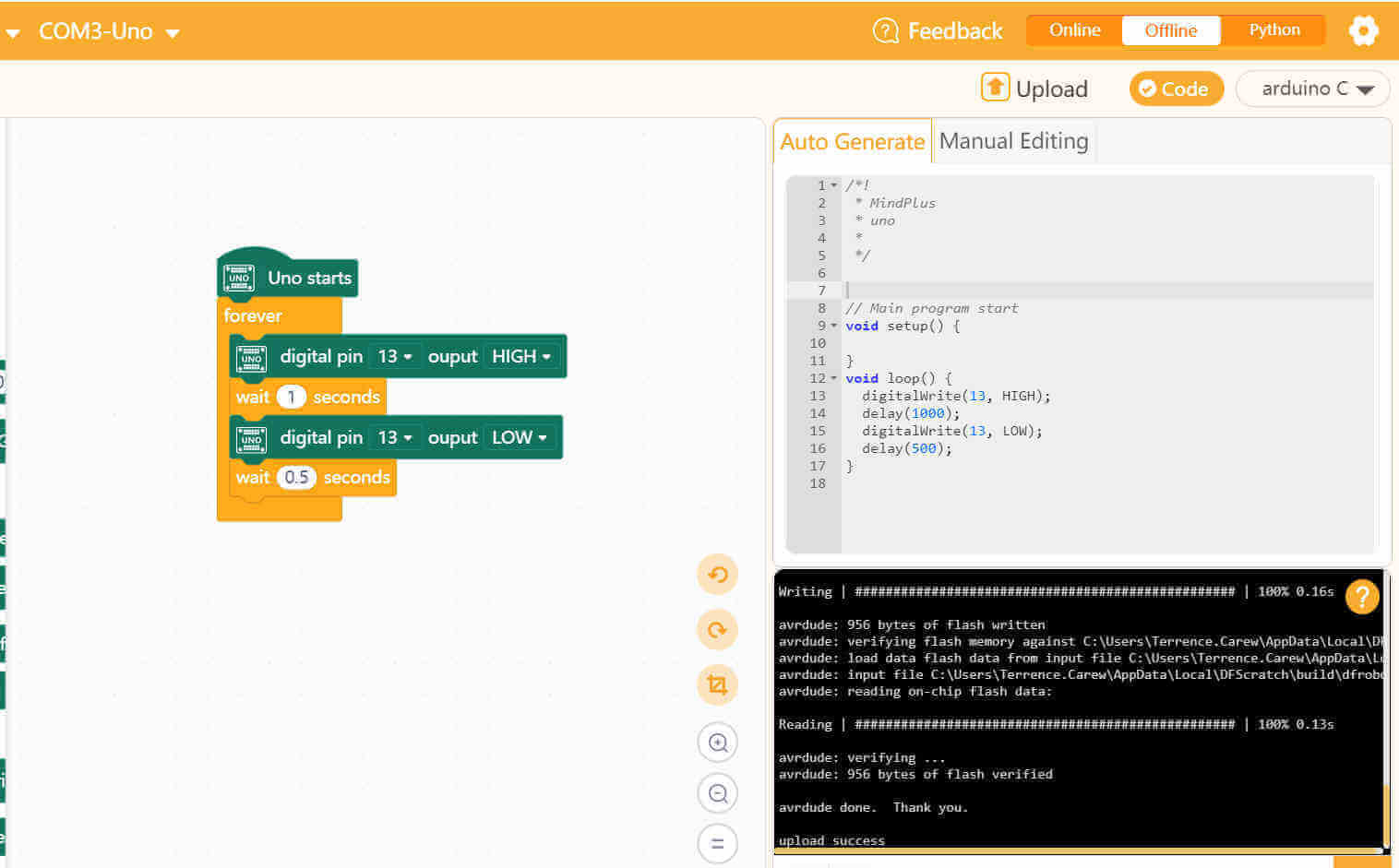
Besides the Arduino IDE there are a few different ways for programming the Arduino board. I decided to try another method of programming to make the Arduino perform the same task with the blinking LED. I installed Mind+ which is a Scratch based software that uses modular programming with drag and snap blocks.
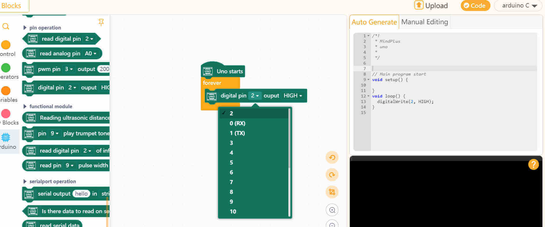
The interface includes the list and categories of code blocks to the left. The code blocks can be dragged onto the workspace in the middle. The blocks are designed to snap together to create a program. To the right there is a panel window that automatically generates the C language conversion of the block program in the workspace.
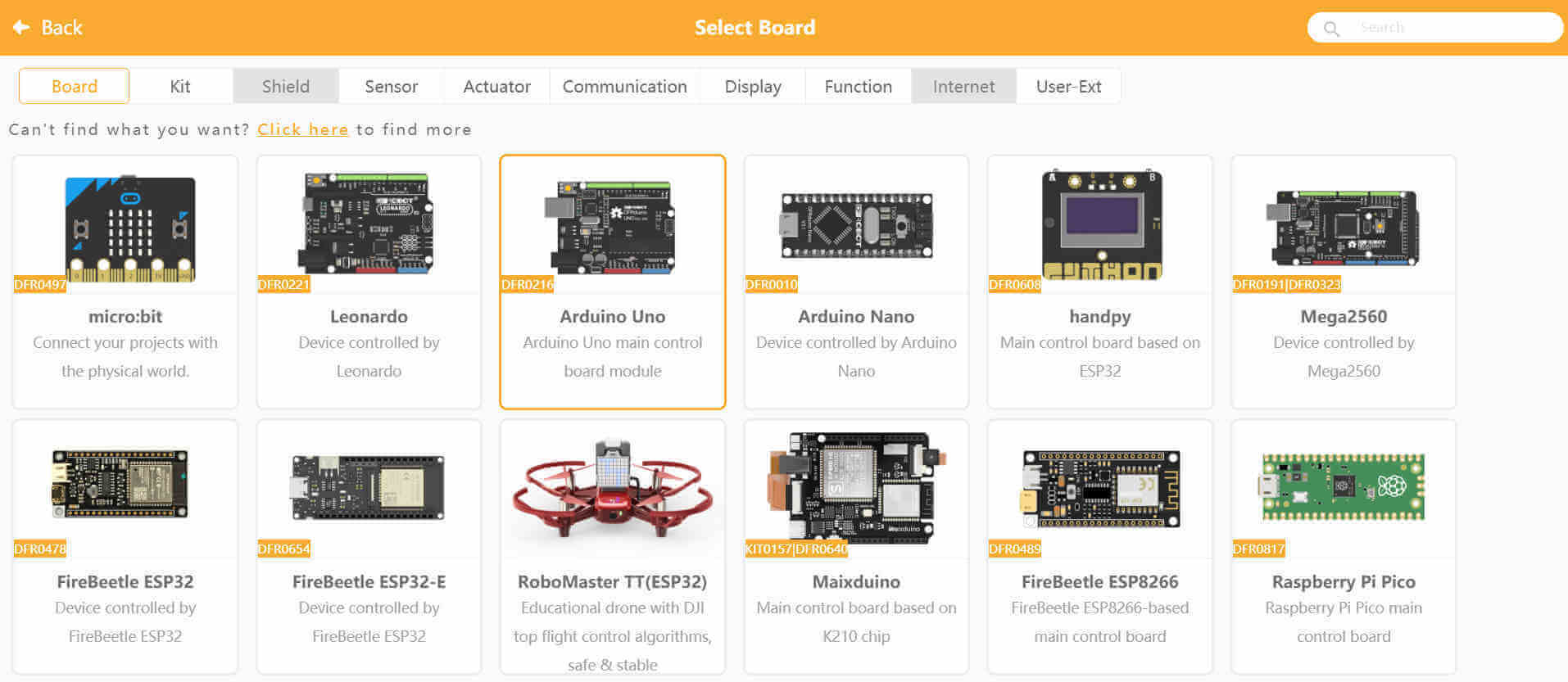
I opened the extensions tab that is located at the bottom of the blocks categories and this opened a window allowing me to select the board I am connecting. I selected the Arduino Uno.
I went back to the main interface and saw that there was a new category added to the list labelled Arduino. This category allowed me to access a lot more codes that were specific to Arduino. A "Uno starts" block snapped to a "Forever loop" block were automatically added to the workspace. These 2 blocks are the equivalent of "Void setup" and "Void loop" used in C for Arduino programs.
I dragged a "digital pin" block and snapped it inside of the "Forever loop" block. The default setting for this block is set to pin 2 and its status HIGH. As the block was added I noticed the C language window to the right updated with the equivalent C code as well.
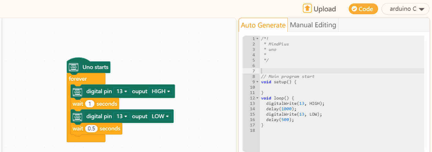
I changed the pin to pin 13 which again is the onboard LED pin of the Arduino Uno board. I added a "wait" block and set it to 1 second. This block is equivalent to "delay" function in C. I then added another "digital pin" block but this time I set the status to LOW and this was followed by another "wait".
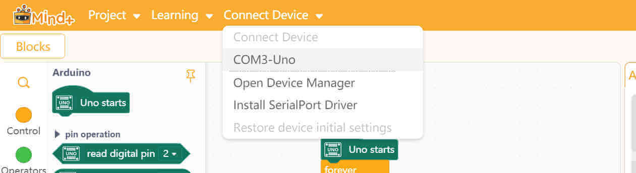
From the top menu bar I opened the drop-down menu for Connect Device and there I selected the Com port for my Arduino Uno board.
I then clicked on the Upload button located on top of the C language window to send the program to the board.
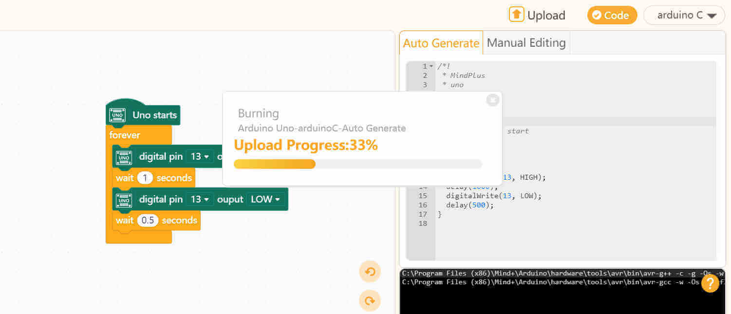
The program was uploaded successfully and the board worked. I did noticed there is a little difference between the code written in the Arduino IDE and the code automatically generated in Mind+. The generated code did not have to declare anything and the "void setup" was empty.
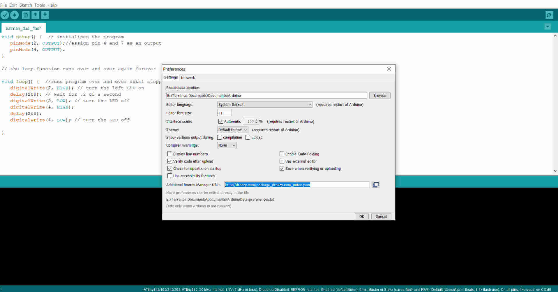
I tried uploading the program to my own ATTiny 412 microcontroller board. In order to do this I had to add an extension for
the arduino IDE to communicate with it.
I opened Preferences from the File menu tab and I pasted http://drazzy.com/package_drazzy.com_index.json in the
Additional Boards Manager URLs area. This gave me access to install the MegaTinyCore extension.
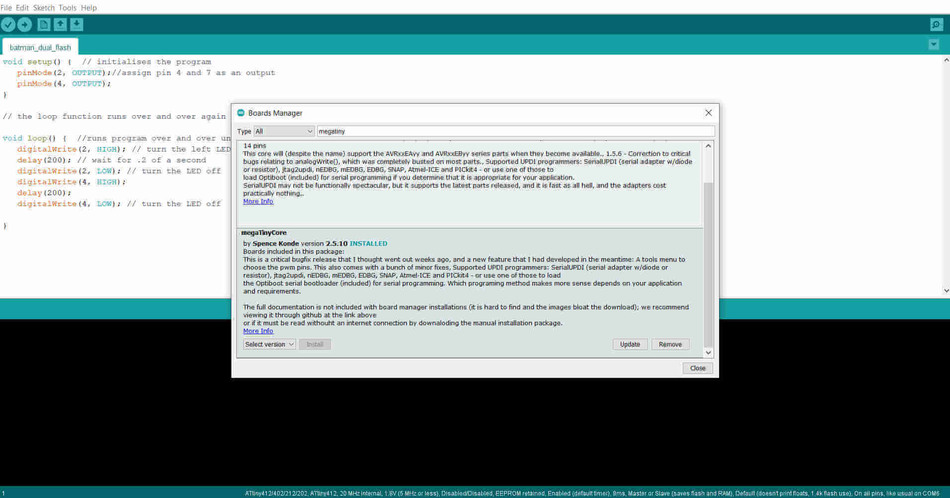
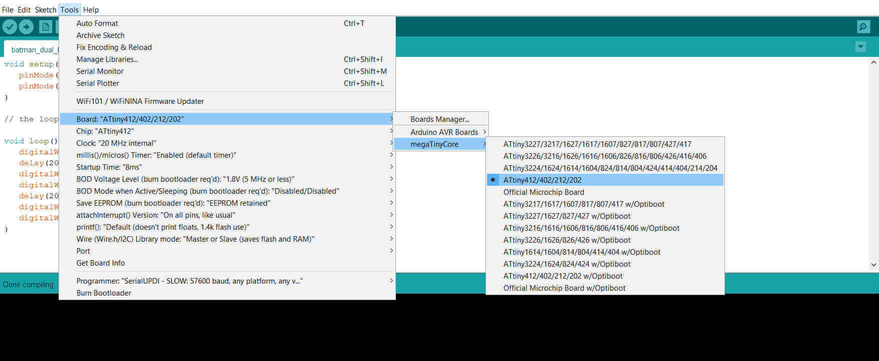
To locate the extension, I opened the Tools menu tab and selected Boards Manager from the Boards panel. I then typed "megatiny" and from the list of items that appeared I installed the MegaTinyCore from Spence Konde.
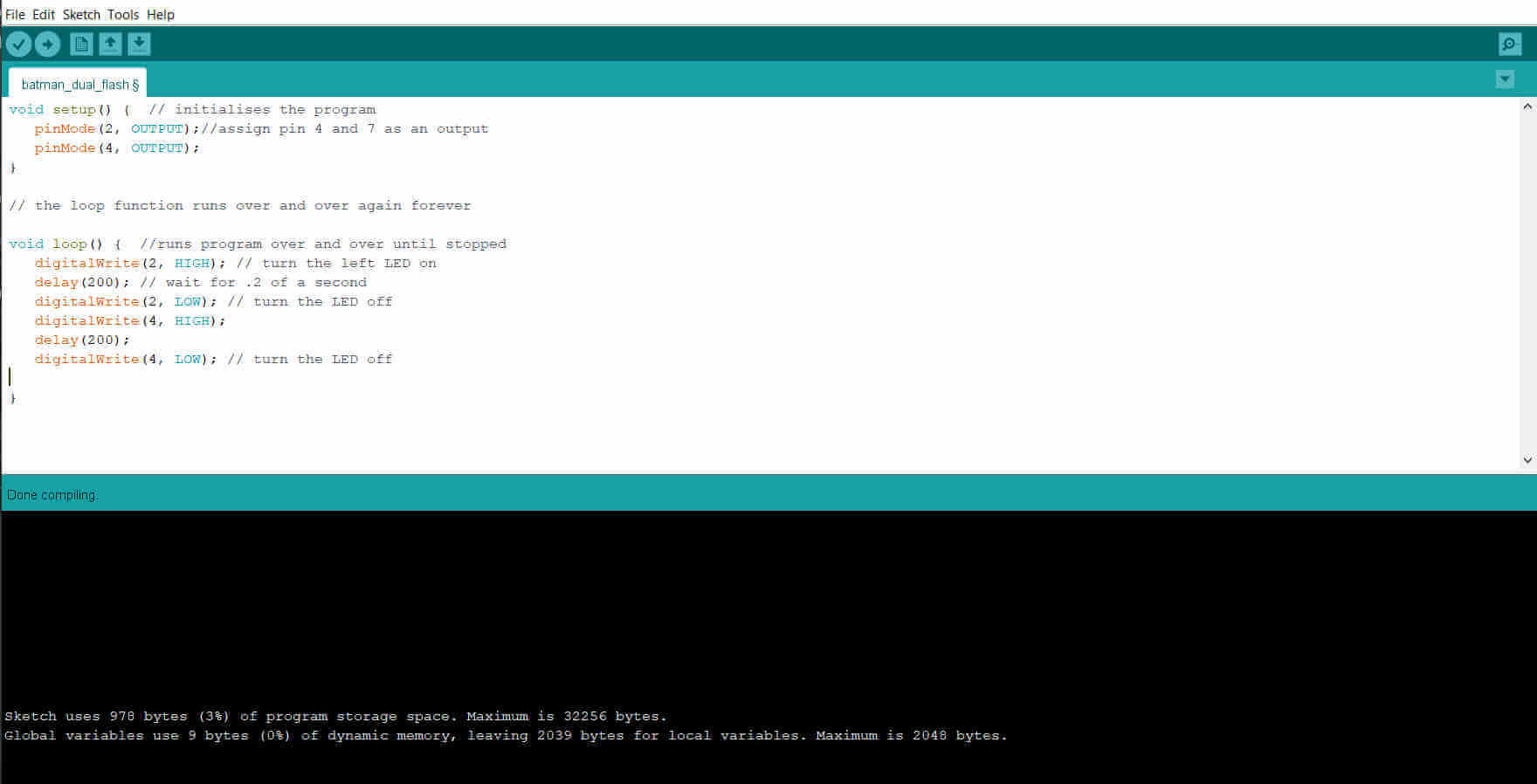
My ATTiny 412 board has 2 LEDs so I added another LED to the program I used for the arduino uno.
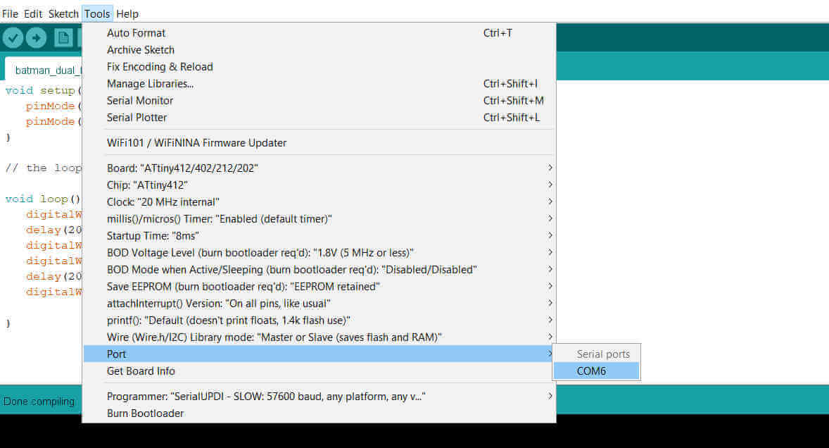
I opened the MegaTinyCore from the Boards panel and selected the series line containing the ATTiny 412 and I selected the com Port.
void setup() {  // program section that runs once
            pinMode(2, OUTPUT);//assign pin 4 and 7 as an output
            pinMode(4, OUTPUT);
         }

         // the loop function runs over and over again forever

         void loop() {  //runs program over and over until stopped
            digitalWrite(2, HIGH); // turn the left LED on
            delay(200); // wait for .2 of a second
            digitalWrite(2, LOW); // turn the LED off
            digitalWrite(4, HIGH);
            delay(200);
            digitalWrite(4, LOW); // turn the LED off
         }
I connected my board via its UPDI (Unified Program and Debug Interface) port using a USB to Serial UART converter to the computer. I then proceeded to upload the program to my ATTiny 412 board and was successful.
Serial communication refers to communicating data one bit at a time. Generally this incorporates protocols such as SPI (Serial Peripheral Interface), I2C (Inter-Integrated Circuit) and UART (Universal Asynchronous Reciever Transmitter) or USART (Universal Synchronous Asynchronous Reciever Transmitter) which uses the transmitter (TX) and Receiver (RX) port. The ATTiny412 features USART which makes it capable of doing both Synchronous and Asynchronous data and signal exchange. This process can be used to send or receive signals between microcontrollers or between a microcontroller and the computer or any device that is capable of serial communication.
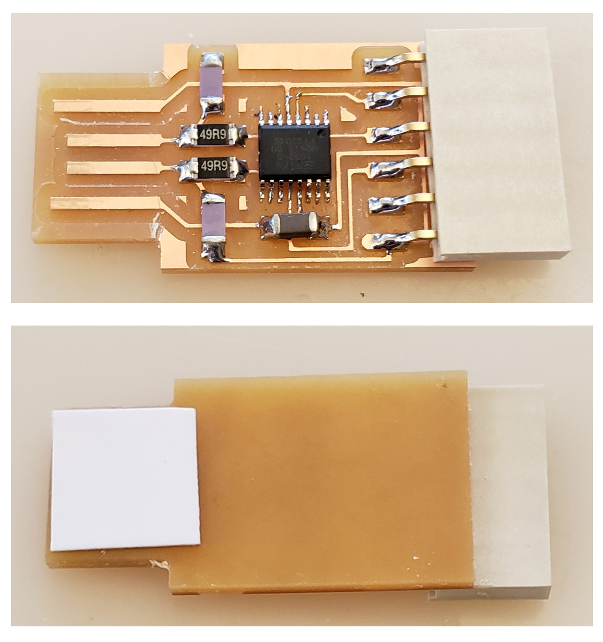
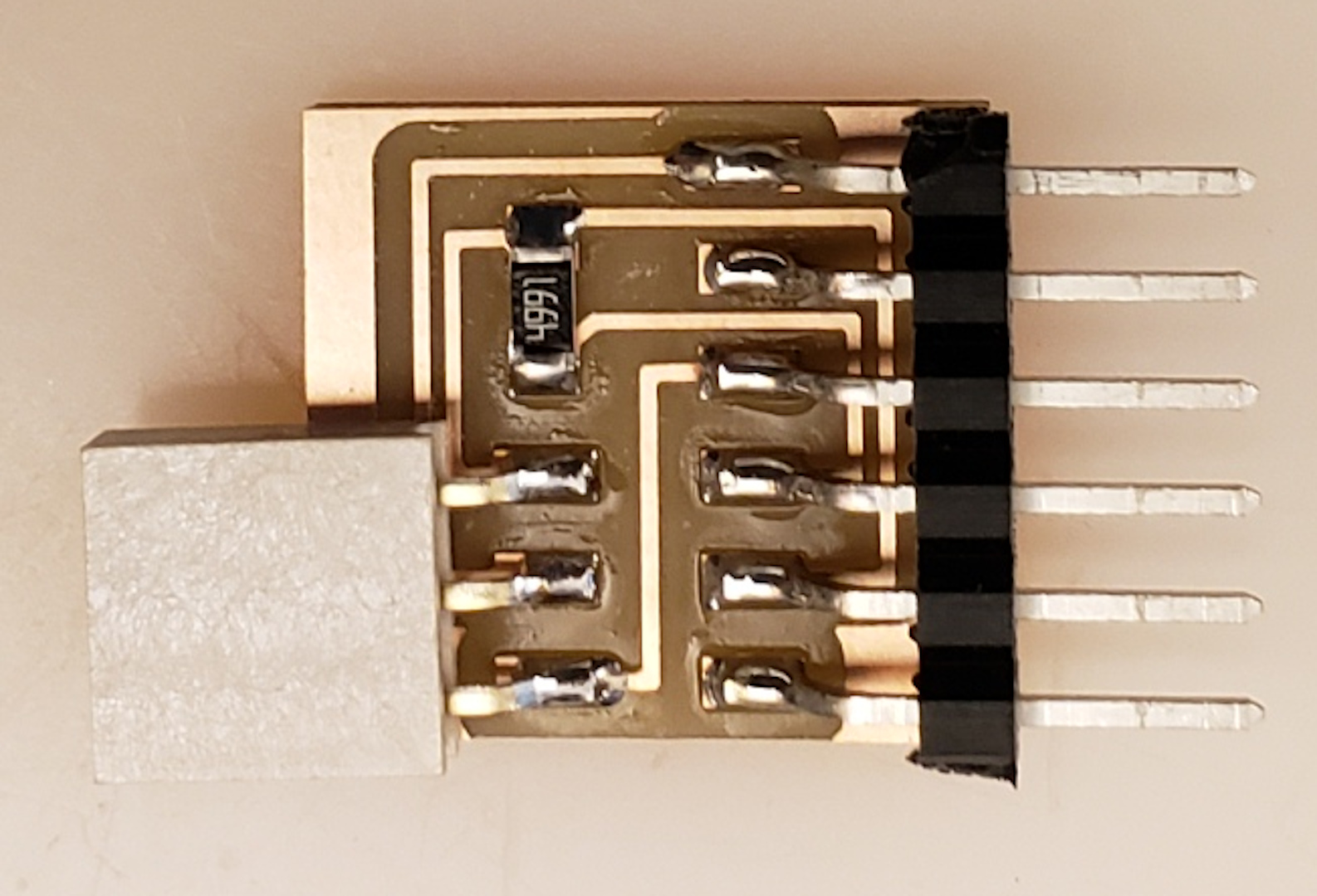
I used my development board to communicate with the computer. In order to connect the board to the computer I used a USB to Serial UART converter connector. The converter I used contains an FTDI (Future Technology Devices International Limited) chip. This chip is a microprocessor that converts the signals transmitted from my development board's microcontroller to USB signal and vice versa. I built my USB to serial UART converter from the FTDI design given at Fab Academy using the FT230XS chip. Drivers for this chip and the original FTDI cable can be found here. The converter was used to program the microcontroller, however, a UPDI adapter was required. The UPDI board contains a 4.99K ohm resistor that connects the transmitter and receiver pins, and the receiver is connected to the microcontroller's UPDI pin.
Connecting and programming my board was simple enough but this involved mostly seeing what the board receives, I needed to see what the board transmits via serial communication. One way of doing this is by using the Arduino IDE built in serial monitor. To use the serial monitor I added it to my program. To start the serial communication and set or change serial BAUD speed I included the following code to my program:
Serial.beginThe BAUD speed is the rate at which data is transferred and is measured in bits per second (bps). The default BAUD speed is set at 9600 bps
To veiw on the serial monitor what was being sent from my board I added one of the following codes:
        Serial.println    //displays each item or message on a new line.

        Serial.print    //everything on same line.
I created a program to run on my Batman board to flash both leds one at a time when the switch is pressed. The program would also allow the board to send a message to the serial monitor giving the leds' statuses.
           int swt = 3;
           int leftled = 2;
           int rightled = 4; //declares the pins being used.
           void setup()
           {
            pinMode(3, INPUT);
            pinMode(2, OUTPUT);
            pinMode(4, OUTPUT); //assigns the pins as inputs/outputs.
            Serial.begin(9600); // begins communication with the serial monitor.
           }

           void loop()
           {
            Serial.print("Status:");

            if(digitalRead(swt) == 1)  //declares a condition that if the switch is pressed.
           {
            digitalWrite(leftled, HIGH); // left led is on when switch is pressed
            Serial.println("LEFT ON");  // sends a message to serial monitor to say the led is on.
            delay(400);                 // wait .4 sec.
            digitalWrite(leftled, LOW);
            digitalWrite(rightled, HIGH);
            Serial.print(Status:)
            Serial.println("RIGHT ON");
            delay(400);
            digitalWrite(rightled, LOW);

           }
           else{
            digitalWrite(leftled, LOW); // if switch is not pressed led is off.
            digitalWrite(rightled, LOW);
            Serial.println("OFF");
            delay(1000);
           }

          }
The program was uploaded successfully and the board was was read from the serial monitor. To access the serial monitor, I opened the Tools menu tab and clicked on Serial Monitor.
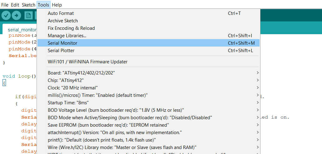 The monitor indicated LEFT LED ON or RIGHT LED ON when the switch was pressed and LEDs were lit accordingly,
and OFF when both LEDs were off.
The monitor indicated LEFT LED ON or RIGHT LED ON when the switch was pressed and LEDs were lit accordingly,
and OFF when both LEDs were off.
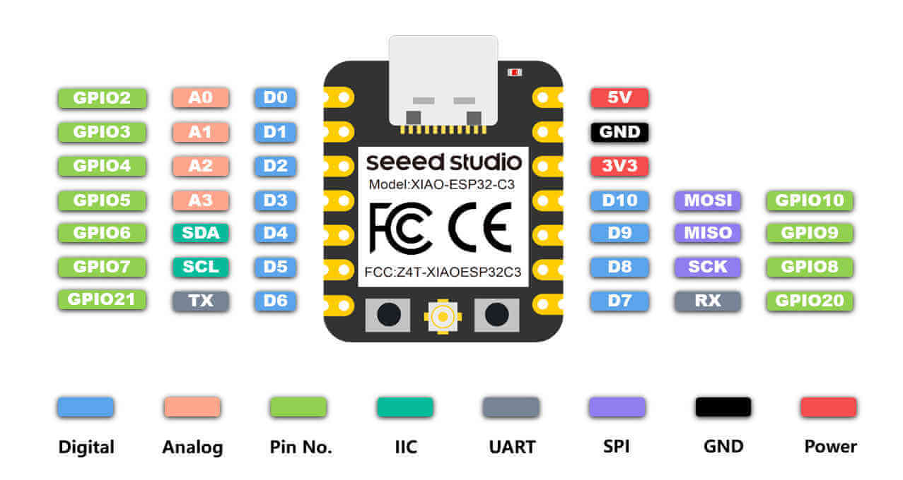
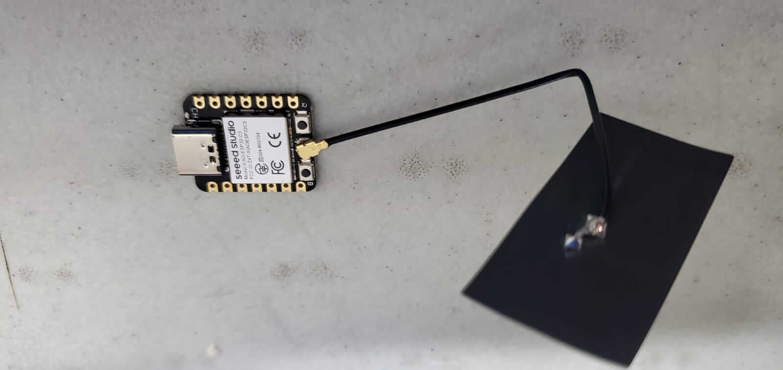
The ESP32 chips are low powered chips that are well known for its wifi and bluetooth capabilities. XIAO means 'tiny but powerful'. The XIAO boards are basically thumbsize boards containing powerful chips which may include SAMD21, nRF52840, RP2040 and ESP32C3.
I decided to try programming the XIAO ESP32C3 to test its wifi connection. The board includes both 3.3V and 5V out, along with 11 I/O ports. It is also compatible for I2C, UART and SPI.
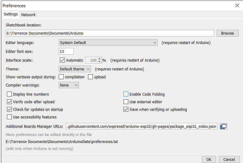
I used the Arduino IDE to program the XIAO. I opened Preferences from the File menu tab and I pasted https://raw.githubusercontent.com/espressif/arduino-esp32/gh-pages/package_esp32_index.json in the Additional Boards Manager URLs area. This gave me access to install the ESP32 Arduino extension.
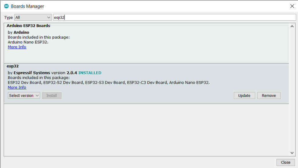
I then opened the Tools menu tab and selected Boards Manager from the Boards panel. I then typed "ESP32" and from the list of items that appeared I installed the ESP32 from Espressif Systems.
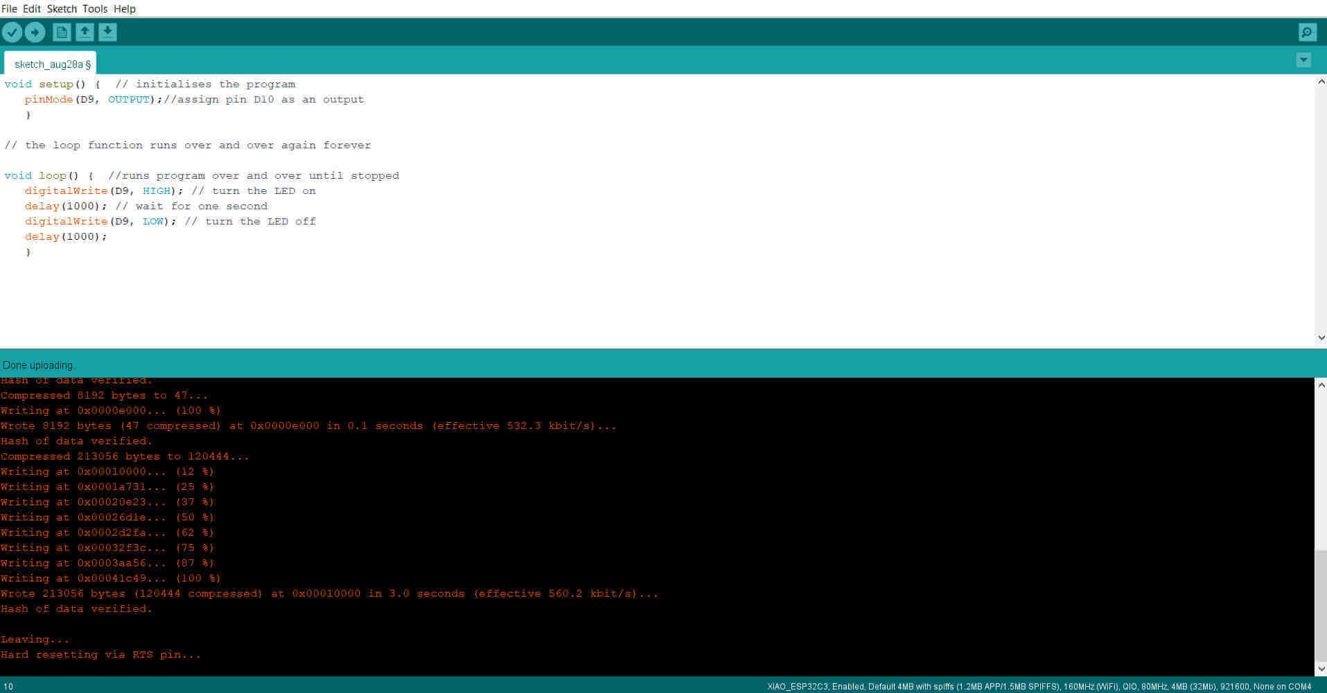
I entered the program to blink an LED using the pin D9. This was my test program.
            void setup() {  // program section that runs once
                pinMode(D9, OUTPUT);//assign pin D10 as an output
                }

             // the loop function runs over and over again forever

             void loop() {  //runs program over and over until stopped
                digitalWrite(D9, HIGH); // turn the LED on
                delay(1000); // wait for one second
                digitalWrite(D9, LOW); // turn the LED off
                delay(1000);
                }
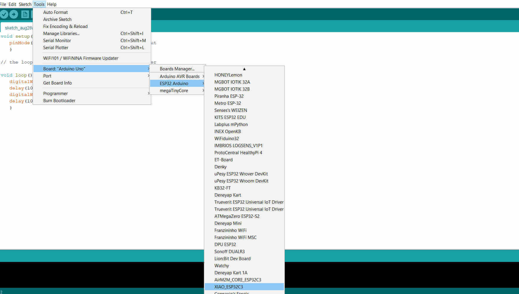
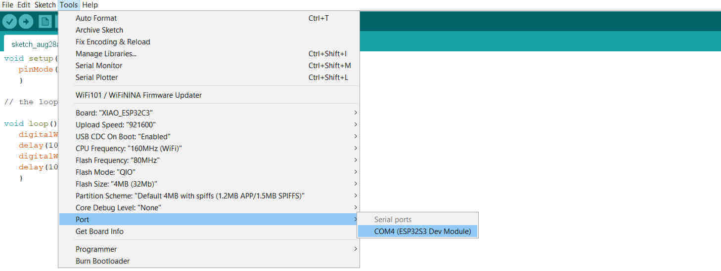
I opened the ESP32 Arduino from the Boards panel and selected the XIAO ESP32C3 all the way to the bottom of the list and I selected the com Port.
I then uploaded my program to the board and it was successful.
I attached an external LED to ground and D9 ports.
My XIAO proved to be in good working order so i moved on to test the wifi feature. The programs used I refered to Seeed Studio tutorial.
I first did a wifi scan to view available connections. I attached the little antenna that came with the XIAO.
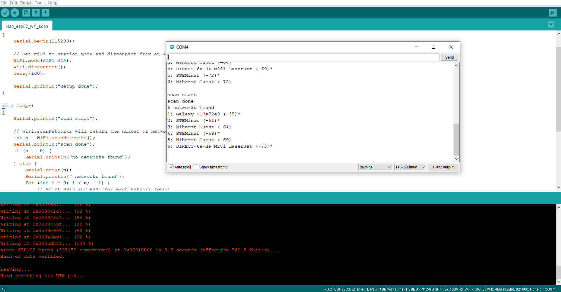
 I uploaded a program that scanned and displayed all available wifi on the serial monitor.
            #include "WiFi.h"

            void setup()
            {
                 Serial.begin(115200);

                // Set WiFi to station mode and disconnect from an AP if it was previously connected
                 WiFi.mode(WIFI_STA);
                WiFi.disconnect();
                delay(100);

                Serial.println("Setup done");
            }

            void loop()
            {
                Serial.println("scan start");

                // WiFi.scanNetworks will return the number of networks found
               int n = WiFi.scanNetworks();
               Serial.println("scan done");
               if (n == 0) {
               Serial.println("no networks found");
            }
               else {
               Serial.print(n);
               Serial.println(" networks found");
               for (int i = 0; i < n; ++i) {
               // Print SSID and RSSI for each network found
               Serial.print(i + 1);
               Serial.print(": ");
               Serial.print(WiFi.SSID(i));
               Serial.print(" (");
               Serial.print(WiFi.RSSI(i));
               Serial.print(")");
               Serial.println((WiFi.encryptionType(i) == WIFI_AUTH_OPEN)?" ":"*");
               delay(10);
            }
            }
               Serial.println("");

               // Wait a bit before scanning again
               delay(5000);
            }
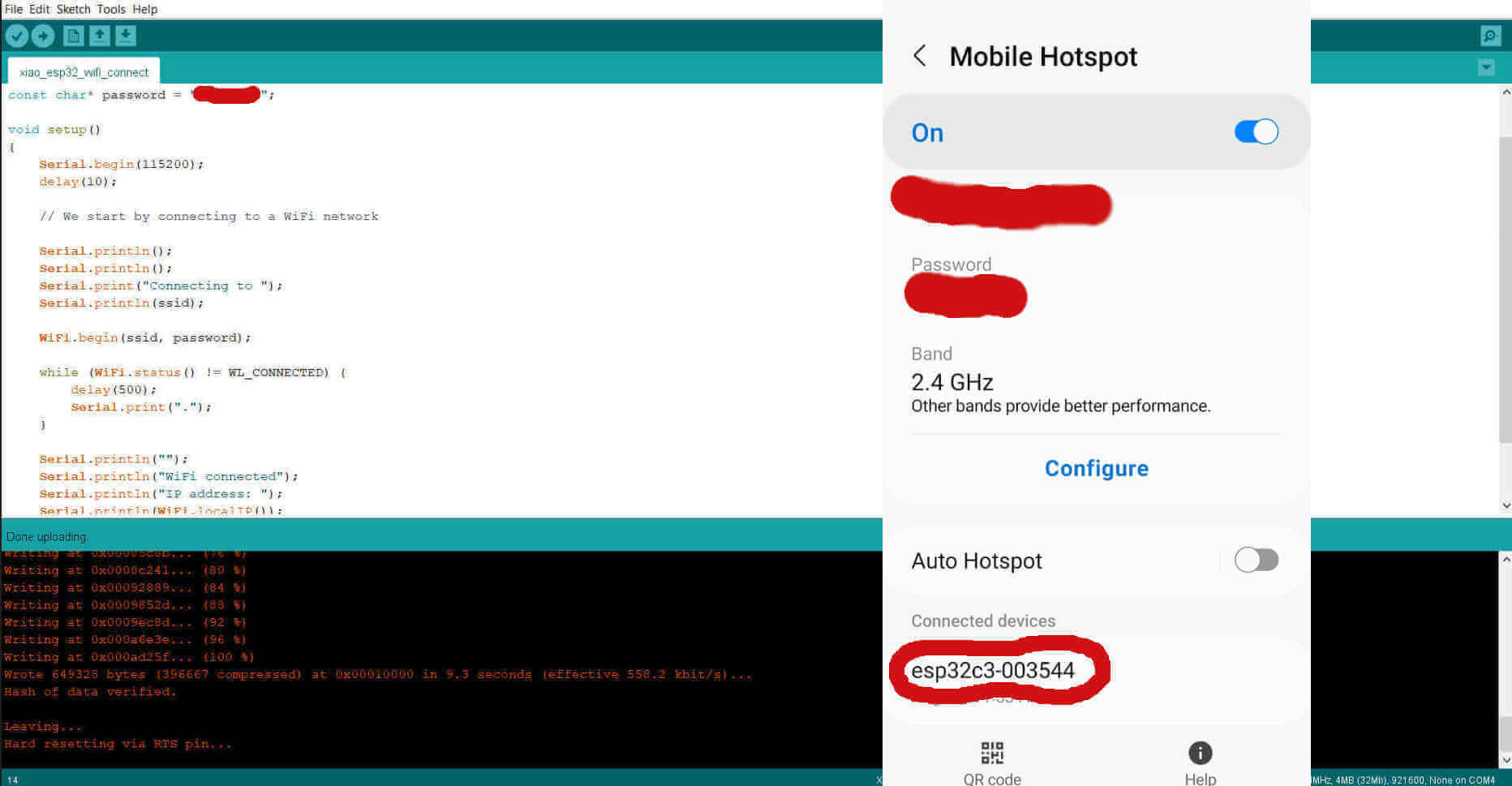
On successful scan I uploaded a program to connect to my phone. In the sketch I included my phones wifi name and password and I then turned on the hotspot.
            #include

                const char* ssid     = "wifi name";
                const char* password = "password";

                void setup()
                {
                    Serial.begin(115200);
                    delay(10);

                    // We start by connecting to a WiFi network

                    Serial.println();
                    Serial.println();
                    Serial.print("Connecting to ");
                    Serial.println(ssid);

                    WiFi.begin(ssid, password);

                    while (WiFi.status() != WL_CONNECTED) {
                        delay(500);
                        Serial.print(".");
                    }

                    Serial.println("");
                    Serial.println("WiFi connected");
                    Serial.println("IP address: ");
                    Serial.println(WiFi.localIP());
                }
                void loop()
                {
                  }
I uploaded and successfully connected to the XIAO to my phone.
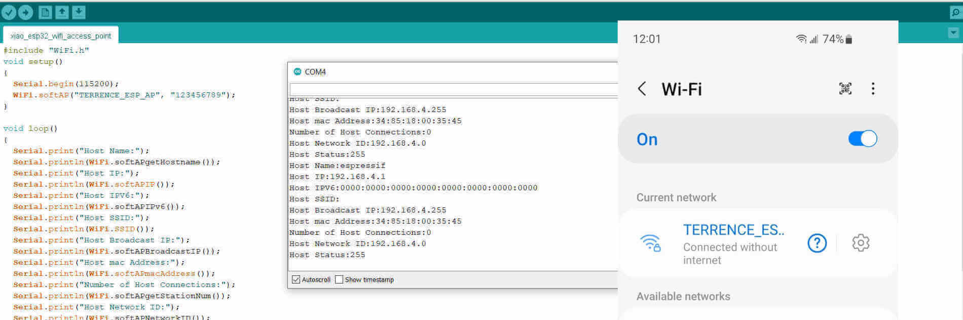
The third check was to try connecting my phone to the XIAO's wifi. This program allowed me to assign a name for the XIAO's signal as well as a password which was optional.
        #include "WiFi.h"
               void setup()
               {
                   Serial.begin(115200);
                   //wifi name and password
                   WiFi.softAP("TERRENCE_ESP_AP", "123456789");
               }

              void loop()
              {
                  Serial.print("Host Name:");
                  Serial.println(WiFi.softAPgetHostname());
                  Serial.print("Host IP:");
                  Serial.println(WiFi.softAPIP());
                  Serial.print("Host IPV6:");
                  Serial.println(WiFi.softAPIPv6());
                 Serial.print("Host SSID:");
                 Serial.println(WiFi.SSID());
                 Serial.print("Host Broadcast IP:");
                 Serial.println(WiFi.softAPBroadcastIP());
                 Serial.print("Host mac Address:");
                 Serial.println(WiFi.softAPmacAddress());
                 Serial.print("Number of Host Connections:");
                 Serial.println(WiFi.softAPgetStationNum());
                 Serial.print("Host Network ID:");
                 Serial.println(WiFi.softAPNetworkID());
                 Serial.print("Host Status:");
                 Serial.println(WiFi.status());
                 delay(1000);
             }
I uploaded the sketch and shortly after I saw the available signal on my phone and connected.