12. Output devices
This week I worked on defining my final project idea and started to getting used to the documentation process.
Individual assignment: add an output device to a microcontroller board you’ve designed and program it to do something.
Neopixel
For my final project, I will be using the neopixels, so I decided it will be a good idea to test them out this week. I attempted using the ATtiny44 board, but it did not work; and since my ATMEGA328p-AU board wasn’t done yet, I used the classic Arduino UNO.
Update: I tried again using the ATtiny44, and it worked.
ATtiny44
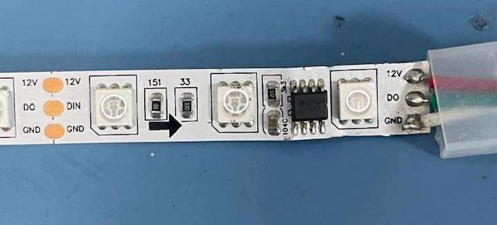
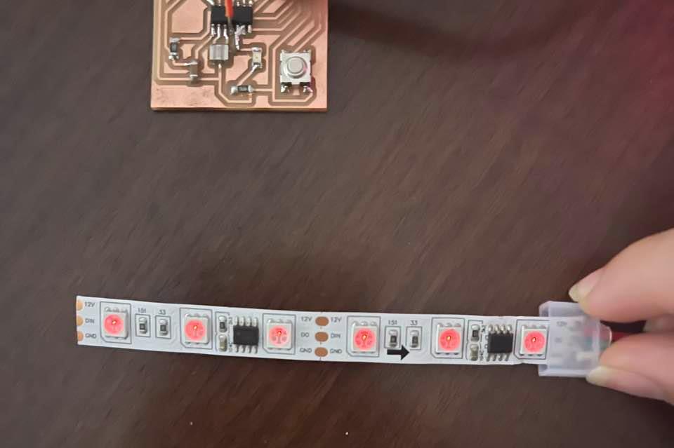
First, I cut the neopixel strip to be shorter. I wanted to run a test only so I cut it to only 6 neopixels. I tried doing it without cutting it first, but turns out the code requires setting the amount of pixels and it wont work if they mismatch.
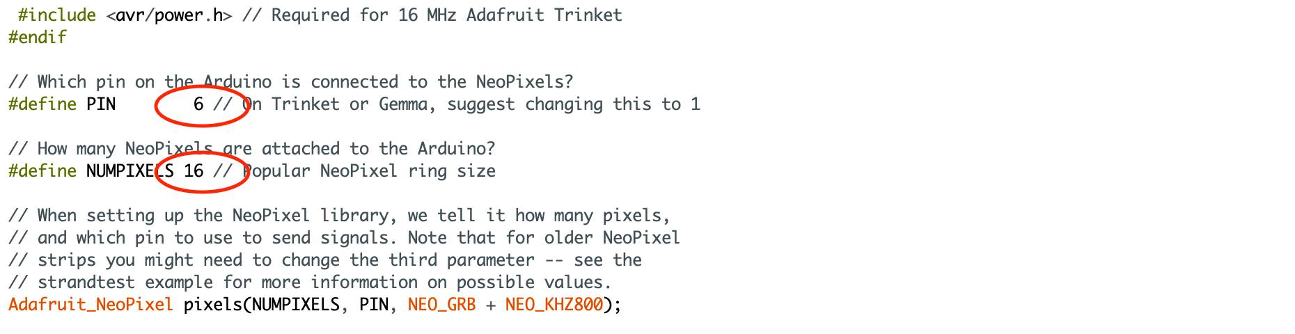
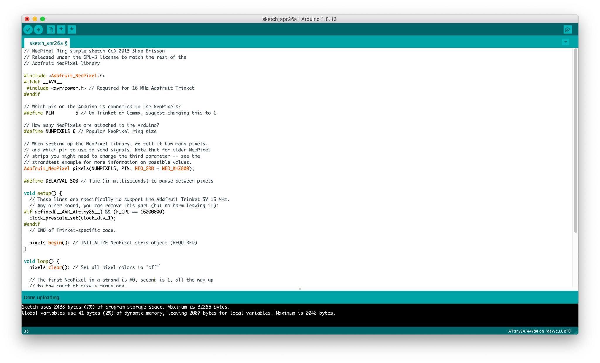
Then, I programmed the ATtiny44. First, I added the Adafruit Neopixel Library from the library manager on Arduino IDE. Then, I created a new sketch and launched the simple code from the examples of the Adafruit Neopixel library. I defined the pins in the following lines based on my connections.
My connections:
- GND pin on Neopixel to GND on ATtiny44
- +5V pin on Neopixel to 5V on ATtiny44
The DIN pin needed a PWM pin which meant pins 5-8 on the ATtiny. I only had a connection on pin 7 (MOSI) which was connected to the ISP but if I had connected that to the Neopixel, then I wouldn’t be able to supply power… right? I’m not sure how it works, but long story short, I didn’t connect the DIN to anything and it still worked :)
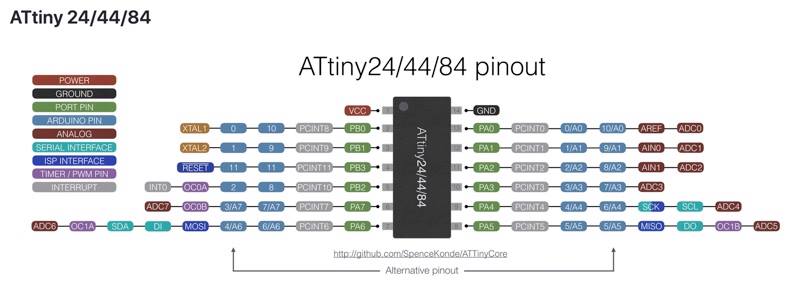
Using the above pinout the new lines are:
//Which pin on the Arduino is connected to the NeoPixels?

define PIN    7

//How many NeoPixels are attached to the Arduino?

define NUMPIXELS 6
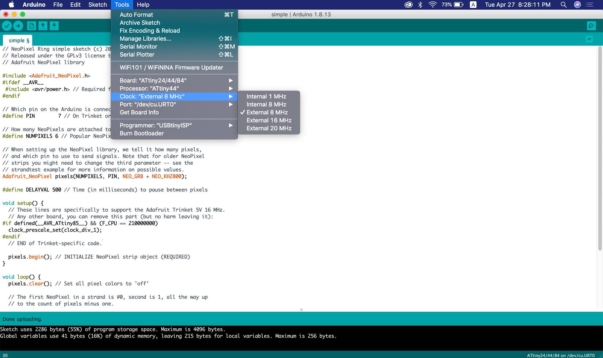
I tried uploading the code but another error appeared, the CPU Speed was not supported.
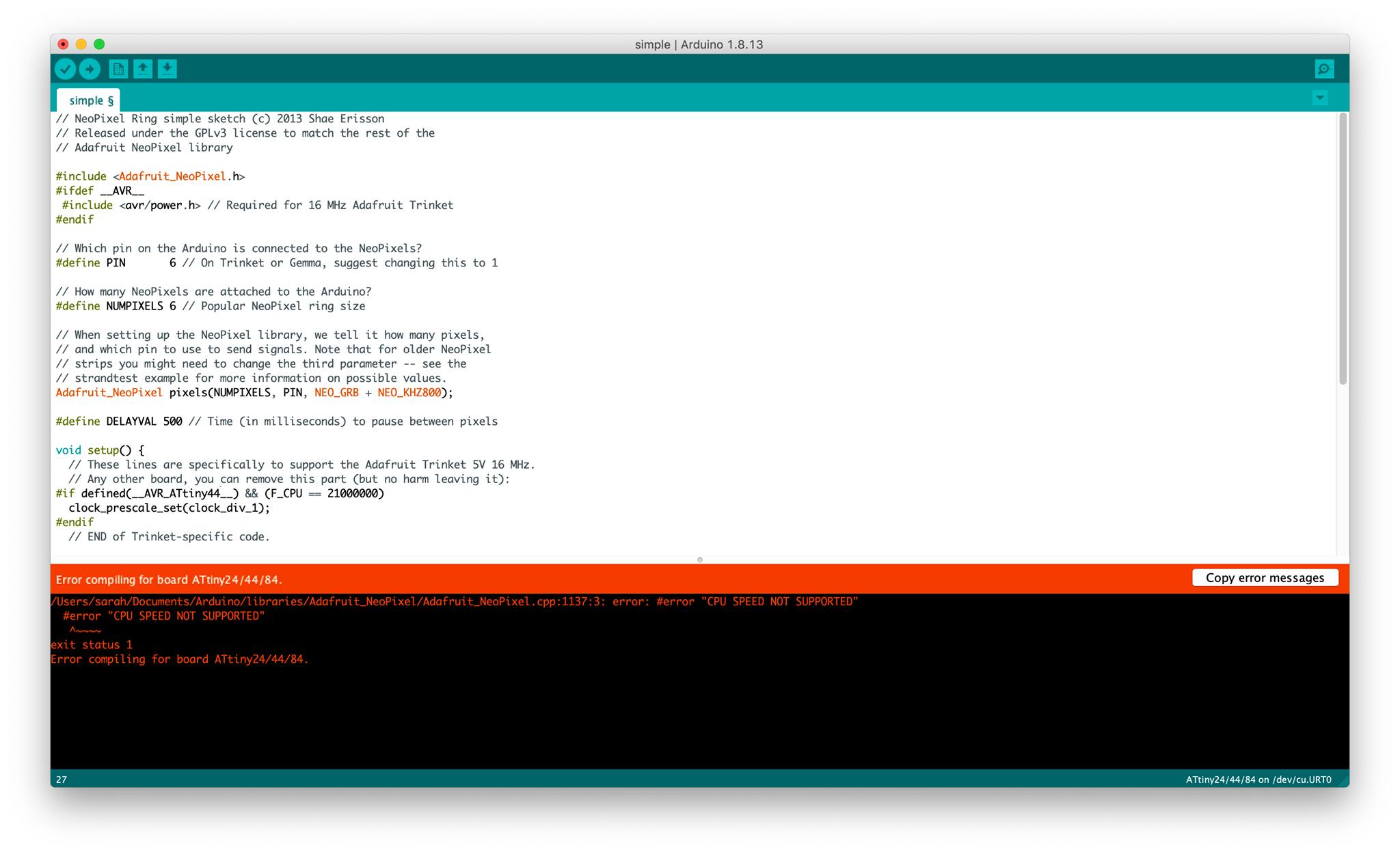
So I searched alot, ALOT, and I found that the fix was simple, all I did was change the Clock in the Tools menu to External 8 MHz and best believe it, it worked.
However, the light was not the brigtest because the board was not supplying enough voltage or current.
I also tried changing the color of the pixels by editing the neopixel line but it didn’t work. I suppose it is because the DIN is not connected to the microcontroller.
Arduino UNO
Like everytime, I then identfied the connections to be made, and I followed the following:
- GND pin on Neopixel to GND on Arduino
- DIN pin on Neopixel to Digital Pin -6 on Arduino
- +5V pin on Neopixel to 5V on Arduino
Then, I connected the microcontroller to my computer using a USB cable, and launched Arduino IDE to upload the code. Following the steps of the embedded programming week, I uploaded the code onto the Arduino UNO and then all was set.
Yet again, the light was very dim.