4. Computer controlled cutting
This week I was introduced to computer controlled cutting: laser machines and vinyl cutters.
Link to group assignment page.
Laser cutting
According to Wikipedia, laser cutting is simply “a technology that uses a laser to slice materials”. It can be used to cut many materials and you can tamper with the prefrences accordingly.
At FabLab UAE, we have the Universal Laser Systems Laser Cutter, and we were first taught to how to use it.
Sketching
To begin, you have to design what you are going to cut. For my part in the group assignment, I decided to cut circles with the settings used on them as it will make it easier to find the settings behind the cut you want. To start I made the basic circle using two different softwares: Fusion 360 and Correll Draw.
After finishing the basic circle design in Fusion 360, I saved my sketch as a .dxf file and opened it in Correll Draw. There, I edited the sketch making the outline red so the machine can recognize it as a cut command, and also made sure it was at hairline thickness. I also added text to test out engraving and I did that by leaving the areas to be engraved in black.

Cutting
I saved the file onto a flash drive and plugged the USB into the monitor connected to the laser cutter to be able to cut it out. I was so anxious about burning the material because I have no idea how to use a fire extinghuisher - ZERO knowledge. I opened the file normally, then Ctrl + P to print, and launched the settings for our beloved PLS6MW.

Because I was cutting cardboard for the group assignment, in the Materials Database tab, I chose Natural > Paper > Cardboard 3mm. However, upon measuring the cardboard, I found that it was around 3.6mm, so I changed the material thickness setting accordingly. I did a few trials with different powers, speed, and frequency, and all those trials are documented below.
| Power | Speed | Frequency | |
|---|---|---|---|
| 65% | 27% | 500 | Did not cut, rather formed sort of an engraving. |
| 100% | 20% | 500 | Managed to cut, but did not achieve the drop-down test. |
| 100% | 24% | 500 | Managed to penetrate through all the layers, yet it was still stuck to the cardboard. |
| 100% | 15% | 500 | My favorite settings! It was a star at the drop-down test. |
When the pieces cut fall out of the material without having to push them out, thats what I call a drop-down.

Measuring the kerf
To measure the Kerf, I cut out a 30x60mm rectangle out of cardboard - since I was responsible of that material - that was divided into 12 equal parts. I used the design pre-made by one of my peers at the lab.
On the first try, I burned the cardboard inside the laser cutter. It was because I forgot to adjust the power settings before cutting - amateur mistake. But I called my peers to help deal with the situation, and I tried again.

Theoretically, each rectangle should have a width of 5mm. And since we have 5 x 12 pieces, the width should amount to 30mm - the width of the whole reactangle in the design. I placed the pieces together and measured the width of the whole rectangle using a digital caliber to find the actual width.

Using the following formula:

Theoretical width - Actual width / Number of pieces
60 - 56.69 / 12 = 0.275
I found that the kerf of the laser beam for the settings: was 0.275mm, and I had to account for that during designing for my individual assignment.
Individual Assignment: Design, lasercut, and document a parametric press-fit construction kit, which can be assembled in multiple ways. Account for the lasercutter kerf.
Press-fit construction kit
For my individual assignment, I was inspired by the 3D puzzles I would build with my dad when I was young. They were so much fun and I wanted to utilize this opportunity to do something similar. Hence, I decided that upon building my kit, it would end up looking like a chandelier.
I first started designing my kit in Fusion 360, and it took alot of time - ALOT!
I started my sketching it in 2D; however, on the course of events, you will notice that I have changed to 3D as one piece gave me so much trouble.
I started by drawing 3 circles on the top plane. Then, I set the diameters as I saw fit. I set the diameter of the middle circle as a parameter, found a relationship between those diameters, and then changed their dimensions to be in relation to the parameter - making it parametric.
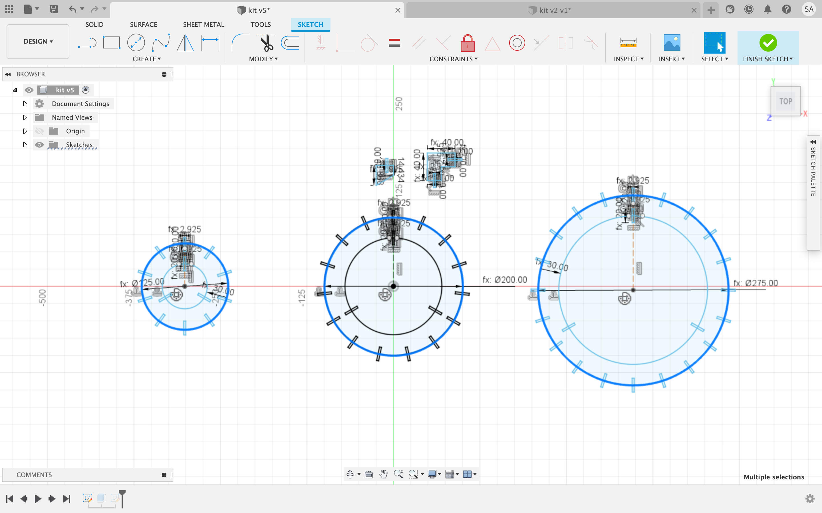
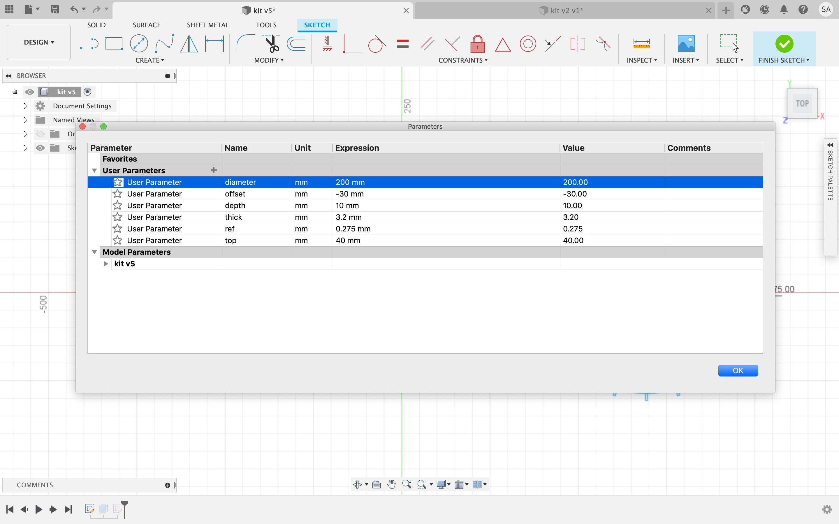
I then drew circles inside the aforementioned circles, that will be cut out later as I wanted the middle to be hollow, using the offset tool. I set the offset as a parameter of 30mm so the piece will remain sturdy even after some of the area will be cut off for the slots.

Next, I made the slots. I did this by sketching a center rectangle and then adjusting the length to be how deep I wanted it to go into the cardboard multiplied by 2 (because i have to account for the other half that will be in the other pieces). I decided I wanted to go with 1cm so I added “depth” as a parameter of 10mm.(highlighted in blue)

Now that the length is set to 20mm (depth*2), I had to adjust the width. The width was not as flexible as the length it had to be the thickness of the material - the kerf. So, 3mm - 0.275. I set “thickness” and “ref” as parameters, as each material will have a different thickness, making the kit more user-friendly.

To avoid repeating the process of making the slots numerous times around the circle, I used the circular pattern tool under the create tab to do that for me. I selected the 4 sides of the slots, and then selected the centre point of the circle, and choose different quantities for each circle.

Now that we have the three circles done, I had to do the ‘light’ pieces of the chandelier. I sketched connectors using the line tool to extend from the side of the circle down with a slot to plug the light in. I set the longer sides of the piece to a parameter ‘top’ of 40mm, and the shorter ones to ‘top’/2 (20mm). Then I added the slots similar to the previous steps: create a rectangle then set the dimensions to the previously set parameters.


For the ‘light’ piece, I sketched a circumscribed polygon and using the trim tool, got rid of most of the sides till I got the final shape. I set the sides to a fixed length that I saw suitable, added the slots just like the previous steps, and I was done.

However, I was not really done. I had to connect the three circles to stand somehow, hence forming a chandelier, and this is where the trouble kicked in. So far, everything was smooth sailing, but the rod connecting the whole piece was a mischeif. Here is where the 3D part came in. I reskecthed the circles on a new document in Fusion 360 with no slots. This time I sketched them inside each other, to have one central point and so that when extruding, they will align over each other. Then I extruded them to the ‘thickness’ dimension, and using the inspect tool measured from the point inside the circles to where the slots are to be places.


Using that, I created a triangle with a random width of 50mm and out the measurment I found as the length. Spoiler Alert: It did not work. I knew, I had to get a slope somehow, and I had trouble with that. So, that kit was discarded, but the other pieces worked just fine. The mission now was to solve the question: How to make the rod? After advising with one of my instructors, I was told that I could first design the whole piece in 3D and then extract the faces of the pieces as sketches. I built on the 3D sketches and this time i drew lines just like the previous step, and then offset them to a width of 15mm. Using the combine tool, I selected the circle as a target body, and the rod as the tool body. Then, I changed the mode to “cut” and that automatically created slots in the circle. I did the same thing again but switched the circle to the tool body, and the rod as the target body. This created slots in the rod too. All I had to do now was circular pattern the slots around the circle, and do the same to the rod.
I saved the pieces as DXF files and then opened them in Correll Draw. There I changed the outline color to red, and sent it for cutting.


This is how the final project looked:


Vinyl Cutting
Individual Assignment: cut something on the vinylcutter.

Designing
For Vinyl Cutting, I cut out a sticker of a geometric bear. I got the photo off of Google and pasted it into Correll Draw.

Then, I converted it to bitmap so I can change the raster photo into a vector, otherwise the vinyl cutter will have no paths to follow when cutting.

Then I quick traced it using the quick trace option under the trace menu, and checked its edges to see whether it was sufficient or needed another run.

I saved the file onto a flash drive and plugged it into the computer connected to the cutter. I chose to have it in gold so i changed the roll to a gold one.


Cutting
Cutting was pretty simple. Using the arrows on the cutter, I moved the blade to an empty place on the roll. The I set it at the origin by pressing the ‘origin’ button.

I opened the Correll Draw file, and pressed the printer’s plugin to load it into the software.

There I changed some cut settings: I had the cutting area (width) come from the machine itself by pressing the “get from machine” button, and changed the length to 100mm so that the roll wouldn’t all roll out the machine when its done cutting.

I pressed ok, and sent it off to cut.

On the first try, I didn’t use a sufficient amount of force, so the vinyl wasn’t completely cut; therefore, I couldn’t peel off the sticker from the backing.

I performed tests to find out what was the required force to cut the vinyl. I did this by moving the blade to an empty area on the sheet using the arrows, and then pressing the test button.

I tried various forces until I was able to extract the seperate pieces of the sticker without tampering with the others. I ended up going up to 160gf.

I tried cutting the design again, and this time it worked!

Post-cutting
I grabbed an exacto knife and a cutting board and started carefully peeling off the areas I didn’t want.

After that was done I cut off a piece of adhesive film and put it on the design and pressed out all the air bubbles using a piece of plastic.


After that was done, I peeled the sticker off the backing with its front face stuck to the adhesive film.

The sticker was ready, and I could place it anywhere, so I placed it beside my trackpad on my laptop.


I removed the adhesive from the top of the sticker and I was done!
