5. Electronics production
This week I worked on producing electronics using various techniques.
Link to group assignment page.
PCB production using milling
Using milling to print your circuit board basically means removing some areas off a copper sheet (or PCB material) to outline the traces, pads, and structures. You usually start off with designing the circuit board digitally using softwares such as Eagle; however, for this assignment I used a pre-designed outline and trace png file provided by FabAcademy.
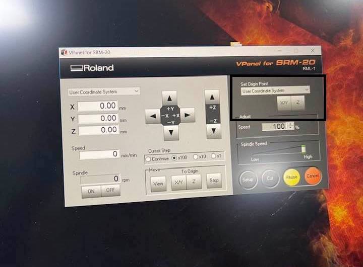
PCB milling is done using CNC milling machines, also reffered to as computer numerical control milling. At FabLab UAE, we have the Roland MonoFab SRM-20.
The machine can move over three axises: x, y, and z. The x moves left and right, the y forward and back, and the z up and down.
Individual Assignment: Building the FabTinyISP
Step One: Find or design your circuit board
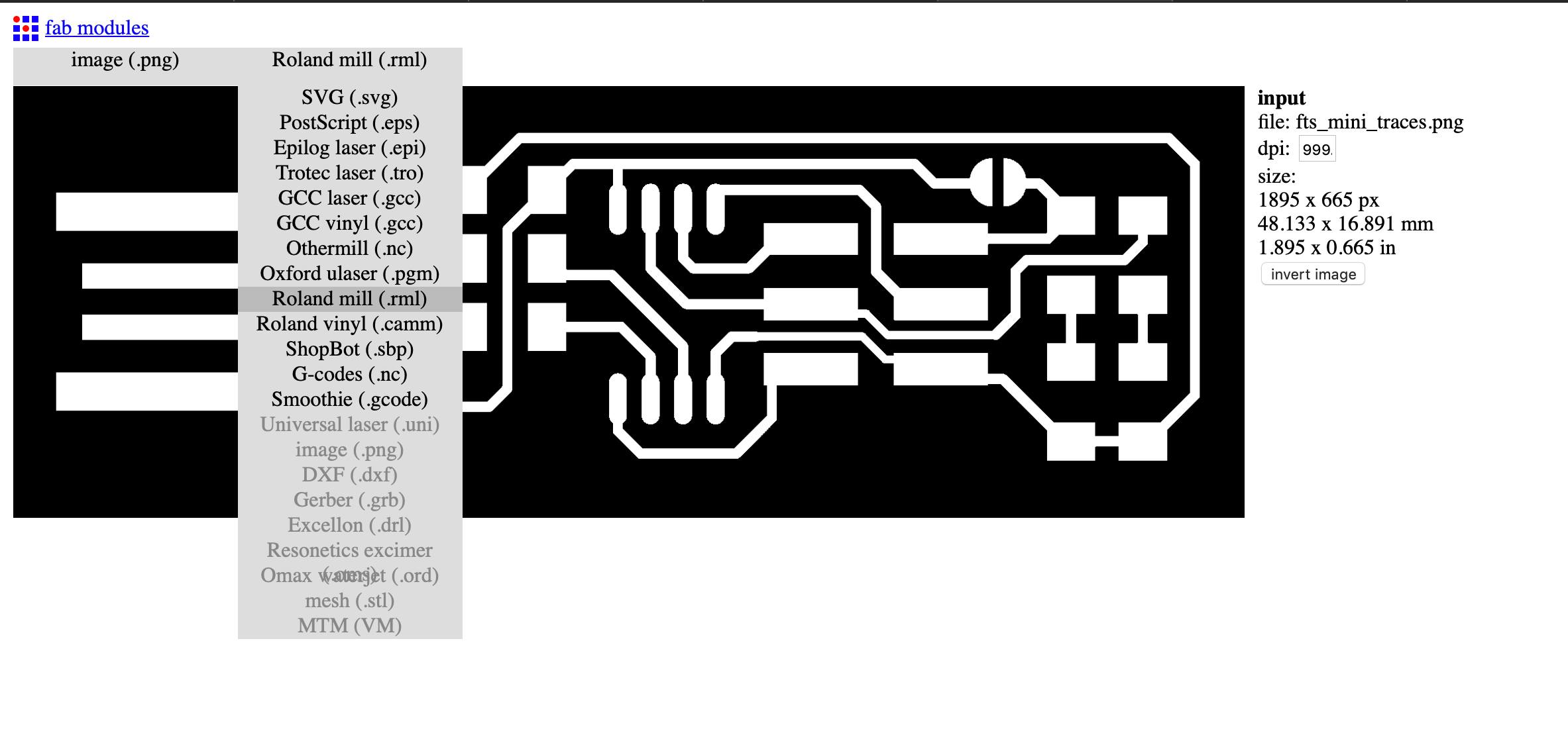
As mentioned earlier, for this assignment, we are to use the traces and outline files provided by FabAcademy to build the FabTinyISP. I downloaded the following as png from the FabTinyISP page:
Traces
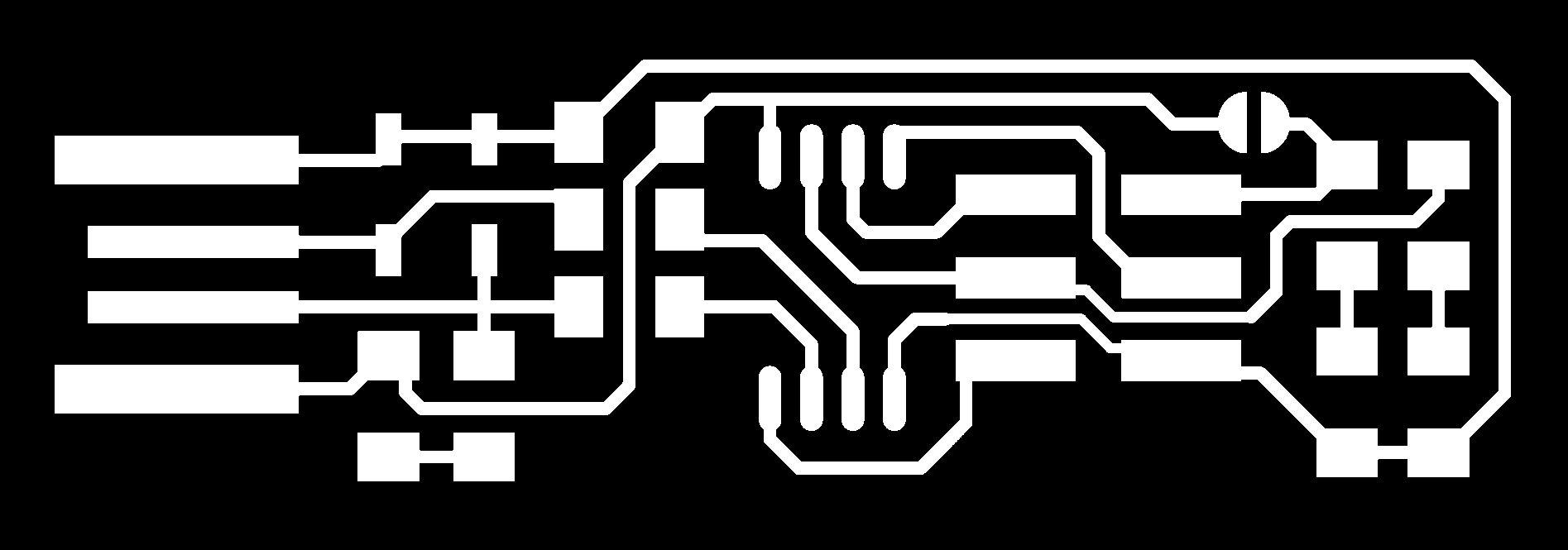
Outline

Step Two: Turn it into paths
Unlike you, the machine isn’t able to distinguish where it should remove copper from when milling; hence, we use fab modules to outline the paths for the CNC machine.
-
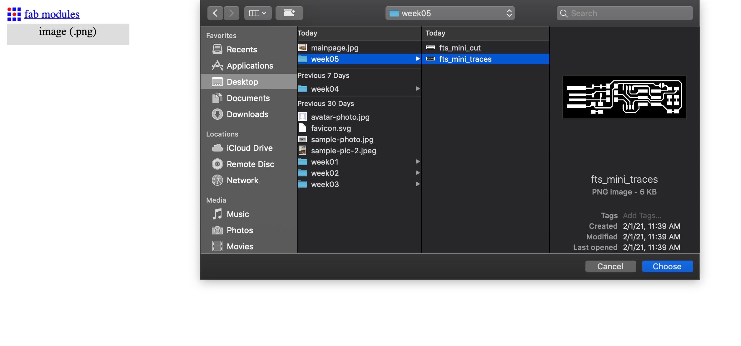
Open fab modules and open your traces file into input format> image (.png).
-
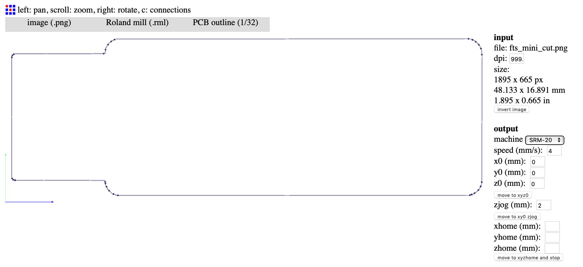
For the output format, I chose Roland mill (.rml) because it is the supported format for the local CNC machine.
-
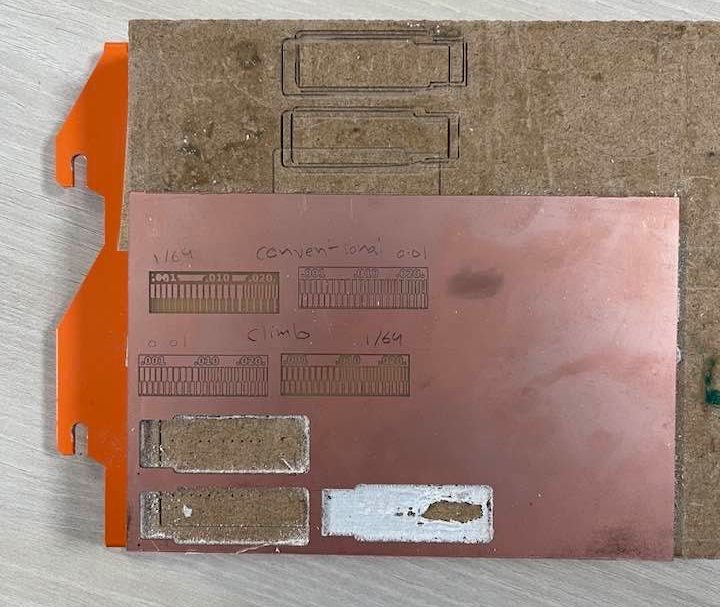
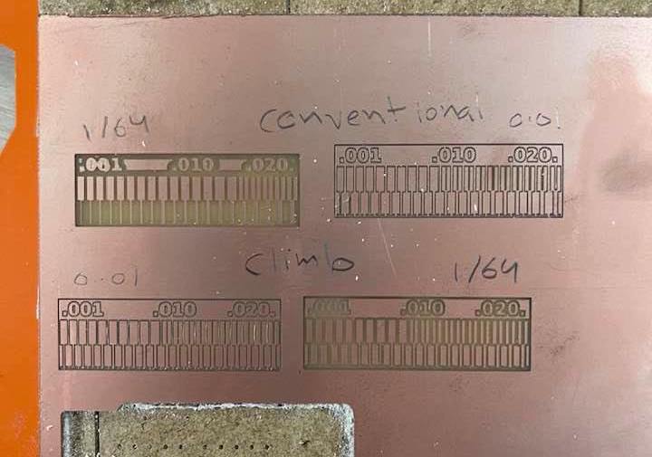
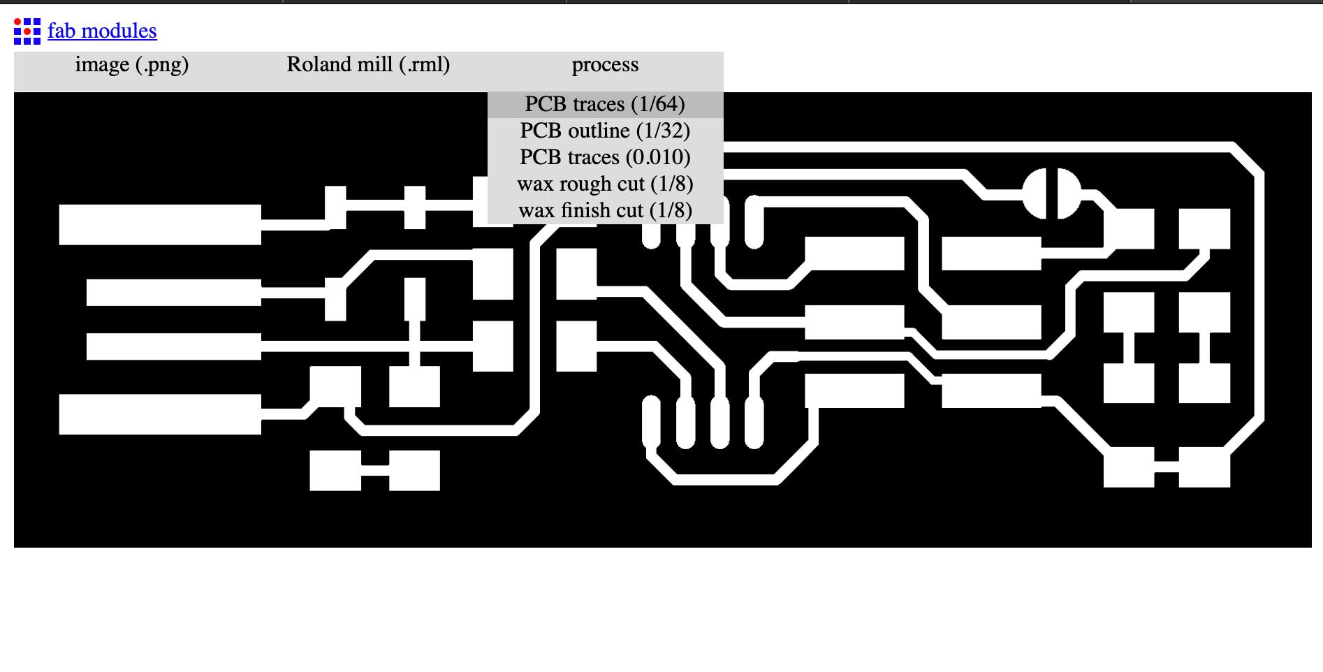
For process, I chose PCB traces (1/64), because I was doing this for milling the traces. (1/64) stands for the mill bit’s thickness. Different thicknesses are used for different things, for traces, we usually opt for (1/64).
-
For the settings portion towards the right of the image, I changed them to be as the following:
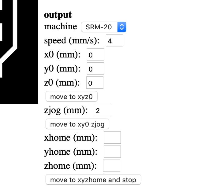
I only set the machine to SRM-20 and the x0, y0, and z0, to 0. The speed and zjog was automatically done for me after setting the machine option to SRM-20.
-
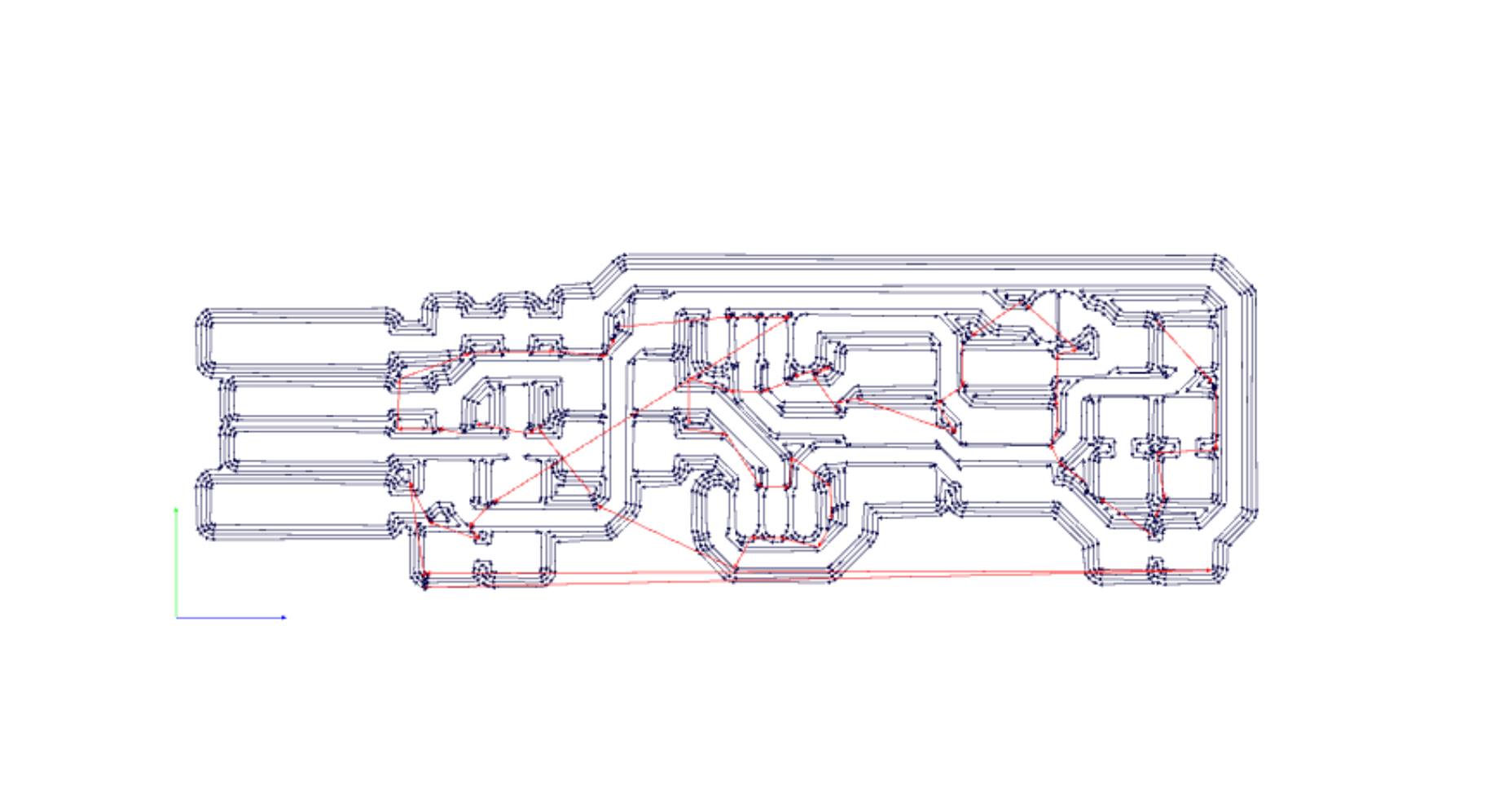
Then, I pressed on calculate under the “process” section of the settings, and then save, and I was done.
-
I repeated the same process for the outline; however, for process I chose PCB outline (1/32) instead.
(1/64) Mill Bit
(1/32) Mill Bit
Step Three: The preparation
-
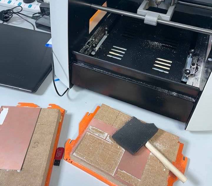
First, prepare! Tape down your PCB material, in my case this copper looking sheet also known as FR1, to the sacrificial board which is a piece of wood pre-secured into the CNC machine. Also, make sure both the piece of wood or acryl and PCB material are clean and no dust is in the way.
-
Set the origin to zeros for your X/Y by using the arrows on the machine. A good place to set it is in the bottom left corner of a new sheet, or the next empty space on a used one.
-
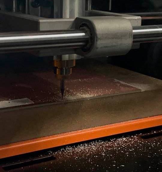
For the Z, and extra step will be taken. Place the Z a few milimeters above the board. Then we will have to manually adjust it to sit perfectly on top of the board. This extra step is because of how sensitive the mill bit and how prone it is to break. So, to ensure that doesn’t happen, we do it manually by unscrewing it loose using an allen wrench.
-
After I had my X/Y/Z on the perfect spot, I set it as the origin points by pressing the set origin point button.
Step Four: Cut, cut, cut!
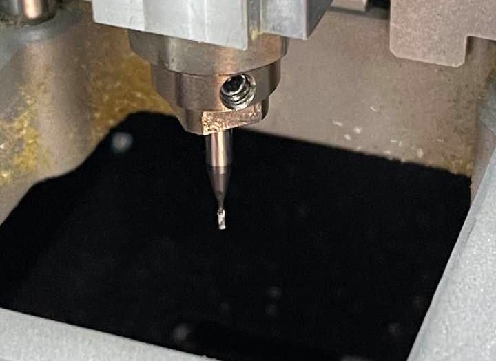
- The last step is to cut, or basically perform the milling. I did this by clicking on “cut”, then adding the file to the machine, and then pressing on “output”. I first did the traces:
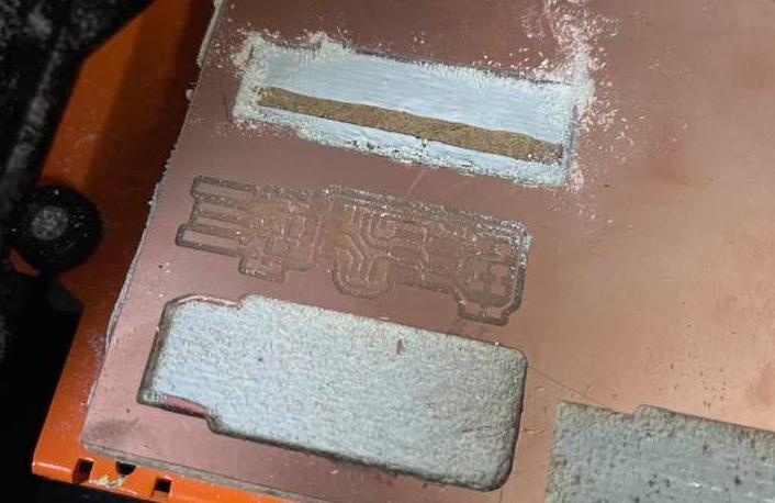
- I repeated the same process for the outline, but I had to change the mill bit to (1/32) first. So, I used the allen wrench, removed the (1/64) mill bit, put the (1/32) in, and screwed it back in. I didn’t change any of the X/Y setting, but I had to redo the Z part, and set the origin again.
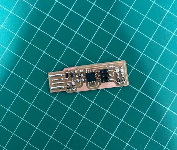
PCB using Milling
Soldering
After milling your PCB, you will have to add its components. Since we are using the surface mounting technique, we dont need to drill any holes in the PCB.
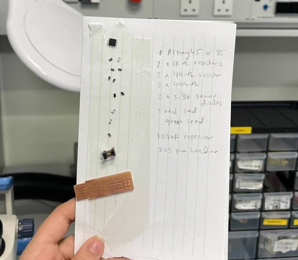
- First, go shopping for your components. Gather all your components into one place to make soldering less hectic. Because the components are very tiny, adding double-sided tape to a piece of paper and then placing them on to it will make it much easier. I also labeled the parts on the side just to avoid all confusion
- Then using the solderer and the hot iron I began soldering. There isn’t a way sufficient enough to explain soldering using words, but I discovered there isn’t one definite way to solder.
-
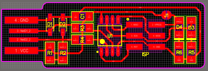
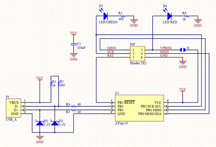
I made sure to display the schematic and board view of the FabTinyISP to know where the components should be placed. They should also be placed in the correct orientation (According to Fab Tutorials):
-
The line on the zener diodes indicates the cathode side.
-
Thick lines and dots on PCB drawings mark the LED cathodes.
-
The dot on the corner of the ATtiny45 marks pin 1.
- After soldering, I was ready for programming.
Programming
-
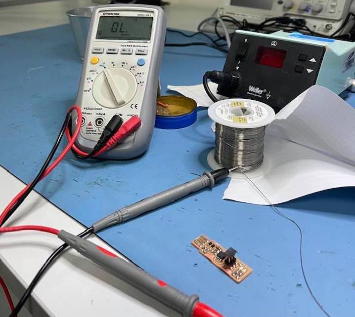
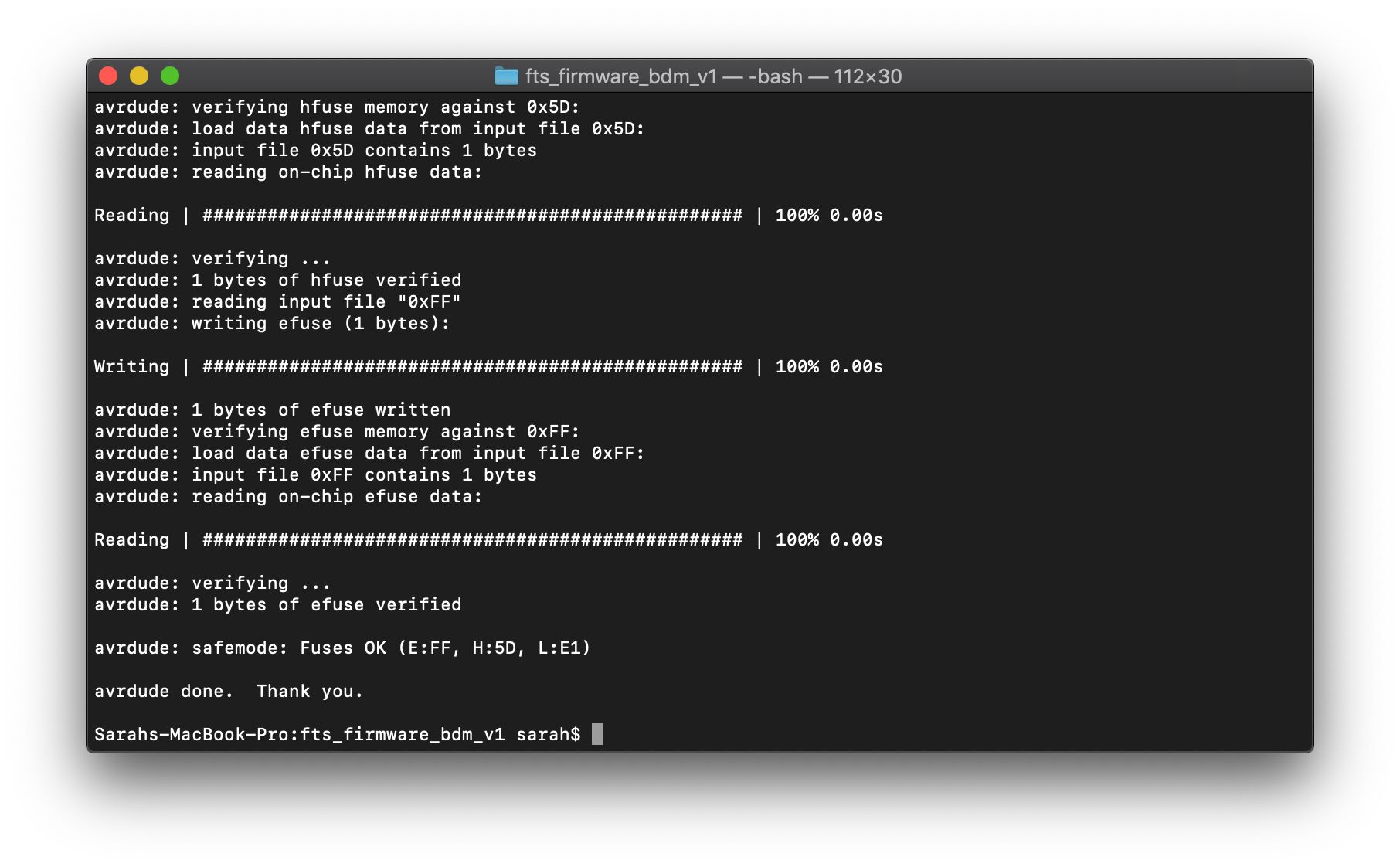
Before programming, I made sure to check for short circuits using a multimeter. I had to make sure there were none, and there wasnt which was really good news.
-
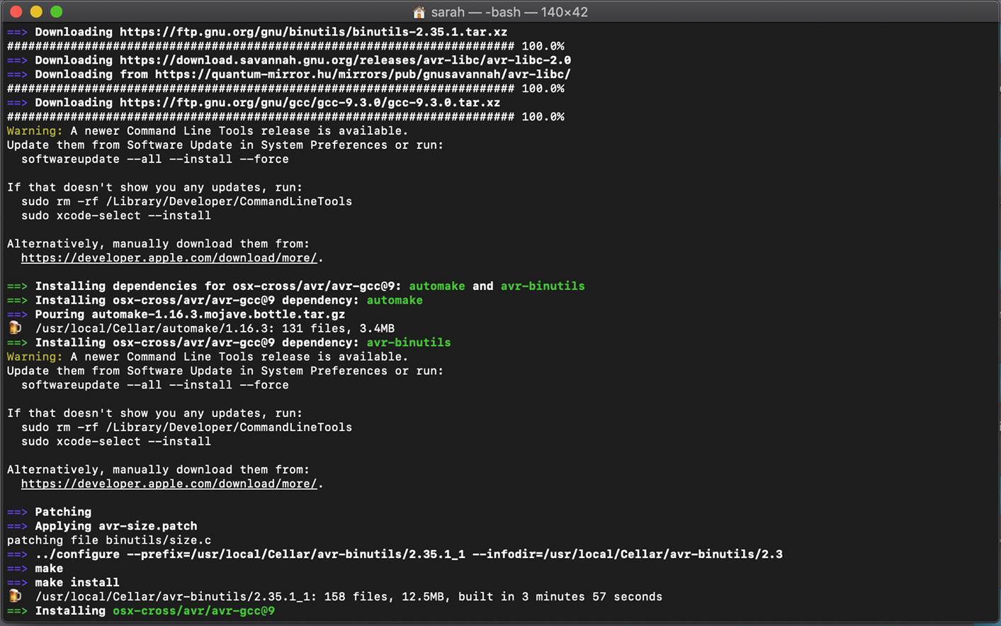
Programming was relatively easy; however, I had faced some issues. First I ran the following commands in my terminal to install the required softwares for Mac (I got the steps below from Fatima Al Hashimi, a former FabAcademy student’s page:
brew tap osx-cross/avr
brew install binutils
brew install gcc
brew tap osx-cross/avr && brew install avr-gcc
brew install avrdude
-
To ensure that the correct versions were installed, I restarted my terminal by quitting it, and relaunching it and ran
avr-gcc --versionandMake -v. -
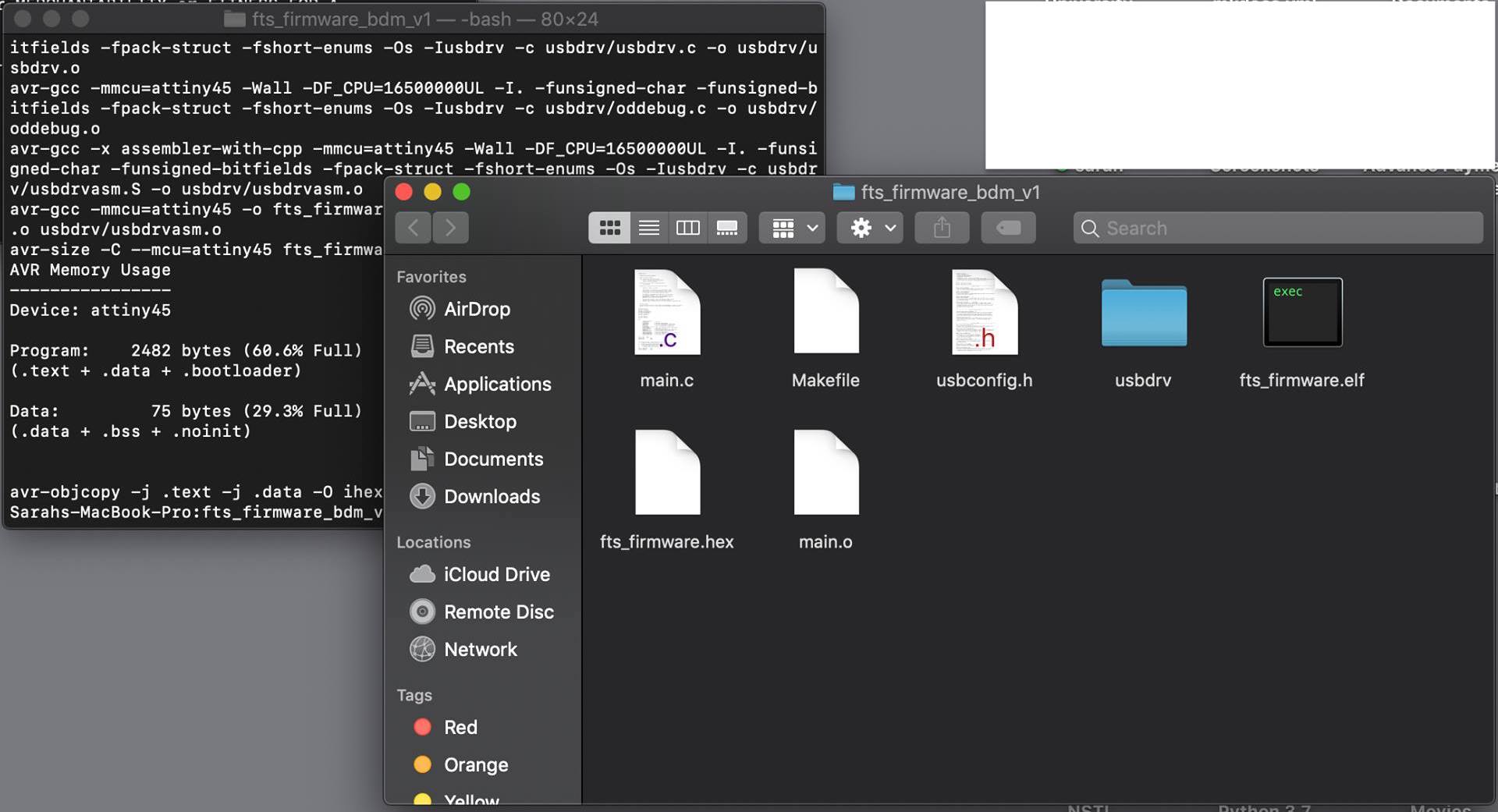
After installing the softwares in the first step, I had a file named fts_firmware_bdm_v1 on my desktop. I cd into that file and opened a terminal there and ran
make. -
After running it, I got a file within it named
fts_firmware.hex.
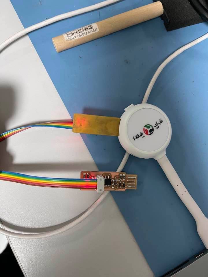
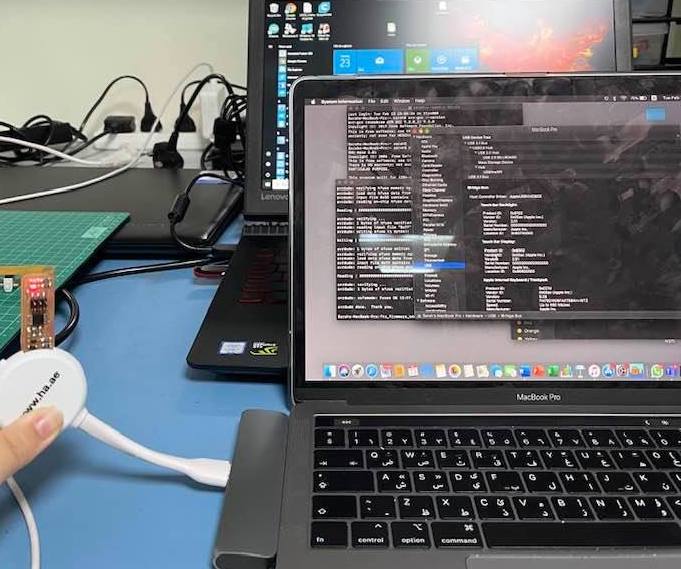
- It was time to connect the FabtinyISP into my computer to activate it. I had to use a hub since the FabTinyISP only works with USB 2 and my laptop has a USB 3 port. To connect the programmer, I used a ribbon cable and a connector that I added to the cable. With a previously programmed FabTinyISP plugged into the hub, and mine on the other side of the ribbon cable, I started programming it.
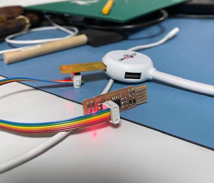
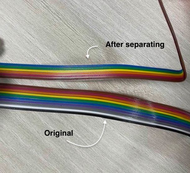
The steps to prepare the ribbon cable are as follows:
- Seperate a cluster of 6 wires since the header in the FabTinyIsp has 6 openings, and then cut it to a desired length - not too long, not too short though.
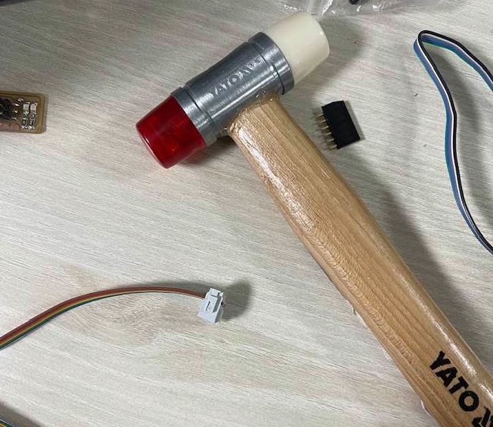
- I grabbed a female 3 x 2 connector, placed the wires through its opening, and using a hammer I secured it shut.
- To ensure, you are connecting both programmers correctly, a helpful tip I learned was to fold the wires in half first and then making sure the same colored wire is connected to the same places in both programmers.
- The next step is to activate the programmer, to do so I ran
make flashin the terminal, and it completed successfully. Next I ranmake fusesand it ran very quickly.
- I was supposed to be done, and I only had one more thing to do. However, when I plugged in my programmer to check whether my Mac recognized it, it didnt. Upon further inspection I realized that I had soldered some wrong components, and the diodes in a wrong orientation. I had to remove them, and place the correct ones instead. I was told it was very weird that
make fusesran successfully, and did not burn my programmer with this mistake in place.
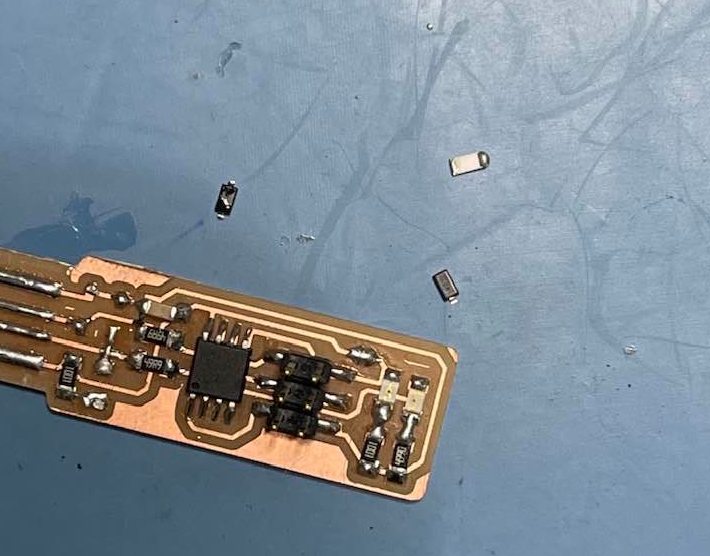
- Using a heat gun, I removed the components, soldered the correct ones using the iron, and repeated the steps starting from
make flash.
- This time, my latop successfully recognized the FabTinyIsp, and I was ready to burn the reset fuse using
make rstdisbl.
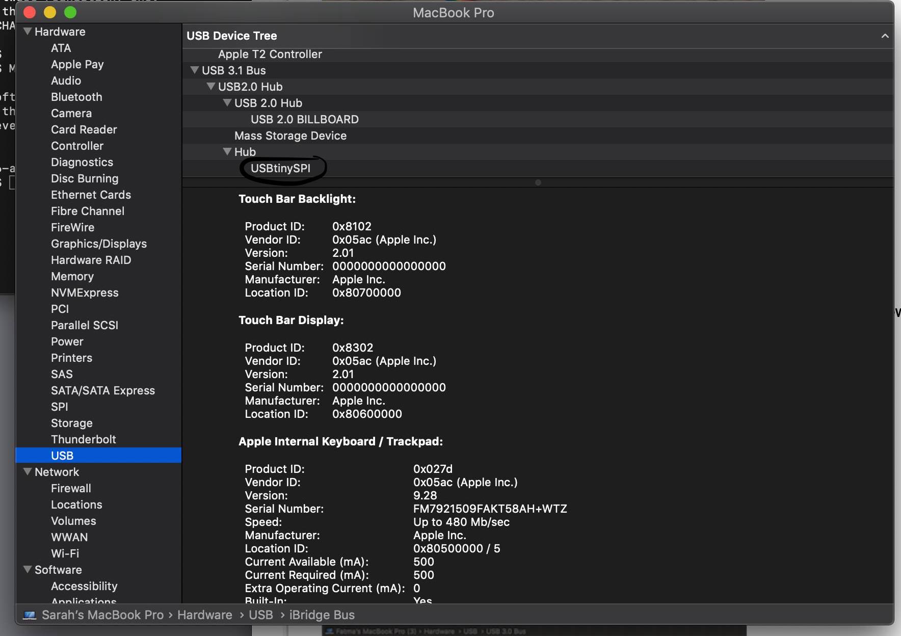
- After that step, I had completed my FabTinyISP!
Utilizing the FabTinyISP
Group Assignment