9. Embedded programming⚓︎
-
- Compare the performance and development workflows for different microcontroller families.
- Document your work (in a group or individually).
-
Individual assignment
- Read the datasheet for the microcontroller you are programming.
- Program the board you have made to do something, with as many different programming languages and programming environments as possible.
-
Learning outcomes
- Identify relevant information in a microcontroller datasheet.
- Implement programming protocols.
-
Have you?
- Linked to the group assignment page.
- Documented what you learned from reading a microcontroller datasheet.
- Programmed your board.
- Described the programming process/es you used.
- Included your source code.
- Included a short ‘hero video’ of your board.
Hello.ftdi.45.Sergio⚓︎
Two weeks ago, in the Electronic Design assignment I designed a board based on Neil’s hello.ftdi.45, with a led and a button added to the two remaining free pins of the ATtiny45. Once the board was designed, milled, soldered and tested I tried some basic programs using the FabISP programmer. This process is documented in Electronic Production week.
In that case I used Arduino and the Blink and Button program that this IDE has by default, to check if everything was working correctly. This week my intention is to use the code base of these programs to test different functions and possibilities, both code and hardware.

Programming⚓︎
When trying to reload the code to the board, I have assumed that it will be able to communicate directly with the PC and Arduino IDE without an external programmer like FabISP, since it has been programmed before. My instructor Pablo has explained to me that it doesn’t work like that. For the processor to be able to communicate directly or understand the communication it establishes with the IDE, it needs to have a preloaded code, but not any execution code but the bootloader. In a nutshells, this code is responsible of “transcribing” the commands to the chip so that it can execute them. For a better understanding on how this work, you can check the bootloader link.


Pwm pins⚓︎
I have tried to use this board to make PWM on the integrated led, since it is something that I had not done before with programming. I’ve made this simple program to simulate the PWM and I have used analogWrite function to be able to make it work.
int led = 3;           // the PWM pin the LED is attached to
int brightness = 0;    // how bright the LED is
int fadeAmount = 10;    // how many points to fade the LED by

void setup(){
    pinMode(led, OUTPUT);
}

void loop(){  // the loop routine runs over and over again forever:

    analogWrite(led, brightness);
    brightness = brightness + fadeAmount;   //change the brightness for next time through the loop
    if (brightness <= 0 || brightness >= 255)   //reverses the direction of the fading at the end of the fade
        fadeAmount = -fadeAmount;
    delay(30);  //wait for 30 milliseconds to see the dimming effect
}
When sending the code, the led does not respond to the PWM sequence. This can be for several reasons, although I mainly highlight two: the code is wrong or the led pin is not PWM (but I was pretty sure I used the PWM pin for the led). After reviewing the code with my instructor and using the Arduino reference, we have decided to test the PWM in other pin and use an external led and dupont connections to check if we could produce that effect. As you could see in the video below, we could produce the PWM in the so have to review why a pin which is labeled as PWM in the microcontroller datasheet, it really isn’t.
Datasheet⚓︎
I came back to Electronics Design week, when this board was designed, to check the schematic. As you can clearly see, the led is connected to pin number 2, also labeled as PB3.


This is what the datasheet says about the PB3 pin:
Port B, Bit 3 – XTAL1/CLKI/ADC3/OC1B/PCINT3:
- XTAL1: Chip Clock Oscillator pin 1. Used for all chip clock sources except internal calibrateble RC oscillator. When used as a clock pin, the pin can not be used as an I/O pin.
- CLKI: Clock Input from an external clock source, see “External Clock” on page 26.
- ADC3: Analog to Digital Converter, Channel 3.
- OC1B: Inverted Output Compare Match output: The PB3 pin can serve as an external output for the Timer/Counter1 Compare Match B when configured as an output (DDB3 set). The OC1B pin is also the inverted output pin for the PWM mode timer function.
- PCINT3: Pin Change Interrupt source 3.
Hello.t412.3.Sergio⚓︎
After having tested different codes with the ATtiny45 I have decided to make the jump to the new ATtiny412 microcontrollers. Although it is not a different architecture, the toolchain needed to program it is, and since these chips are the current ones I want to have a good handle on them for future applications in the next weeks. Besides, I’ve thought of a little game to make with some lines of code and a board with a button and several leds, so the ATtiny45 didn’t work for me as it doesn’t have more pins available and it has less capacity.

| Specifications | ATtiny412 |
|---|---|
| Flash memory | 4096 bytes |
| RAM | 256 bytes |
| EEPROM | 128 bytes |
| PWM Channels | 4 |
| Interfaces | UART, SPI, I2C |
| Clock options | Internal 20/16/10/8/5/4/1 MHz |

My idea is to create a board with several leds placed in line, that flash quickly from one to another and that you have to press the button when one of the indicated leds is on. I have started from the hello.t412.3 board adding the 3 more necessary leds and the button. The process has been identical to the one I followed in the Electronic Design assignment a couple of weeks ago.
Design⚓︎
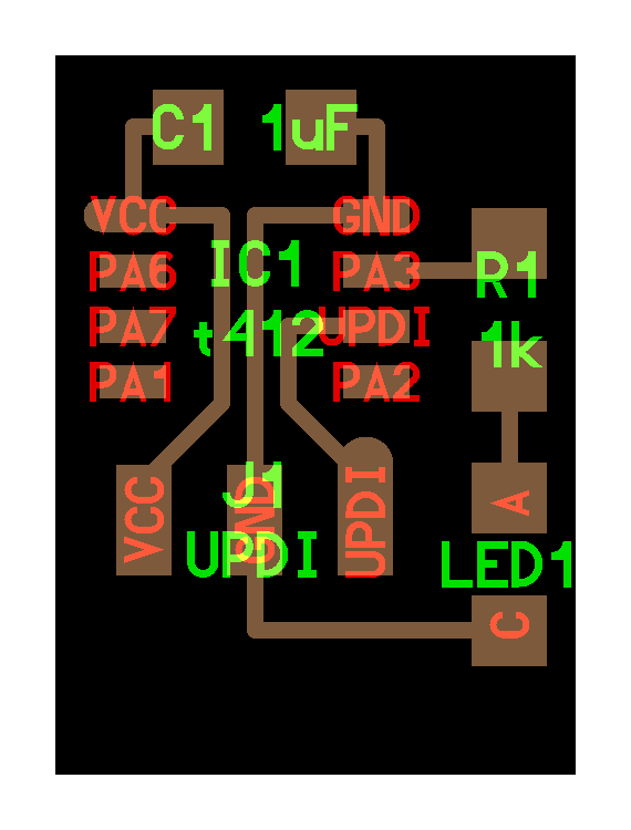
Some problems I have encountered are that the ATtiny412 does not have a footprint in the fab library or in any of the default Eagle libraries, so I have had to resort to the alumni documentation, finding several web pages where there are a lot of footprints of any component. Here I attach the ATtiny412 footprint that SnapEDA has, although in my case I have used the one from this fellow from Oulu, Noora Nyberg.


| Component | Librarie name | Quantity |
|---|---|---|
| Microcontroller | ATTINY412-SSF | 1 |
| UPDI connector | SW_SPDTSWITCH | 1 |
| Capacitor | CAP_UNPOLARIZEDFAB | 1 |
| Button | SW_SWITCH_TACTILE_6MM6MM_SWITCH | 1 |
| Resistance | R1206FAB | 5 |
| Led | LEDFAB1206 | 4 |
After labeling all the routes to avoid missing a connection, as it happened with the ATtiny45 which I had to Frankestein, I have routedthe boards as clean as possible trying to avoid 0 ohmios resistances to jump traces.


I think it came out pretty well, also it ended up being very compact. Looking back from now to the week where we started with electronics, it looks like a milestone for me to have made this board straight forward without any help. I guess I’m learning!
Also I tried to add some customization to match the mechanic of the game, labeling which is the led you have to get the press correct on, the led which marks if you have made the press in the correct timming and the button.

Milling⚓︎
As always, I tried to check the mill was making the paths I wanted using the online ModsCE tool. It looks like everthing is milled correctly and the DRC from Eagle worked fine!

Then used FabModules with the Mac connected to the Modela here at the Lab to get my borad out. Traces were made with 1/64 mill and exterior with 1/32 mill like always. As with the Eagle workflow, milling is getting smoother too. I love this part of the learning curve.

After some vacuum cleaning and fixing some edges the board was smooth and shiny. I did some washing with the soap sponge to remove the smallest imperfections and get rid of the grease, but I think I went a bit hard on it.


Soldering⚓︎
First of all Nuria helped me out taking all the components I needed for the “Fab Electronic Shop”. I am used to this method of sticking them to a paper to get a better inventory of what I will use and solder.

| Component | Quantity |
|---|---|
| ATtiny 412 | 1 |
| UPDI connector | 1 |
| Capacitor 1uF | 1 |
| Button | 1 |
| Resistance 0.5K | 4 |
| Resistance 10K | 1 |
| Led | 4 |
It’s solder time. I’ve noticed that I have left a bit less space than ideal for an easy solder, but since I have more pratice I made a cleanest like job. The hero shot of the board looks a bit reflective so it feels like there are imperfections, which there are, but not as it looks there.


Timelapse of the process:
Testing⚓︎
Continuity between traces and components was fine and soldering looks solid. Since I need to used the UPDI to FTDI I made during week04 I wanted to make sure the pins were matching it’s correct connection. My college and instructor Adrian uses paint but I am a bit more from the razer side, so I made this cuts. Despite what it may seem, I am a very peaceful boy.


Programming⚓︎
Now onto the real work for this week. I have to say I was expecting a challanging proccess to program this board since Adrian told me his experience last year was a bit rough, but he has discovered me that at the beginning of January 2021, the programming method for the new AVR microcontrollers was updated. By updating megaTinyCore you can now upload directly from the Arduino IDE. Eternal love to Adrian for the info and his tutorial.
From Arduino, in the preferences tab we will add the URL to load the Arduino IDE with other cards or microcontrollers as we did for the ATtiny45. Spence Konde has a guided tutorial for this proccess but I will also document mine. The boards manager URL is:
http://drazzy.com/package_drazzy.com_index.json


In tools, we will look for the boards and the boards manager. We will search for “megaTinyCore by Spence Konde” and install it. I founded it at the bottom of the list. Also make sure to select the last version.


In this screenshot I show all the parameters and configuration selected to program the ATtiny412, again taking Adrian’s tutorial as a reference.

I tested the settings by uploading a small blink program to the board and worked fine!

Then I have decided to try if the leds work correctly and the timing of the clock is matching the delay specified in the code and it worked fine. Attached below you can find the code itself and a demostration video.
void setup()
{
  pinMode(1, OUTPUT);
  pinMode(2, OUTPUT);
  pinMode(3, OUTPUT);
  pinMode(4, OUTPUT);
}

void loop()
{
  digitalWrite(1, HIGH);
  delay(200);
  digitalWrite(1, LOW);
  digitalWrite(2, HIGH);
  delay(200);
  digitalWrite(2, LOW);
  digitalWrite(3, HIGH);
  delay(200);
  digitalWrite(3, LOW);
  digitalWrite(4, HIGH);
  delay(200);
  digitalWrite(4, LOW);
}
Press&Play⚓︎
Now that we’ve checked that everything works, it’s time to try programming the board to recreate our game! In short, it consists of the three red LEDs flashing in a very fast cycle, with the aim of trying to press the button at the exact moment when the red LED indicated with an arrow on the board is flashing. If we succeed, the green light will light up, in case of failure, the 3 red leds will flash.
I have made several iterations of the code, first trying to do it in a precarious way with direct commands and later using variables and integrating processes within processes to get the closest to the desired result. Even so, there are still several errors. The first one is that the orders must coincide in time but the leds cannot be used as inputs, only outputs, because we cannot read the state of the led, we have to rely on knowing the order we are sending at each moment. The second thing is that for reasons I don’t know yet the hit function doesn’t work, and after several times changing the variables of the result to obtain different outputs the result is quite random. Also the timing is a matter of milliseconds and it is a parameter over which I really don’t know how much control I am having in terms of execution orders.
void setup()
{
  pinMode(0, INPUT); // Pin 2. PA06. Button.
  pinMode(1, OUTPUT); // Pin 3. PA7. Red led to match with the button.
  pinMode(2, OUTPUT); // Pin 4. PA1. Red led.
  pinMode(3, OUTPUT); // Pin 5. PA2. Red led.
  pinMode(4, OUTPUT); // Pin 7. PA3. Green led which ligths up when you hit it right.
}

void loop()
{
  int RESULTADO = 2;
  int VELOCIDAD = 100;  //Game speed

  //Led sequence of the game
  digitalWrite(1, HIGH);
  delay(VELOCIDAD);
  digitalWrite(1, LOW);
  digitalWrite(2, HIGH);
  delay(VELOCIDAD);
  digitalWrite(2, LOW);
  digitalWrite(3, HIGH);
  delay(VELOCIDAD);
  digitalWrite(3, LOW);

  while (digitalWrite(1, HIGH))   //If third red led is on
  {
    if (digitalRead(0) == HIGH)   //If the button is pressed
      RESULTADO = 1;
    else
      RESULTADO = 0;
  }
  while (digitalWrite(2, HIGH))   //If third red led is on
  {
    if (digitalRead(0) == HIGH)   //If the button is pressed
      RESULTADO = 0;
    else
      RESULTADO = 2;
  }
  while (digitalWrite(3, HIGH))   //If third red led is on
  {
    if (digitalRead(0) == HIGH)   //If the button is pressed
      RESULTADO = 0;
    else
      RESULTADO = 2;
  }

  if (RESULTADO == 1)   //If you have hitted it right
  {
    for (int x = 0; x < 4; x++)
    {
      digitalWrite(4, HIGH);
      delay(200);
      digitalWrite(4, LOW);
      delay(100);
    }
  }
  if (RESULTADO == 0)   //If you have hitted it wrong
  {
    for (int x = 0; x < 4; x++)
    {
      digitalWrite(1, HIGH);
      digitalWrite(2, HIGH);
      digitalWrite(3, HIGH);
      delay (200);
      digitalWrite(1, LOW);
      digitalWrite(2, LOW);
      digitalWrite(3, LOW);
      delay (100);
    }
  }
}
Here is an example of some of the iterations I’ve made. The last one is the most accurate but it seems impossible to hit it right, so you just can fail. As in life. I guess is a philosophical board! 

Update⚓︎
The truth is that I had a lot of fun trying to program the game that I had created with this board, and since I was left with a not entirely correct version, I have taken a while from other weeks to improve the code. Using Boolean variables to store the status of the LEDs fixes everything. Now it works perfect!
int BUTTON = 0;  // Pin 0. PA06. Button.
int LEDR1 = 1;   // Pin 1. PA7. Red led to match with the button.
int LEDR2 = 2;   // Pin 2. PA1. Second red LED starting from the bottom.
int LEDR3 = 3;   // Pin 3. PA2. Third red LED starting from the bottom.
int LEDV = 4;    // Pin 4. PA3. Green led which ligths up when you hit it right.
int VELOCIDAD = 100;  //Game speed
bool LEDR1StateRead;  //Stores the state of the Led1
bool LEDR2StateRead;  //Stores the state of the Led2
bool LEDR3StateRead;  //Stores the state of the Led3

//setLedRx is the digitalWrite function but making the state of the Led as an input variable, to store it.
//LEDRxStateRead = LEDRxState is made because arduino does not let me use the fx variable outside of it;
void setLedR1(bool LEDR1State){
    digitalWrite(LEDR1, LEDR1State);
    LEDR1StateRead = LEDR1State;
}

void setLedR2(bool LEDR2State){
    digitalWrite(LEDR2, LEDR2State);
    LEDR2StateRead = LEDR2State;
}

void setLedR3(bool LEDR3State){
    digitalWrite(LEDR3, LEDR3State);
    LEDR3StateRead = LEDR3State;
}

void WinLose(int RESULTADO){
    if (RESULTADO == 1){   //If you have hitted it right
        for (int x = 0; x < 4; x++){
            digitalWrite(LEDV, HIGH);
            delay(200);
            digitalWrite(LEDV, LOW);
            delay(100);
        }
    }
    if (RESULTADO == 2){   //If you have hitted it wrong (Led2)
        for (int x = 0; x < 4; x++){
            setLedR1(HIGH);
            setLedR2(HIGH);
            setLedR3(HIGH);
            delay(200);
            setLedR1(LOW);
            setLedR3(LOW);
            delay(100);
        }
    }
    if (RESULTADO == 3){   //If you have hitted it wrong (Led3)
        for (int x = 0; x < 4; x++){
            setLedR1(HIGH);
            setLedR2(HIGH);
            setLedR3(HIGH);
            delay(200);
            setLedR1(LOW);
            setLedR2(LOW);
            delay(100);
        }
    }
}

void setup()
{
    pinMode(BUTTON, INPUT);
    pinMode(LEDR1, OUTPUT);
    pinMode(LEDR2, OUTPUT);
    pinMode(LEDR3, OUTPUT);
    pinMode(LEDV, OUTPUT);
}

void loop()
{
    setLedR1(HIGH);

    if (LEDR1StateRead == HIGH){   //If first red led is on
        if (digitalRead(BUTTON) == HIGH)   //If the button is pressed
            WinLose(1);
    }

    delay(VELOCIDAD);
    setLedR1(LOW);
    setLedR2(HIGH);

    if (LEDR2StateRead == HIGH){   //If second red led is on
        if (digitalRead(BUTTON) == HIGH)   //If the button is pressed
            WinLose(2);
    }

    delay(VELOCIDAD);
    setLedR2(LOW);
    setLedR3(HIGH);

    if (LEDR3StateRead == HIGH){   //If third red led is on
        if (digitalRead(BUTTON) == HIGH)   //If the button is pressed
            WinLose(3);
    }

    delay(VELOCIDAD);
    setLedR3(LOW);
}
Group assignment⚓︎
Here at the Lab we have got a lot of borads with different architecture and workflows, but I didn’t have time during the week to test them out. I will came back to this during the break to try and have some fun with them!


Micro:bit⚓︎
From all of them, I will finally use the Micro:bit board because it’s easy accesibility and great code enviroment, as it can be programmed with three different languages: CodeBlocks, JavaScript and Python. I am interested in JavaScript as it allows an easy implementation of complex functions in web pages. Every time a web page does more than sit there and display static information for you to see, like dislay timely content updates, interactive maps, 2D / 3D graphics animation, video player scrolling, etc., you can bet that JavaScript is probably involved.
Also, I have chosen Micro:bit because it’s a very accesible platform. You can enter directly to it’s online editor and start writing some code. It has a real time animation of the board so you can see the result while coding. When you are done with the code it’s as simple as click in the download button and copy the .HEX file to the Micro:bit, which it’s shown in the system explorer as a USB. Then the code will start in the board as soon as the file has finished copying.


Enviroment⚓︎
I want to compare CodeBlocks vs JavaScript vs Python, as like I’ve said before, this platforms allows to use all of them to program the board. What is more surprising is that we can use the block programming tool, with a lot of pre-programmed options, and when switching to the editor in JavaScript or Python, it automatically translates the code. Since I don’t know either of the two languages, I find it very interesting and easy to see how an expression and a structure that I do understand is translated into a language that I don’t. Learning has never been so easy.
To test it, I have decided to make a program that resembles the operation of a die, using the accelerometer built into the board. First a phrase will be shown that will say Shake to roll, and then a number will appear, which will change when we shake the plate, as if we were rolling a dice. This is the program written with blocks and transcribed into the other two languages.

Result⚓︎
Before coding the board it had a preloade code that displayed Hello!. Now that the “dice” is loaded, this is how it works. I have been amazed at the ease with which the code can be written and implemented, and the number of default options available. It really seems to me to be a very powerful learning platform with a long journey. For someone who wants to start both programming and manufacturing projects, it is an ideal tool.
Links⚓︎
- Traces of the hello.t412.pressplay (
.png): file - Exterior of the hello.t412.pressplay (
.png): file - Schematic design in Eagle of the hello.t412.pressplay board (
.sch): file - Board design in Eagle of the hello.t412.pressplay board (
.brd): file - Press&Play game Arduino code for the hello.t412.pressplay (
.ino): file