17. Wildcard week⚓︎
Previously this week was dedicated to the fabrication of composites but now it has been assigned to test the different technologies available in your own lab, which have not been used in other assignments. Since my Lab colleagues are doing the course remotely, each one from their own FabLab, it will be very interesting to see all the different manufacturing processes that each one decides to use. In my case, after consulting with my instructor Nuria, I have decided to learn 3D milling on the CNC and composites as manufacturing techniques for this week with the idea of making some prototype pieces of the final project. These are the Assesment Criteria related to the Wildcard week:
-
Individual assignment
- Design and produce something with a digital fabrication process (incorporating computer-aided design and manufacturing) not covered in another assignment, documenting the requirements that your assignment meets, and including everything necessary to reproduce it
-
Learning outcomes
- Demonstrate workflows used in the chosen process.
- Select and apply suitable materials and processes to do your assignment.
-
Have you?
- Documented how you made your creation.
- Described problems and how you fixed them.
- Included your design files and ‘hero shot’ of the result.
Machining⚓︎
To be able to manufacture composites we first need to make a 3D mould to give it the shape we want and on which to cure it. Although the shape of my final project is still undefined, the main idea in this assignment is to guide the design as close as possible to the final look of the project and try different forms and possible finishes with materials, to make sure composites fits the desired finish I have in mind.
Tip
For the design of the mould it is important to take into account the process to manufacture our composites, being necessary in this case to generate a mould in “negative “ of the final design so that the face that I want to obtain with a better finish is on the mould side. In this way, the surface will have fewer wrinkles and a more uniform finish when it is put under pressure. I also needed to use this “negative technique” for the mould design during the Molding and Casting week.
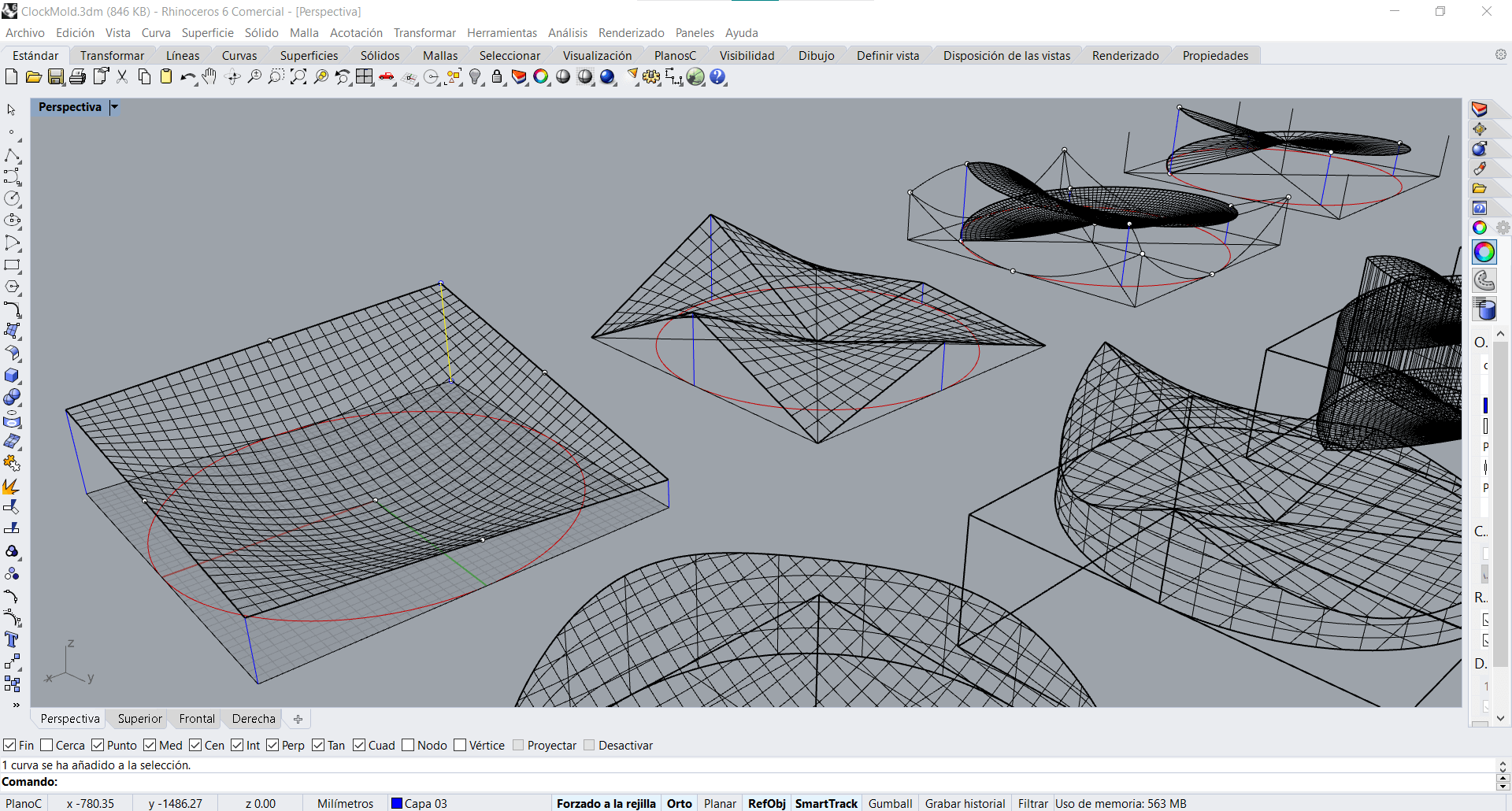
Design⚓︎
This design tries to represent a clock face, where the heights (blue lines) on the circumference are defined by the time references that a wall clock usually marks: 12h on the top, 3 on the right, 6 on the bottom and 9h on the left, converted to cm of height. Using this pattern I have decided to generate several surfaces with different geometrical concepts each. The first one is based on a hemisphere, the second on warped surfaces, the third and the fourth on a spiral with different profiles of revolution. In the pictures below you can see some details of the process and the final shapes.
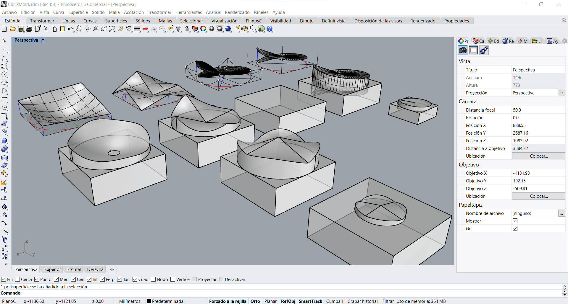
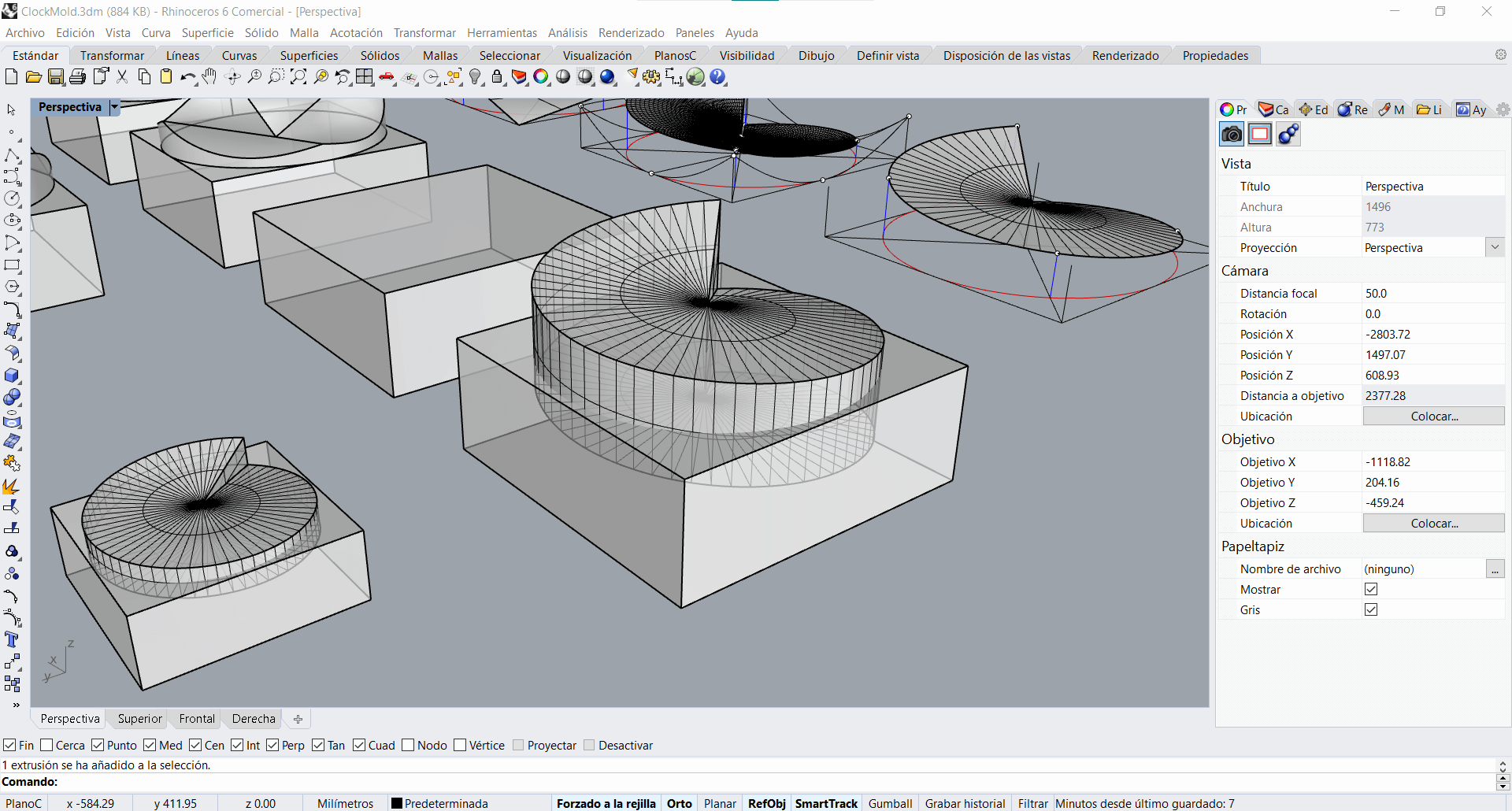
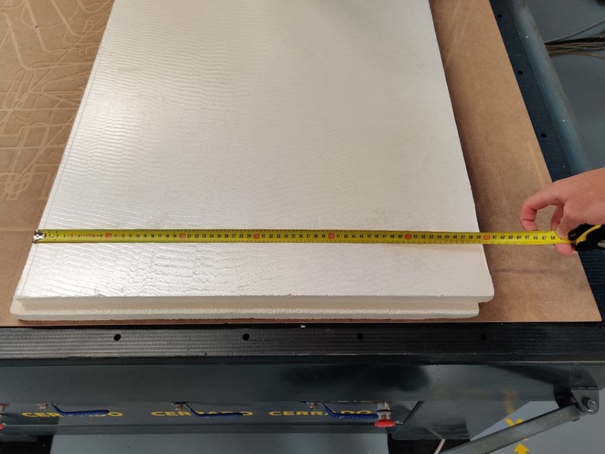
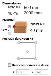
In the end I have decided to keep the second and the fourth surface, although I do not rule out the other designs for other iterations. For the material we will use a 60 x 200 x 4 cm (width, lenght, thickness) extruded polystyrene sheet. The problem is that the models have a height of 12 cm at their highest point so it is necessary to scale them in order to make the mould in one piece. Finally I have reduced the initial dimensions (40 x 40 x 12 cm) to a height of 3 cm -scaling also height and width to 20 cm in order not to disproportion the figure (proportion of X = 0.25, proportion of X and Y = 0.5)- to have also some margin in the material and not to mill the martyr if the Z offset gives a very tight measurement.
Note
If we had wanted to keep the dimensions of our original design but the thickness of the material is not enough, always make the mould in several independent pieces and then join them together. In this case, 4 sections would have been necessary to convert the 12 cm height of the piece into the 4 cm thickness of the material, maintaining the safety margin (3 cm sections) so as not to mill the bed martyr.
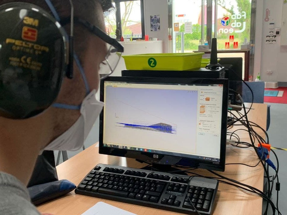
Aspire⚓︎
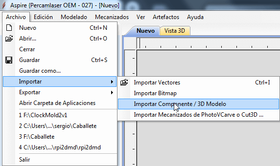
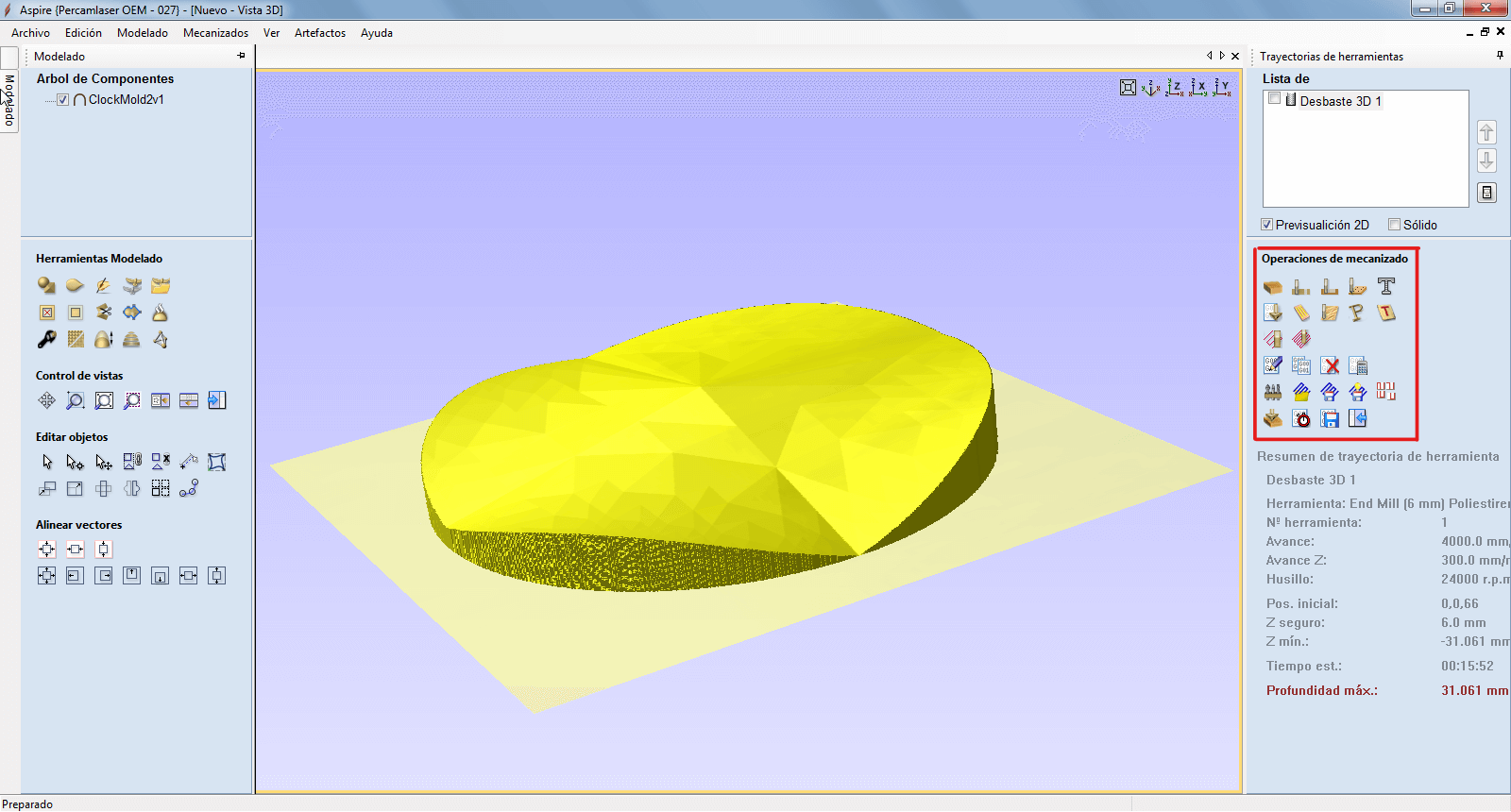
To work with the CNC we will use the Aspire VCarve software, as in Computer Controlled Machining week. The workflow with this machine and the software is documented in this assignment so the parts of the process that are the same will not be explained in further detail. To generate a new job, we open the software, create a new file and introduce the parameters of the material we are going to work with. It is important to establish the point of origin of coordinates in Z as well as in X and Y. Unlike the usual process for 2D cutting, we must import the file with the option Import > Import Component/3D Model. The model must have been exported as an .stl file.

Once we import the model, these are the steps to follow to prepare the milling of the part. Browse the tabs below to read a description of each process and the correlative picture.
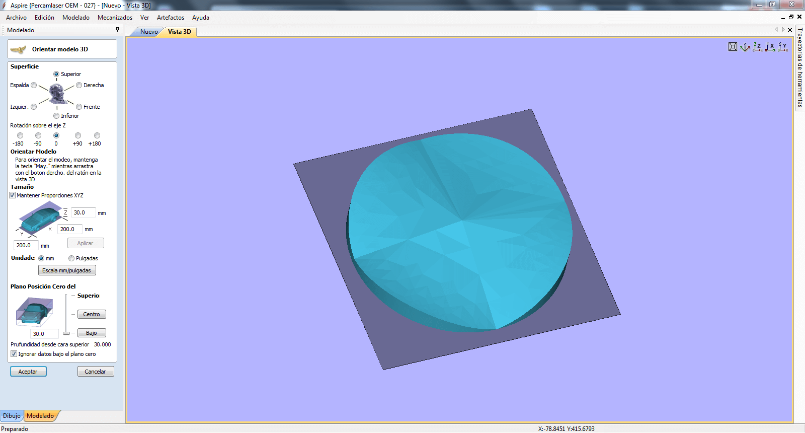
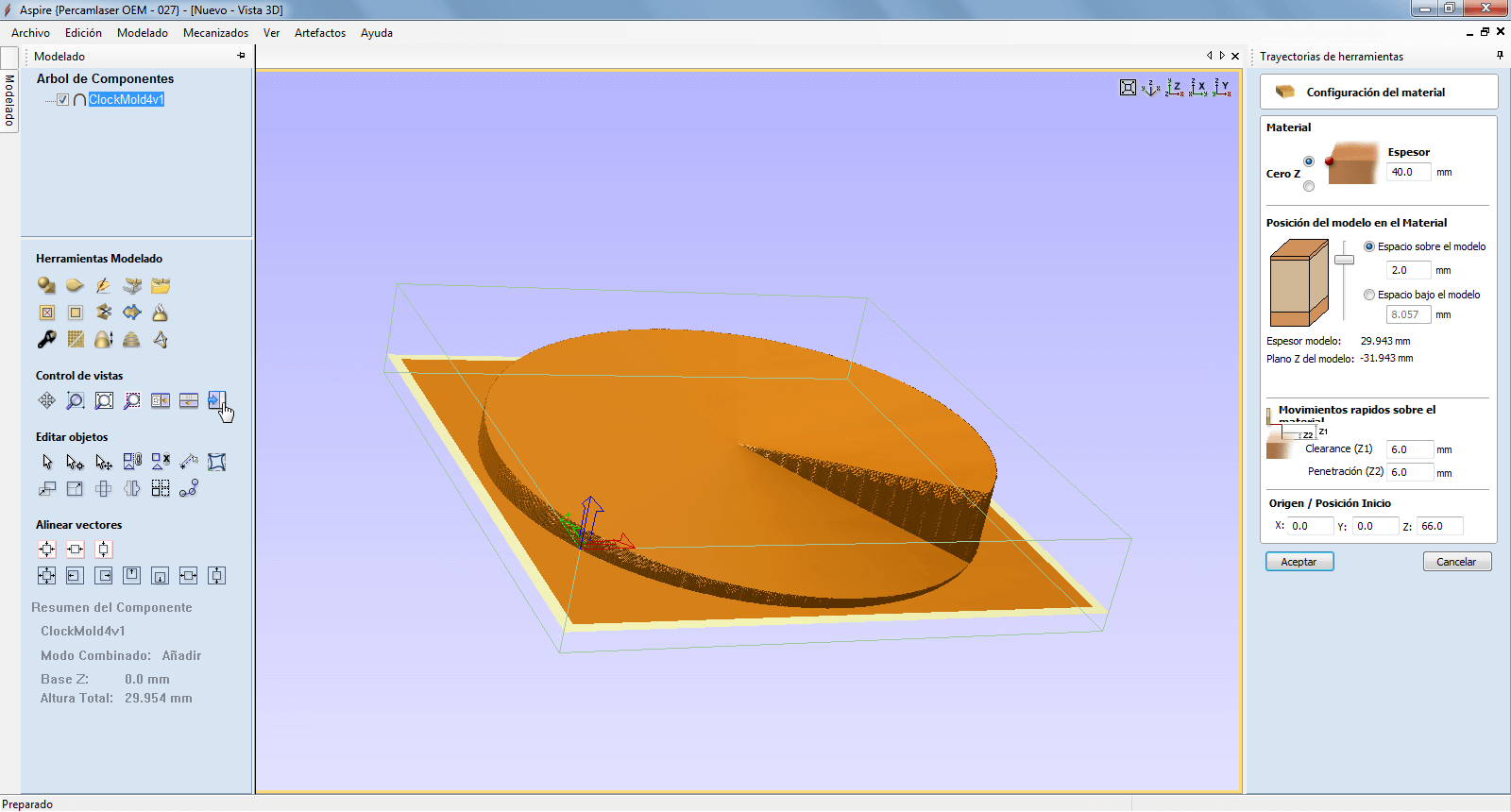
This is the first interface we come across once we have imported the model. It allows us to position the part based on the parameters of the material in the way we consider most suitable for milling. From this screen is where we can adjust the Z from which we want to place the piece, being able to fillet the model to make a mould in several parts without having to have previously divided it in the design. Very useful.
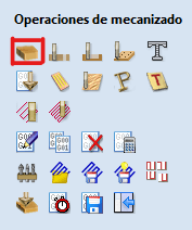
Below we can see the section of the delected model. All the parameters of the model are shown at the bottom right. It is useful to review them because they may reveal errors in the design or previous steps. From here we can select the desired machining tool, starting with the material settings and then the roughing settings or the process to be used.
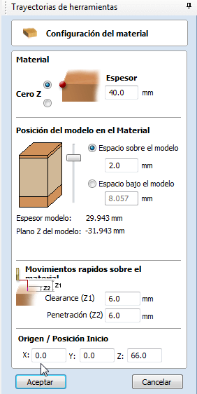
With this tool we define the real thickness of the material, which for the moment we will leave as the original, but later we must replace it with the one calculated using the Z probe with the vacuum bed on. We can also define if we want to eliminate a first superficial layer of the material so that the upper part of the piece is perfectly milled and no imperfection comes out due to the irregularities of the material on the upper face.
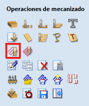
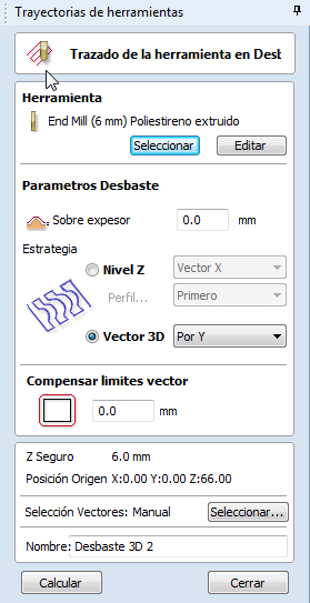
Here we must select the milling bit that we are going to use during the process. We also have to define the way in which the machine is going to generate the paths for milling the material. If we want to do it as a 3D vector in the direction of the X or Y axis, or as a circular path using the heights of the Z axis. It would be interesting to test what effect each of them has on the finish or the milling time, but I don’t know, so I have used the default one.
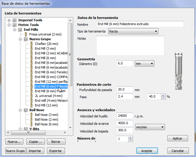
Finally, this is the menu that appears when we select the milling cutter. The default parameters of this tool are tested and adjusted by my colleagues, so it is not recommended to touch them. It is important to remember that we will have to select it again when the simulation is finished to export the gcode.
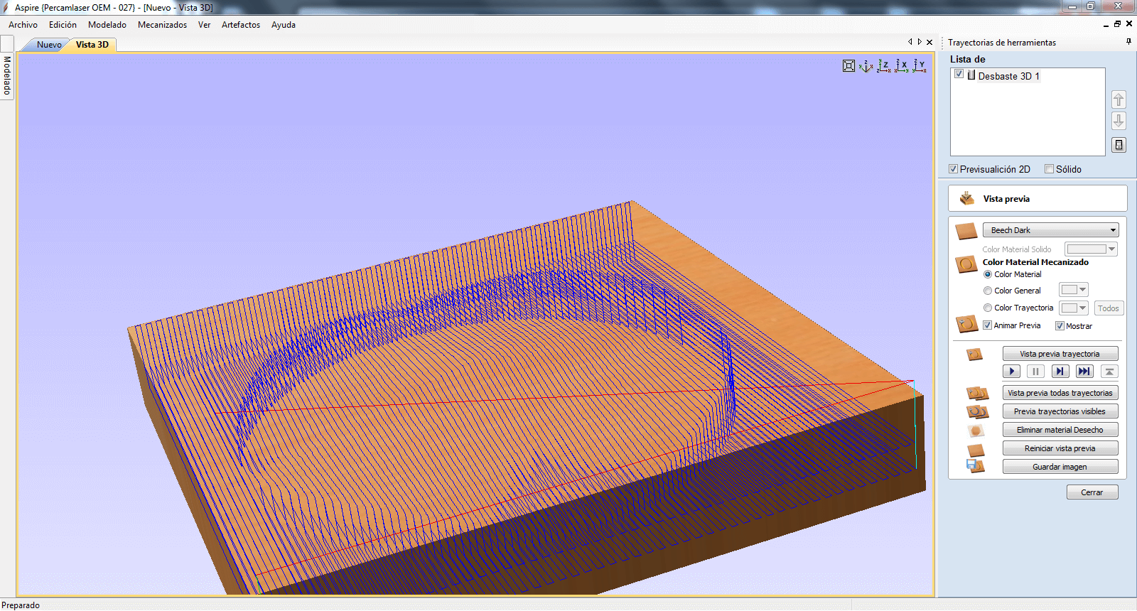
Once the tool and roughing parameters have been defined, we can generate a simulation through the software to visualise the result, all the traces of the milling bit and the operation time. In a late choice I have decided to change the model to the spiral one so I repeated all the process again
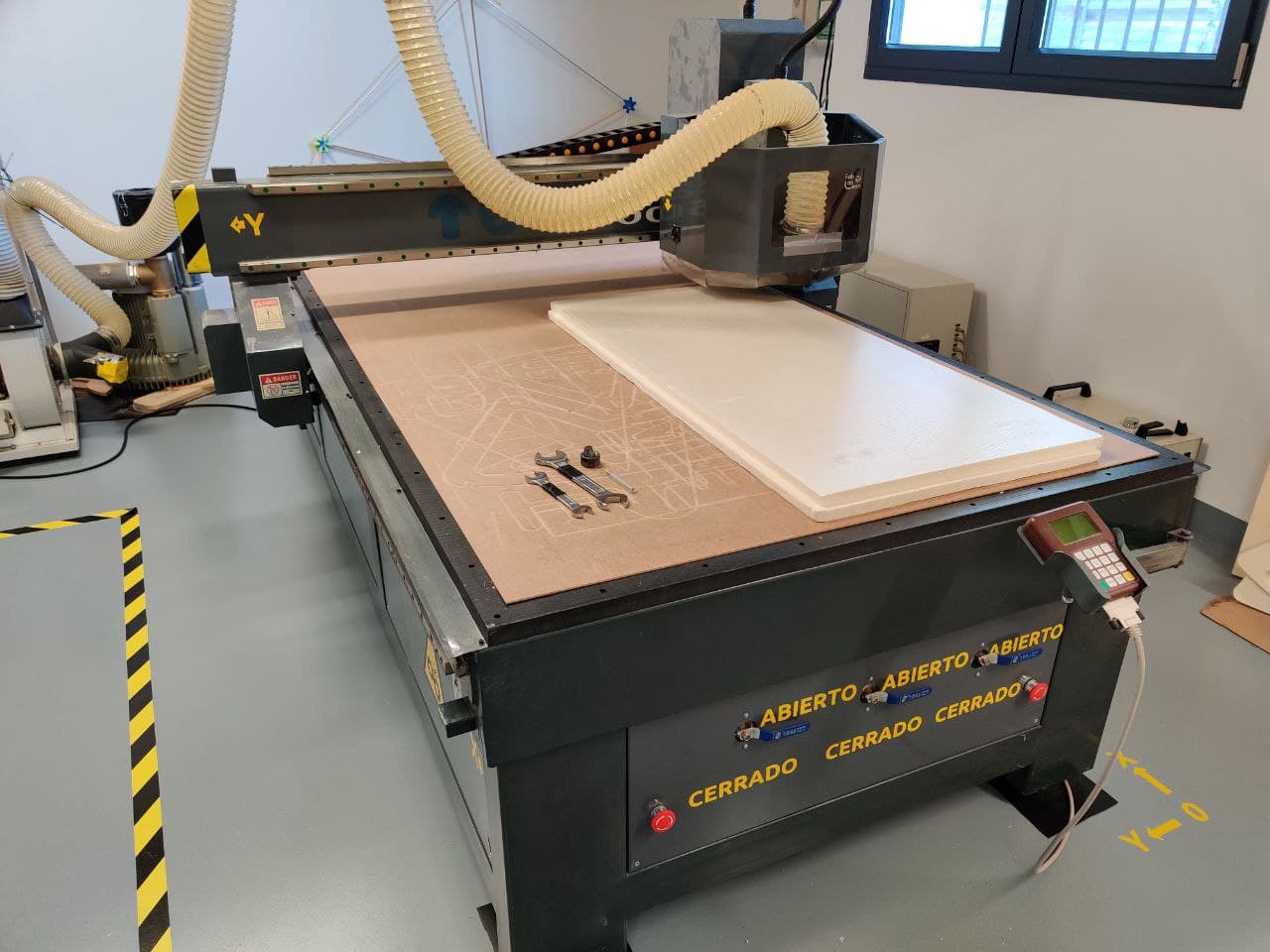
Milling⚓︎
The toy for this week. Again, all it’s details and safety protocols are documented in Computer Controlled Machining week.
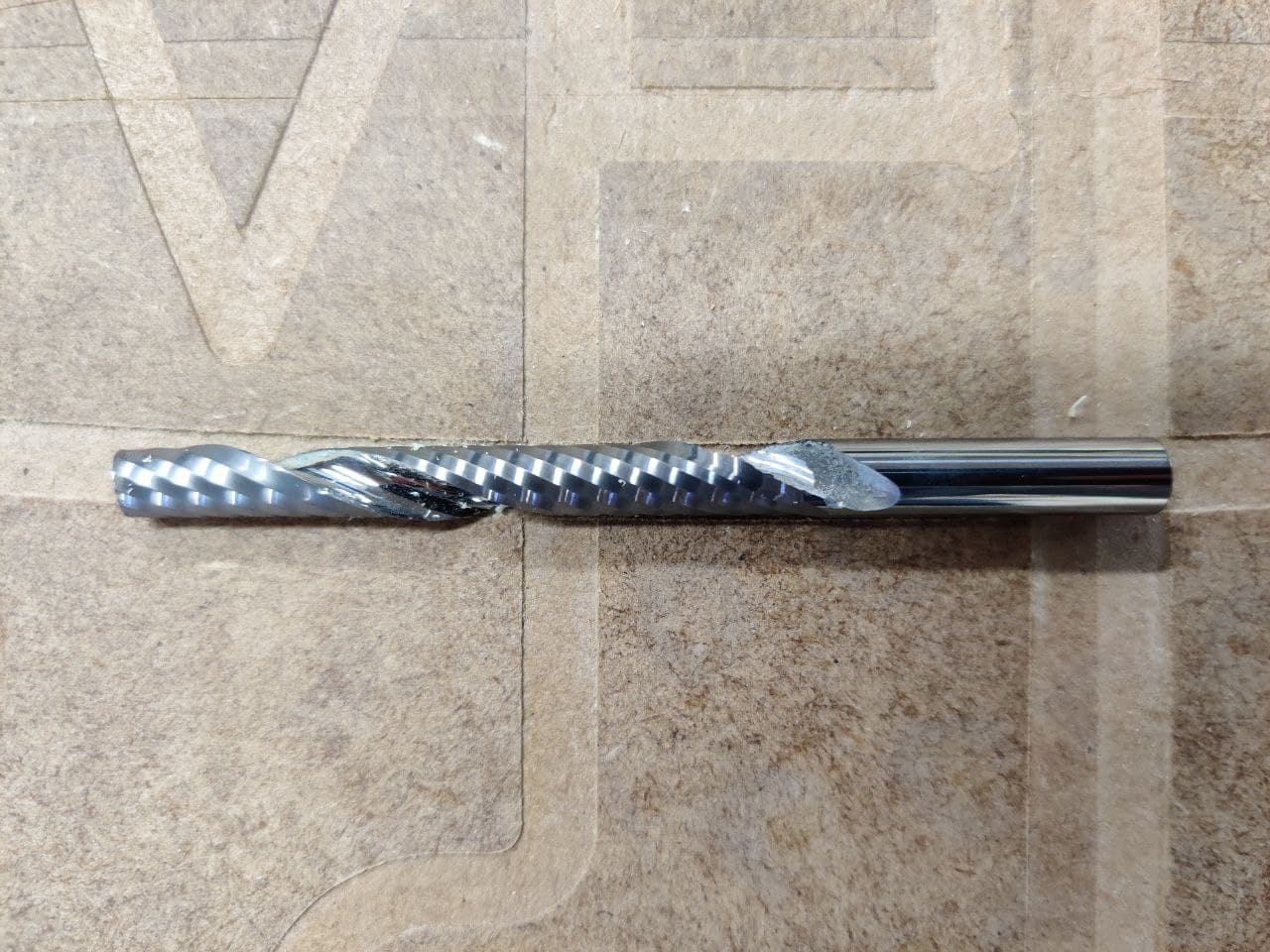
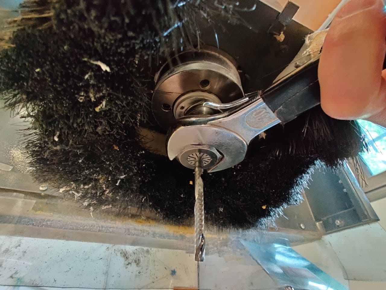
Milling bit: 6mm bilabial bit for extruded polystyrene
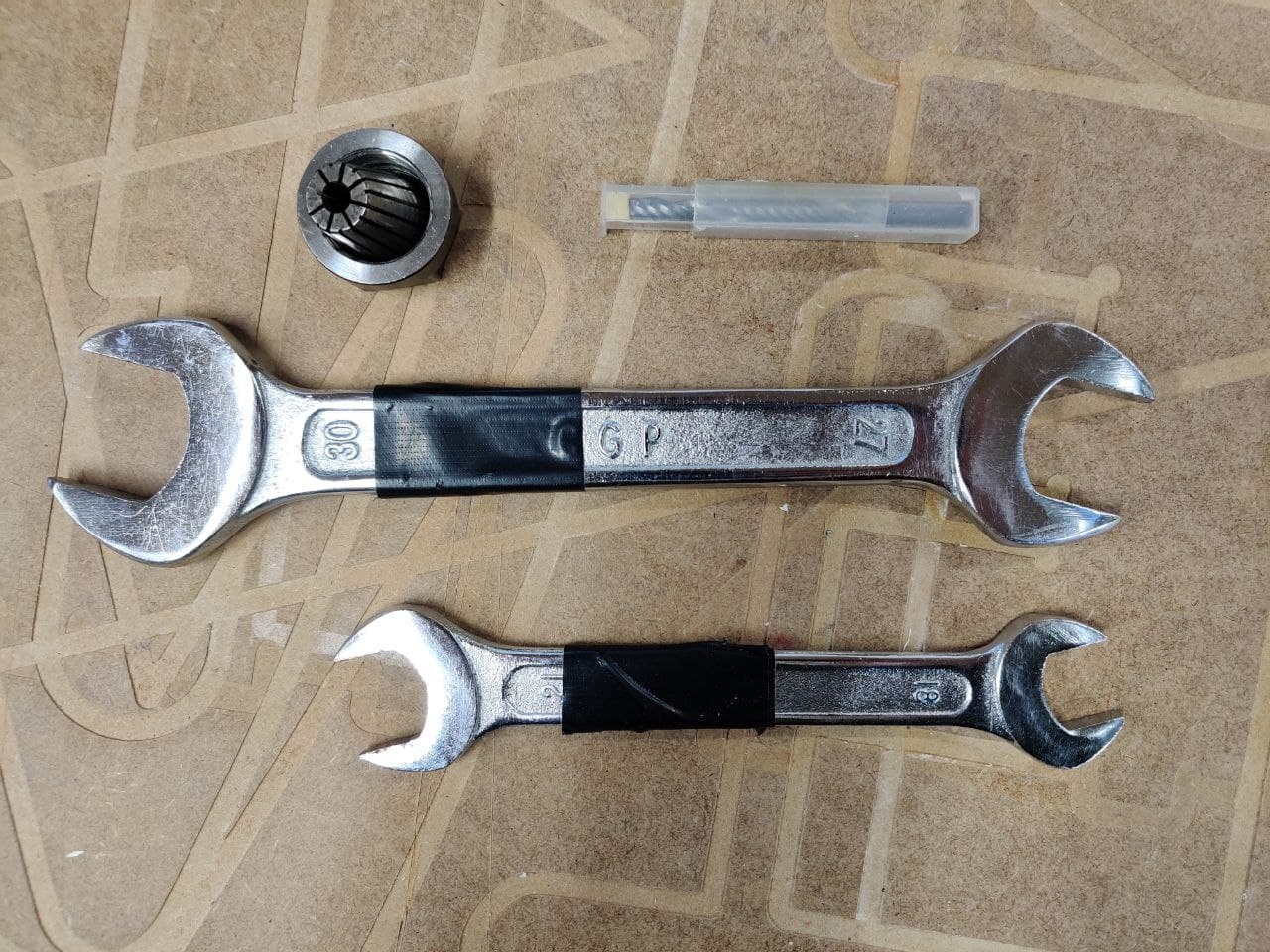
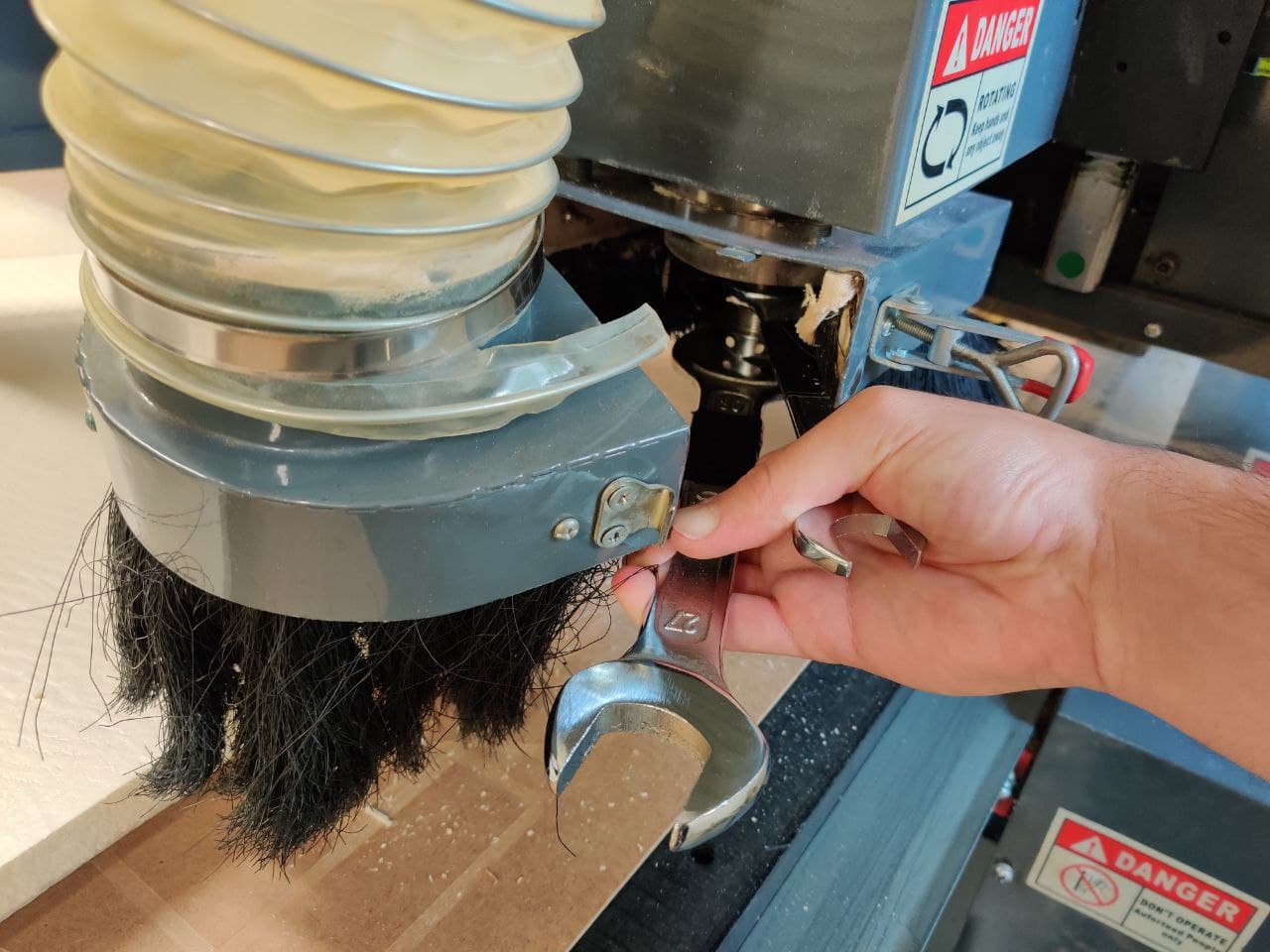
Positioning and tightening the milling bit
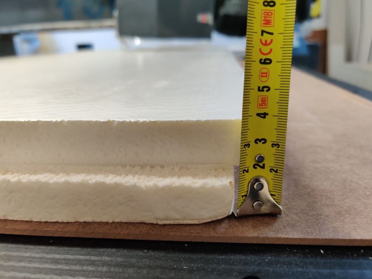
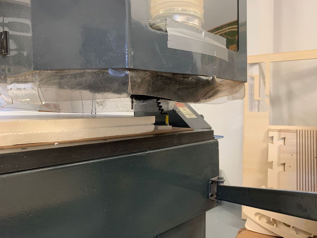
Measuring the thickness of the material with the vacuum bed turned on:
- Z on martyr: 55.887 mm
- Z on material: 17.028 mm
- Final thickness: 38.859 mm
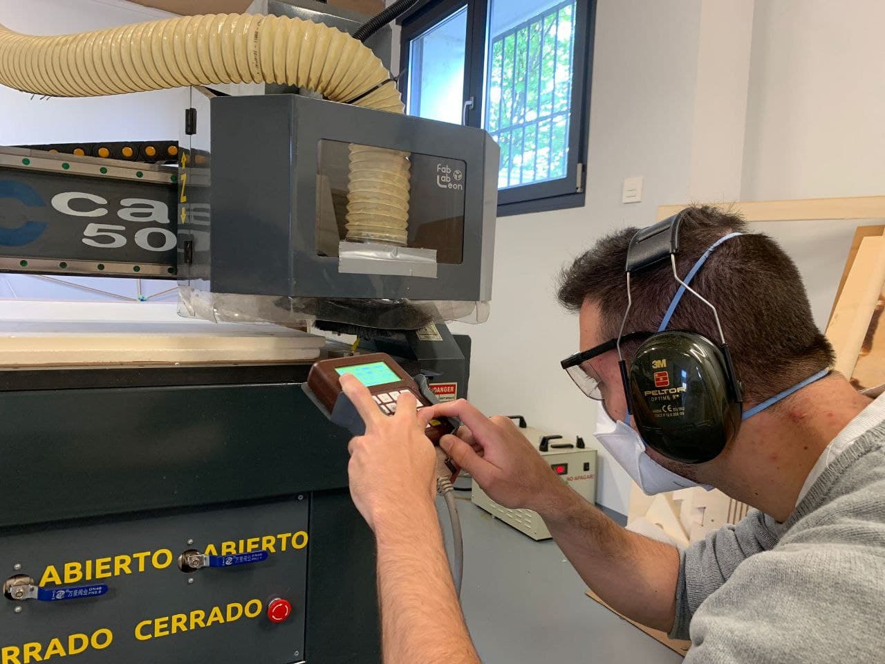
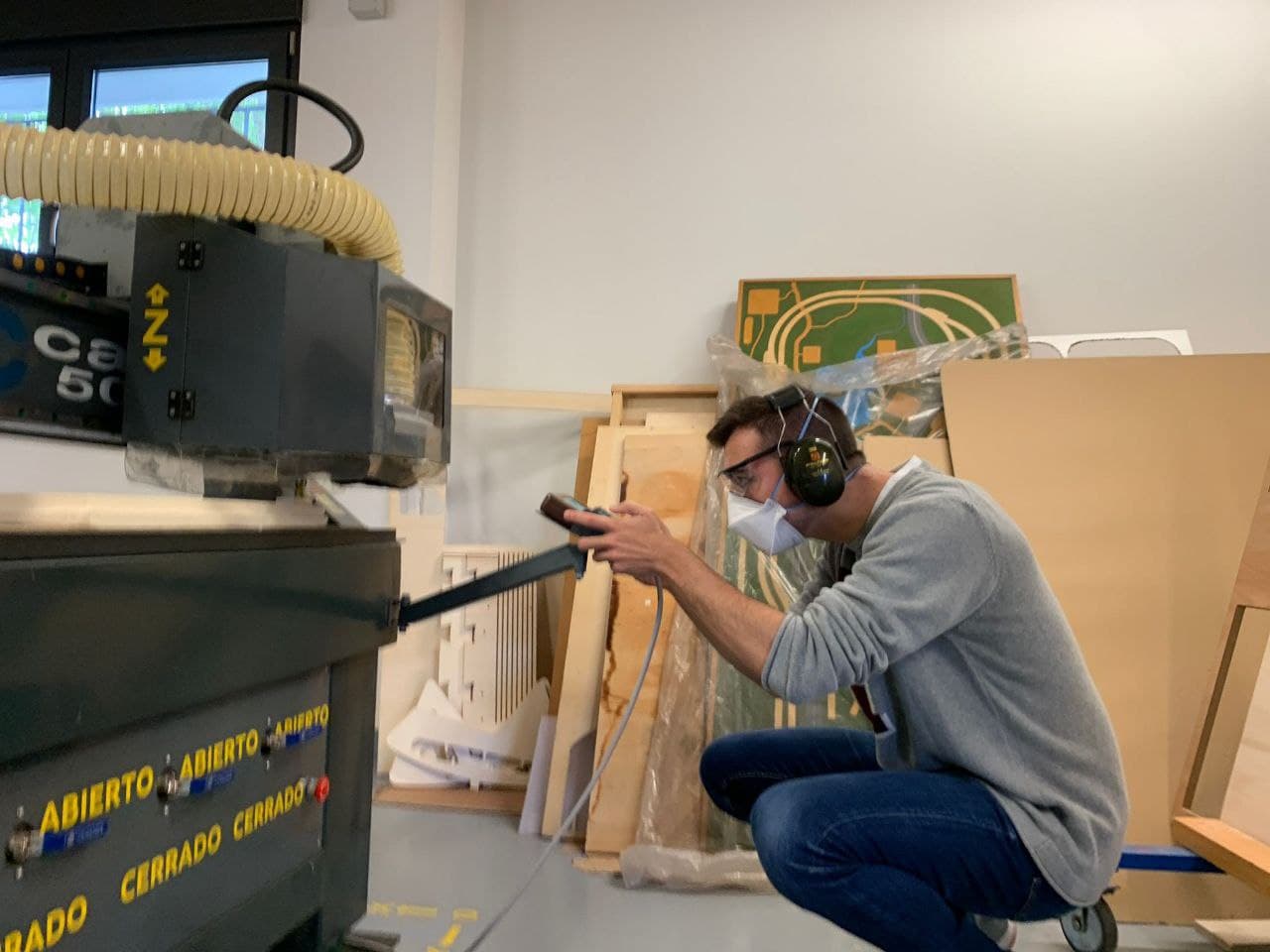
Once the correct thickness values have been entered and the milling simulation has been generated, we can export the gcode to the CNC flash drive. Then we plug it into the usb port of the mixer tap and press Run. We search for the file with the arrows, it’s usually at the bottom, which we can skip directly pressing up arrow at the top. Select the file again with Run and let the CNC start milling. We always have to check if the mill starts spinning so it’s recommended to keep a finger on cancel in case it doesn’t.
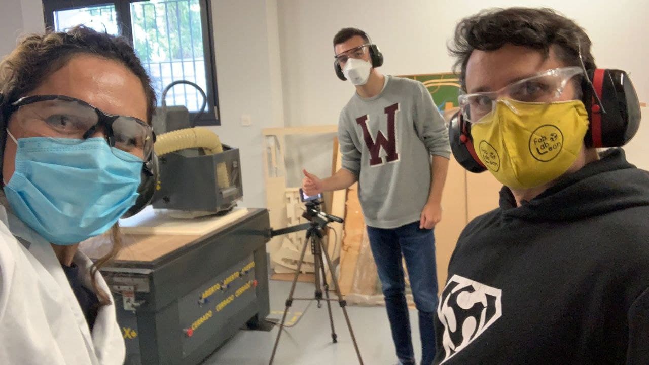
This is a lovely photo of me being accompanied by my instructors, they’ve been taking care of me. Nuria helped me with the composites process as she is a master of materials, and Pablo always give me a hand with the CNC because he has mastered this machine.
Timelapse
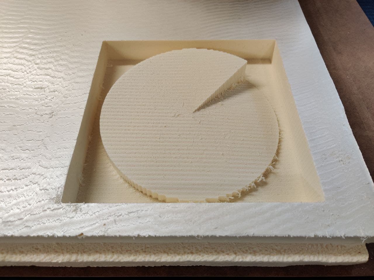
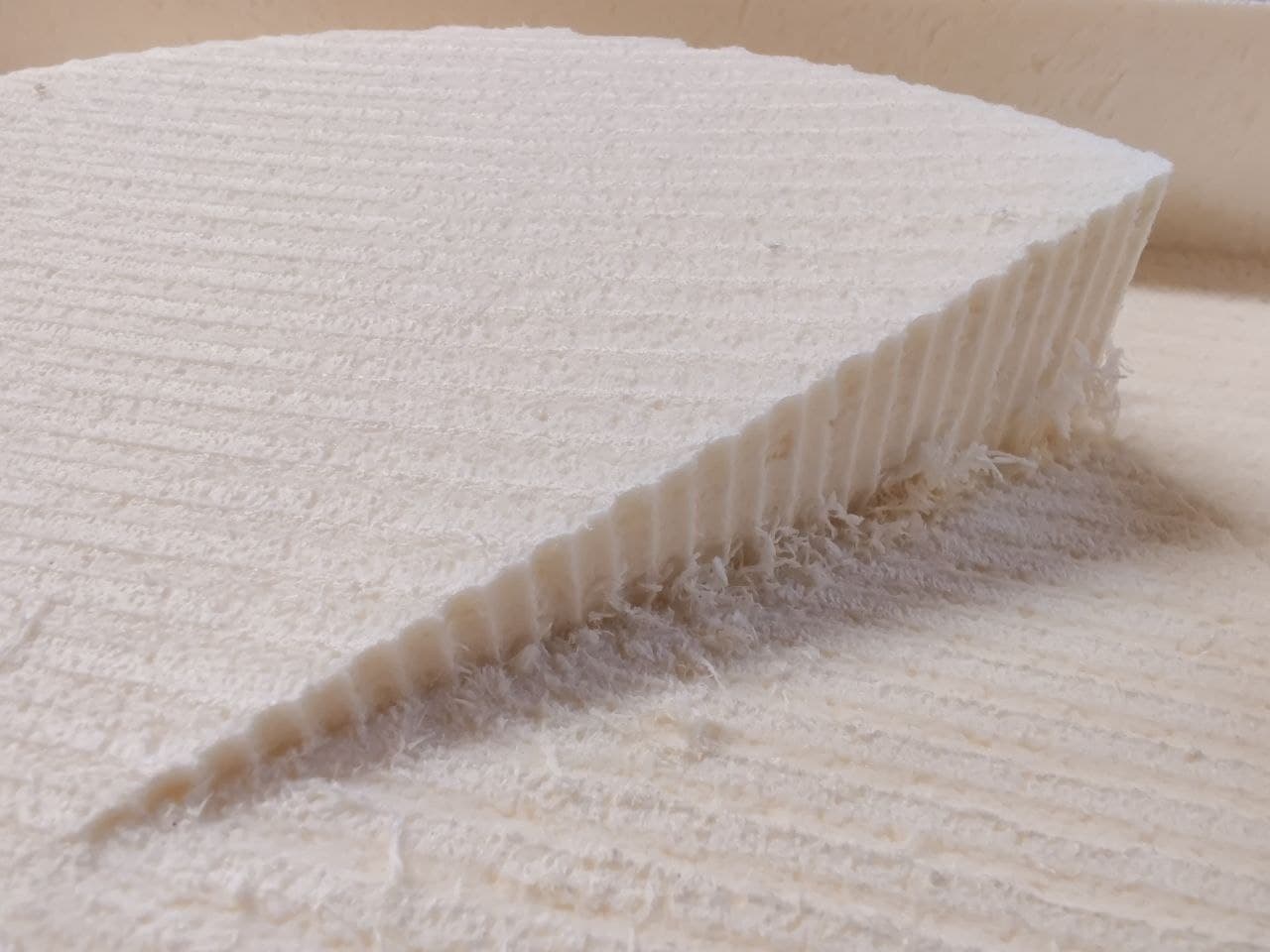
The result is shown in the phots below. I took around 15 minutes of milling, which is pretty quick, but this was due to just doing the roughing and not the finish. As I explained before, it wouldn’t make any noticeable difference in the texture finish of the composite.
Composites⚓︎
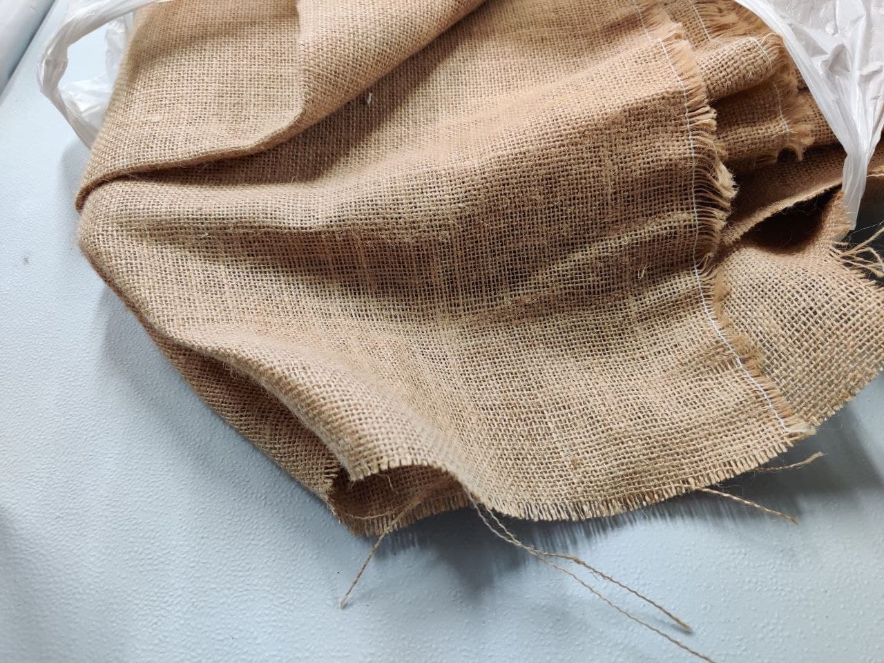
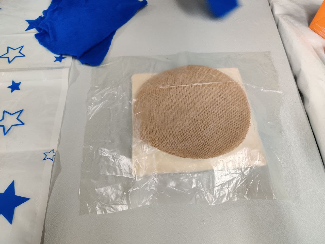
In this case I am going to use burlap as it is a strong fiber that can provide good stiffness when mixed with the resin.
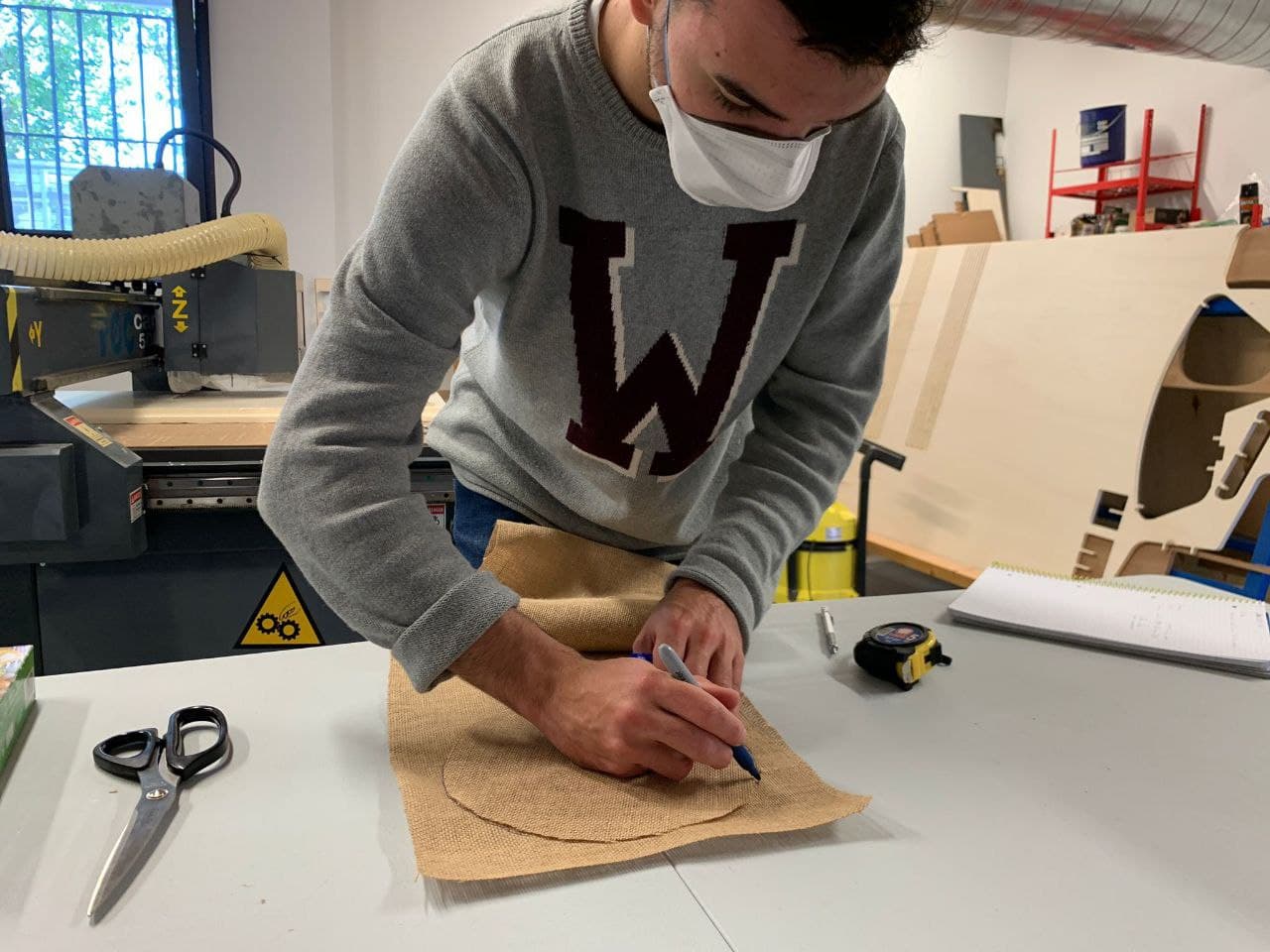
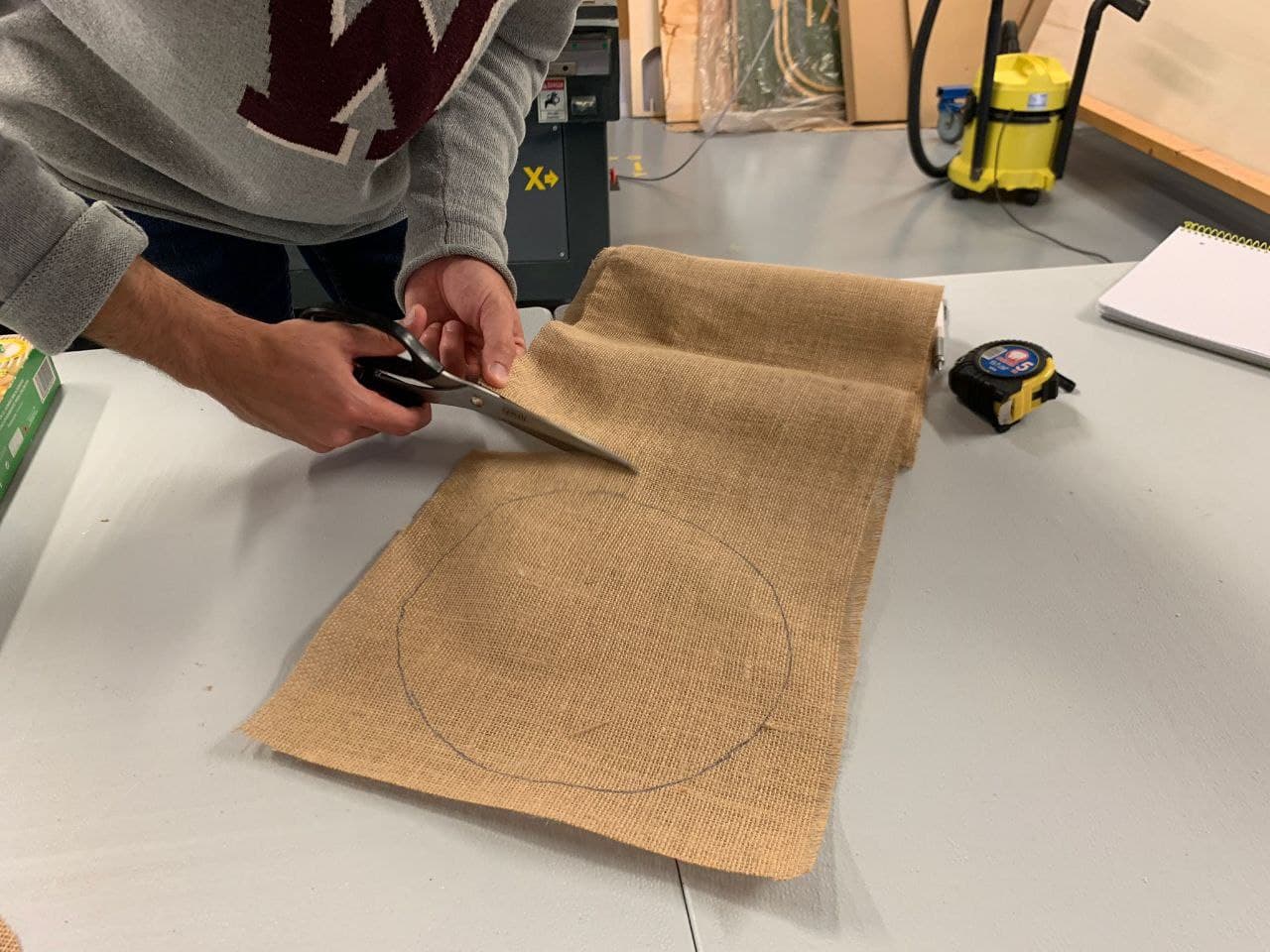
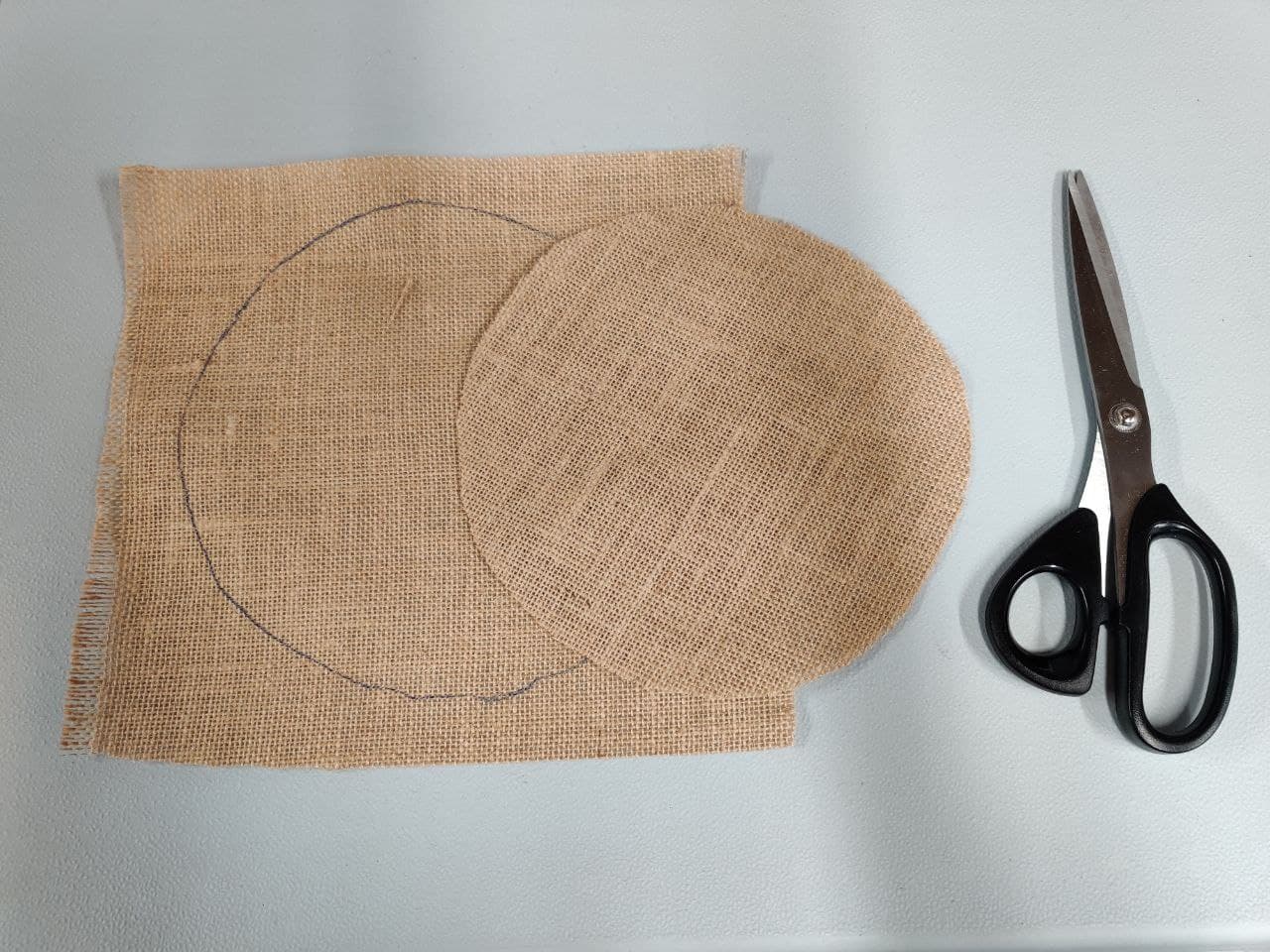
Fiber sizing⚓︎
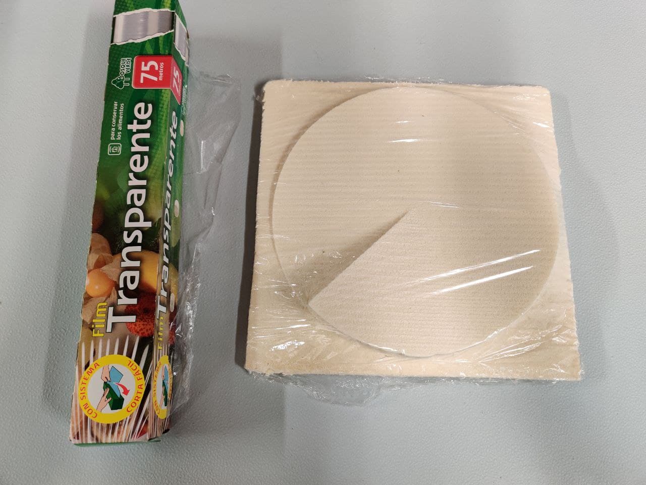
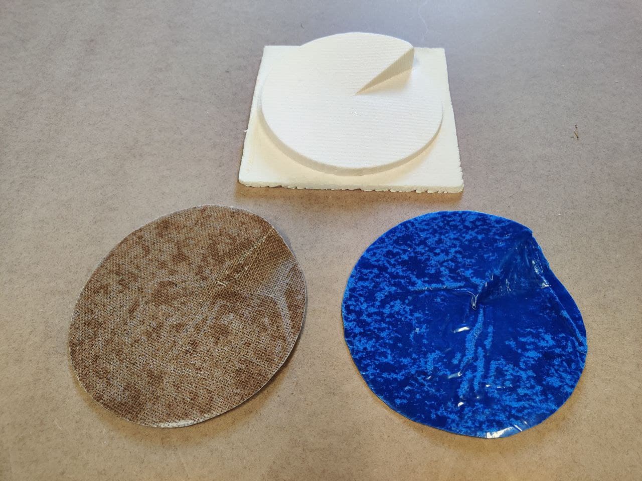
First we have to cut the material to size. Here we can use the mold as reference. Then we have to cut the fiber to the size of the mold as close to the desired final form as possible. For this test I will use two layers of burlap.
Timelapse of the whole process:
Casting the resin⚓︎
This will be our setup to make the composites. We are going to use Epoxy resin EC 131 LV with UV protection. You can find here the technical datasheet and safety precautions.
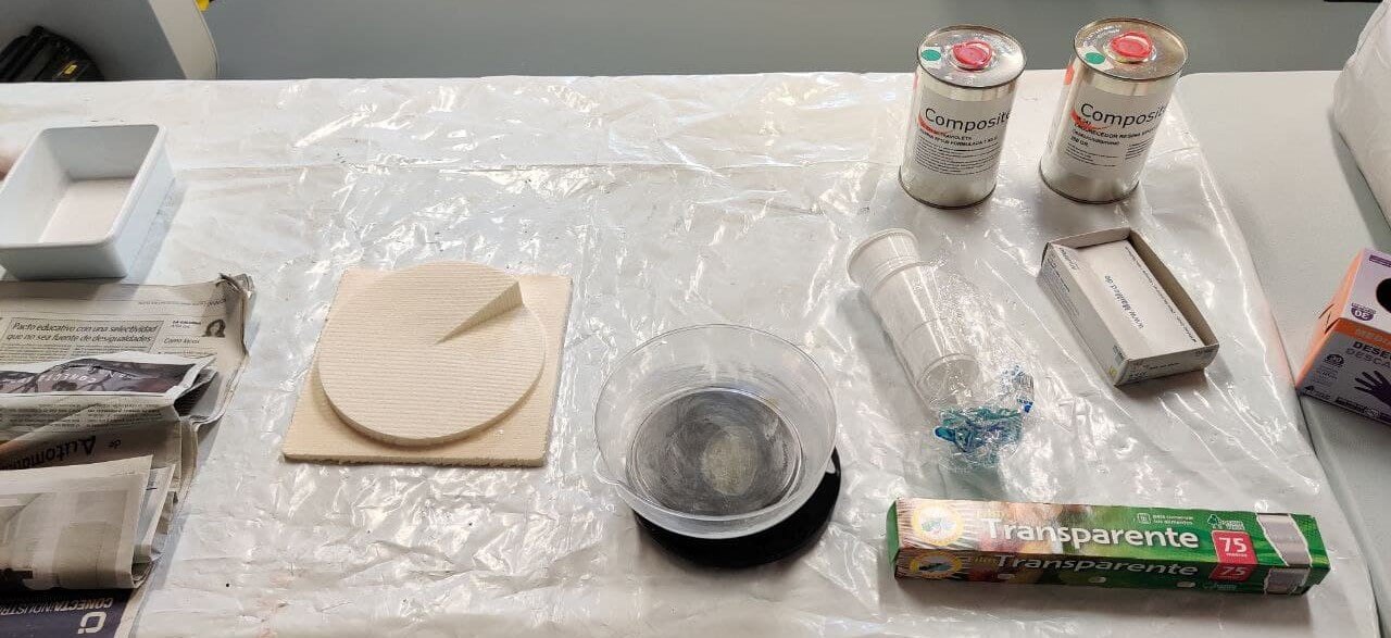
The mixing ratio by weight is 100 parts of EC 131 LV resin to 25 parts of W342 hardener. The most complicated thing is to establish the total amount of resin needed, as each fabric absorbs the resin differently and I don’t know how much material will be necessary to fill it properly.
Once we’ve got the mix, we have to spread it over the fiber, making sure the burlap absorbs as much resin as it can. We’ll do it with only one layer first, and when this one is soaked, we can put the second layer over it and repeat the spread process.
Wrapping the mold⚓︎
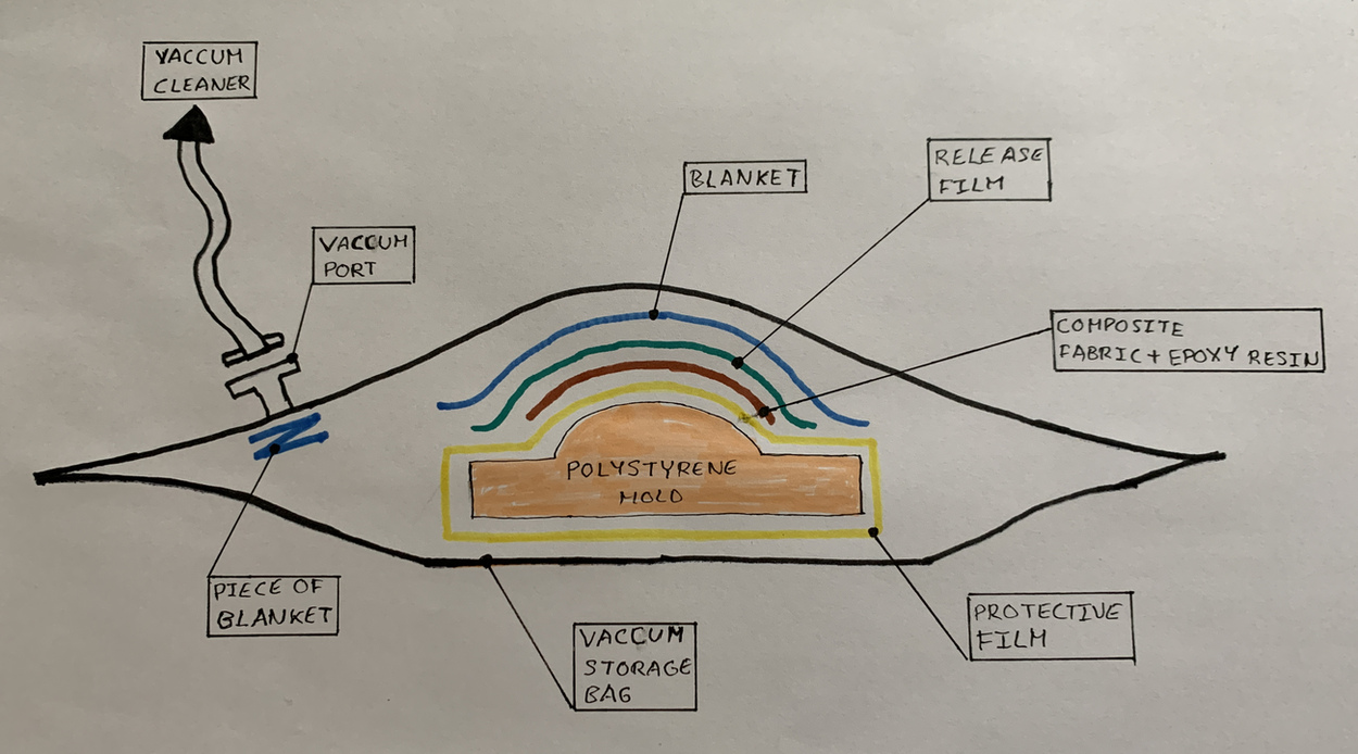
This proccess is a bit tricky, as the resin fiber is already impregnated in resin. We should pack it and vacuum it carefully to avoid contact with the resin and ensure that it doesn’t overflow. My intructor Adrian has a great drawing in his documentation about how all the layer pack one over another. I will explain the process by sequence, and it’s also documented in the photos below.
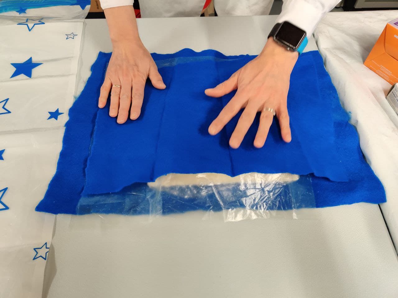
- We cover the mold with transparent film to be able to reuse it in future occasions. It is important not to leave gaps between the mold and the film, and to ensure that it is as stretched as possible, without wrinkles.
- Then we place the composite on the mold wrapped in film. We must ensure that it adapts as best as possible to the mold, since, although the vacuum will exert pressure on the composite against the mold, this will be the final shape it acquires.
- We place the perforated plastic on the composite, which will be in charge of letting the excess resin “sweat”. On top of this, we place the blanket, which should absorb said resin.
-
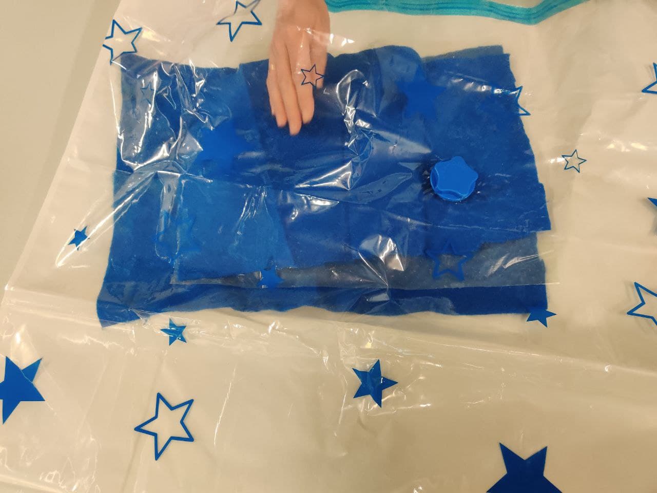
We introduce the package into the vacuum bag, and apply suction with the vacuum cleaner through the valve.
Tip
Nuria has given me a series of advice from having done this process many other times. Among them are:
-
If possible, place a blanket below the mold and an extra blanket above it, with a separating plastic layer. As there is more material, the pressure will be greater and more uniform.
-
It is advisable to leave the suction valve to one side of the package and not on top, so that it makes a uniform pressure and does not directly suck an area.
-
Folds in the vacuum bag should be avoided, because they are areas where air is stored and during curing this causes the vacuum to lose pressure.
-
These photos were made during a first example trial in which Nuria showed me the whole process before making the composite, to be able to replicate it later. Below it’s a timelapse of the “real” process. We have had an issue with the vacuum bag, as the first one was losing vacuum through some hole. After checking if we missed any gap in the zipp, we have had to change it for another one.
Curing and result⚓︎
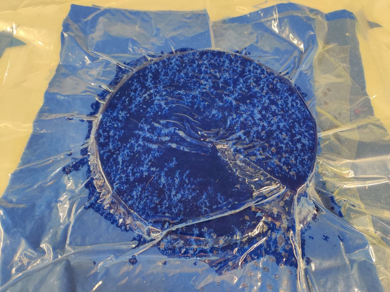
We have to let the composite cure for about 24 hours with the vacuum sealed preassure. We can also use heating process for curing but it’s not mandatory. The resin has sweated so much through the film with holes that the blanket itself has formed as another composite.
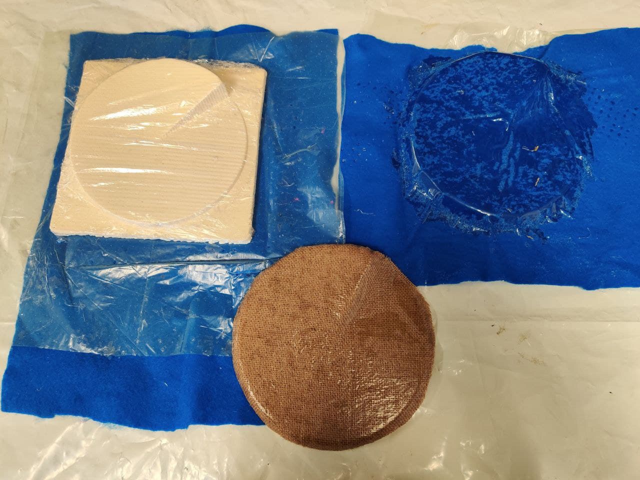
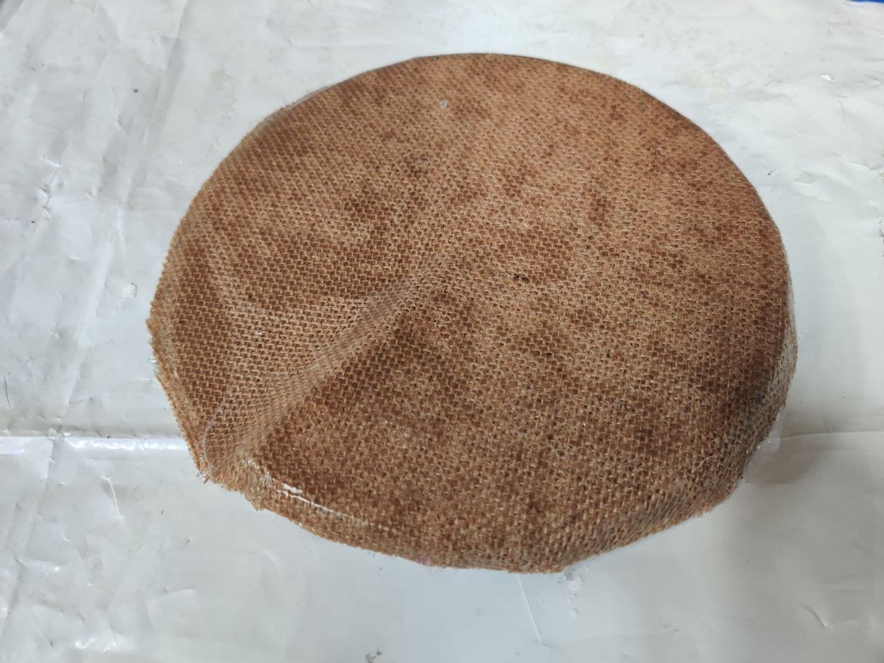
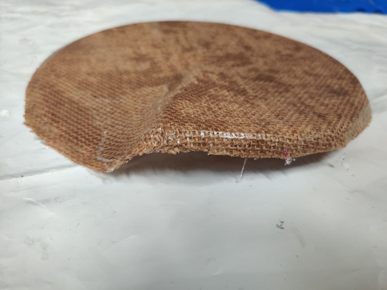
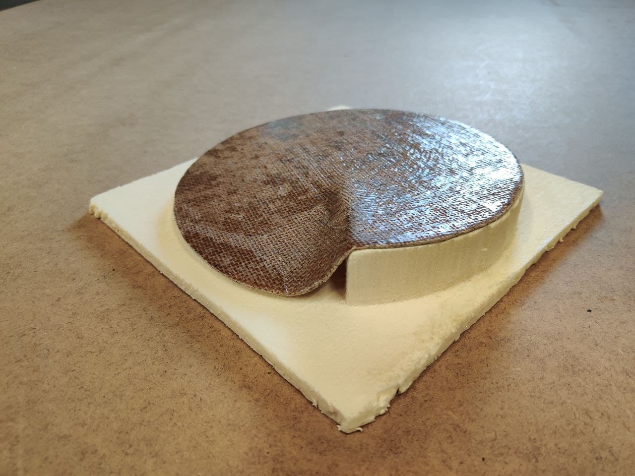
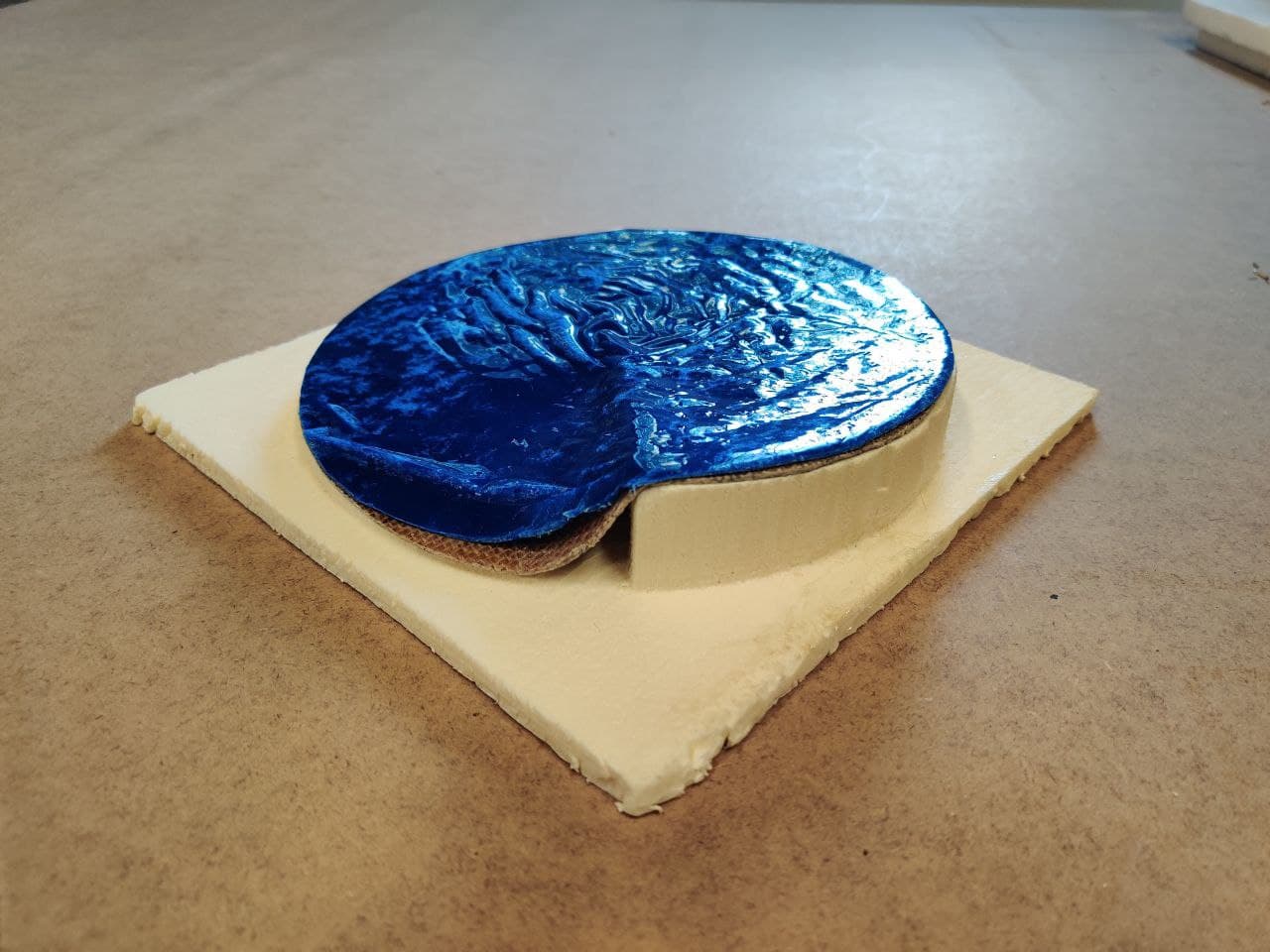
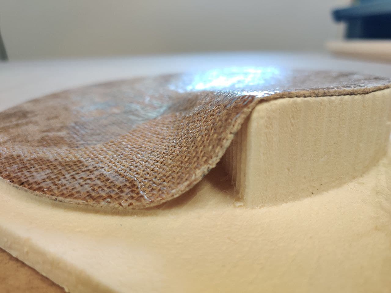
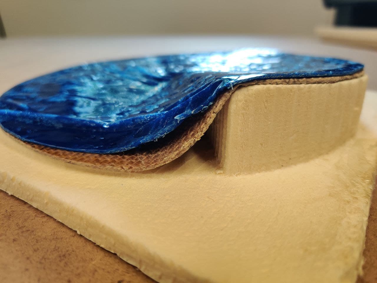
The result hasn’t been as desired, because the surface finish isn’t smooth. It looks like there wasn’t enough resin, or that it has sweated too much. Also the shape hasn’t taken the exact form of the spiral, probably because it’s impossible that the area of a circunference extends to have an extra vertical side. There isn’t any practical solution for this, as cutting just in the edge would have made the spiral but not the vertical wall.
Overall working with composites has been fun, but most important, it has shown me that by mixing materials you can extract the most of both best properties. I’ve seen this before, when studying reinforced concrete at material subject in architecture, but doing it by yourself and with a material like fiber is pretty cool.
Files⚓︎
- Rhino design file with all the clock mold models(
.3dm): file - Scaled spiral clock mold model that was milled(
.stl): file