7. Electronics design⚓︎
This sixth week is about electronic design. I have very little knowledge about electricity and electronic design, so let’s see how far can I get and how much can I learn! Here are the Assesment Criteria related to the seventh assignment, Electronics Design:
-
- Use the test equipment in your lab to observe the operation of a microcontroller circuit board (in minimum, check operating voltage on the board with multimeter or voltmeter and use oscilloscope to check noise of operating voltage and interpret a data signal).
- Document your work (in a group or individually).
-
Individual assignment
- Redraw one of the echo hello-world boards or something equivalent, add (at least) a button and LED (with current-limiting resistor) or equivalent input and output, check the design rules, make it, test it.
-
Learning outcomes
- Select and use software for circuit board design.
- Demonstrate workflows used in circuit board design.
-
Have you?
- Linked to the group assignment page.
- Documented what you have learned in electronics design.
- Explained problems and how you fixed them, if you make a board and it doesn’t work; fix the board (with jumper wires etc) until it does work.
- Included original design files (Eagle, KiCad, - whatever).
- Included a ‘hero shot’ of your board.
- Loaded a program and tested if your board works.
Hello.ftdi.45⚓︎
We meet every Thursday morning on Teams to talk about the week assignment and start with the work, so this one Nuria gave us a master class of electronics for beginners. As you can see in the screenshot of the meeting, we’re discussing the last theory about quantum physics. 

The goal for this assignment is to make our own board, an our instructor have recommended us to start with the basics, so I will try to replicate Neil’s hello.ftdi.45 board and add to it a button and a led. The plan is to program it later and see if it works. A working push to blink will be a great achievement.


Design⚓︎
For the design of our board we need an EDA software. In this case we are going to use Eagle because of the familiarity with the Autodesk work environment, although I don’t rule out trying KiCad in the future.
Libraries (.lbr)⚓︎
First of all we need to have included the libraries of the components we are going to use and the design rules for our board. In this case we are going to use some specifically designed for FabAcademy that will make our work easier later on. Both can be found in FabAcademy’s own Eagle tutorial, which has been pretty usefull for learning this tool, or in the GitLab libraries archive, that are the ones linked below.
To install them we only have to download both files, go to the program folder created after the installation of the program in Documents, and copy the respective files into their corresponding folder: PC/Documents/Eagle/libraries/fab.lbr; PC/Documents/Eagle/designrules/fab.dru

If we have done the above process correctly, we should be able to see these files in the menu that appears on the left when we start Eagle, with the drop-down menus for each folder, as shown in the picture above. We also have the option to change the default folder where Eagle will look for these files, but this should not be necessary unless we have moved the program folder from its original location.
Schematic (.sch)⚓︎
To start designing the board we need to create a project. In order to do that, follow File > New > Project from the top bar. In this project we will include all the files of our board design, such as the schematic and the board. To generate a schematic file in our project: Right click on the project > New > Schematic. Our window with the schematic interface should have opened.
Now we can start adding the components of our hello.ftdi.45 board to the schematic. To add components we can either type add directly on the command line or use the shortcut bar button with the shape of a plug and a plus. This opens a window with all available Eagle libraries. We should look for the one mentioned as fab, which is the one we downloaded earlier. We use this library because it is adapted to the components in the FabAcademy inventory, as well as having some changes in the design of the component footprints to make it easier to solder them to the board.

One of the difficulties of the schematic is to find the specific components corresponding to our board, even in a reduced library like fab. That’s why I’m including a list of the hello.ftdi.45 board components, in case I can save someone from suffering. In case of doubt, I have selected those indicated as fab, following the recommendations of my instructors:
| Component | Librarie name | Quantity |
|---|---|---|
| Microcontroller | UC_ATTINY45SI | 1 |
| FTDI connector | CONN_06_FTDI-SMD-HEADER | 1 |
| ISP connector | CONN_03X2_AVRISPSMD | 1 |
| Resistance | R1206FAB | 2 |
| Capacitor | CAP_UNPOLARIZEDFAB | 1 |
I have started working on the schematic by routing all the connections but my instructors have suggested me to label the connections as it gets less messy and it’s less likely to miss a connection.


The assignment requirements say that we have to create a new board or at least add components to an existing one, so I added the previously thought led and button with it’s pullup resistor. These are the specific fab library components:
| Component | Librarie name | Quantity |
|---|---|---|
| Button | SW_SWITCH_TACTILE_6MM6MM_SWITCH | 1 |
| Resistance | R1206FAB | 2 |
| Led | LEDFAB1206 | 1 |
Board (.brd)⚓︎
Once the schematic is finished, we can generate the board file from it. To do that we have a red and gray button with the letters BRD on the top toolbar. All the components will appear with their footprints agglutinated at the bottom right. We must place them inside the black rectangle design box and begin to configure what will be their real layout on the milled board.


As you can see in the last image above, I haven’t managed to route all the traces directly so I’ve had to use two 0 Ohm resistances as jumpers for the traces. This is far from ideal but since it’s my first time routing a board I’ll take it for this time.
Now that the board design is finished we have to check the design rules to make sure the board can be milled correctly and there isn’t any missing connection or faulty trace. Apart from some minor errors such as overlaping traces that are the same, the board passes the “test”! 


Finally we have to export the board as a .png image, since it is the format which we work with for milling with the Modela. We must make sure to hide all the layers in Eagle except for the traces, since otherwise the rest of the diagrams will appear in our design (as you can see from the different attempts documented below). Another important aspect is the export settings. The image must be exported in monochrome and with a resolution of 1000 dpi.


Gimp (.png)⚓︎
Editing the file in Gimp to center the board, add a signature and create the exterior milling path archive.


Final result⚓︎
This are the final png’s to use for milling.


Fabrication⚓︎
This process was detailed two weeks ago in the Electronics production assignment so I won’t get into much detail.
Milling⚓︎
I’ve made a pretesting in the online version of Mods CE to check if the path generated was looking fine, and it was, so back at the lab I milled the board using FabModules and the Modela. Same speed settings and workflow as two weeks ago.


Soldering⚓︎
As you may observe, this isn’t the same workstation as two weeks ago. That’s because I’ve come home this weekend to see my family, but since fabacademy doesn’t rest, I’ve brought my homework with me. My collegue Alberto has had the detail of inviting Lorena and me to his FabLab at the European University, to work here all day on the assignment.


Testing⚓︎
Electronics⚓︎
Testing continuity, I have suddenly found an error in the design board. As I have used the routed version of the schematic and not the labeled one, apparently I’ve missed a connection between all the VCCs traces. They’re splitted in two sections so power it’s not flowing as it should thorugh the board.
I’ve come back to Eagle to check the error and fix the design, but since the board was already soldered and it was just a matter of a connection Nuria suggested to make a bridge with a wire. I will save the updated design for future iterations but for this time Frankensteining the board has saved the work!


Programming⚓︎
From Arduino, in the preferences tab we will add the URL to load the Arduino IDE with other cards or microcontrollers like the ATtiny45 we are using. Spence Konde has a guided tutorial for this proccess. The boards manager URL is:
- Select
Files>Preferencesat the top right menus toolbar. - Find the field
Manager of additional card URLs. - Paste the following URL in the field (we will use a comma if there is any other URL in the list):
https://raw.githubusercontent.com/damellis/attiny/ide-1.6.x-boards-manager/package_damellis_attiny_index.json - Select
Tools>Board>Card managerand write ATtiny in the search field. - Click on ATtiny by David A. Mellis and select install.
- After the installation close the board manager window.
- Select
Tools>Boards>ATtiny25/45/85 - Select in
Processorthe ATtiny45 and then inClockselect the internal clock frequency 8MHz.


Blink⚓︎
Once we have set our enviroment for uploading the code, we can load a simple blink test from the Arduino examples library.


// the setup function runs once when you press reset or power the board
void setup() {
  // initialize digital pin LED_BUILTIN as an output.
  pinMode(3, OUTPUT);
}

// the loop function runs over and over again forever
void loop() {
  digitalWrite(3, HIGH);   // turn the LED on (HIGH is the voltage level)
  delay(1000);                       // wait for a second
  digitalWrite(3, LOW);    // turn the LED off by making the voltage LOW
  delay(1000);                       // wait for a second
}
Button⚓︎
// constants won't change. They're used here to set pin numbers:
const int buttonPin = 4;     // the number of the pushbutton pin
const int ledPin =  3;      // the number of the LED pin

// variables will change:
int buttonState = 0;         // variable for reading the pushbutton status

void setup() {
  // initialize the LED pin as an output:
  pinMode(ledPin, OUTPUT);
  // initialize the pushbutton pin as an input:
  pinMode(buttonPin, INPUT);
}

void loop() {
  // read the state of the pushbutton value:
  buttonState = digitalRead(buttonPin);

  // check if the pushbutton is pressed. If it is, the buttonState is HIGH:
  if (buttonState == HIGH) {
    // turn LED on:
    digitalWrite(ledPin, HIGH);
  } else {
    // turn LED off:
    digitalWrite(ledPin, LOW);
  }
}
Redesigned board⚓︎
Since I had some time left for the week I’ve decided to redo my board design. This will help me getting better at electronics design and also fix all the errors I have been accumulating in the first design. From the resitances as jumpers to the faulty VCC trace. After some rethinking I have finished with this design. It looks much cleaner, it doesn’t need jumpers and it should work without Frankesteining. 

The design file from Eagle such as the schematic (.sch) and the board (.brd) are uploaded to the repo and linked at the bottom of the page for anyone who may want to fabricate it. I didn’t have time to make the traces and exterior .png files for this one.
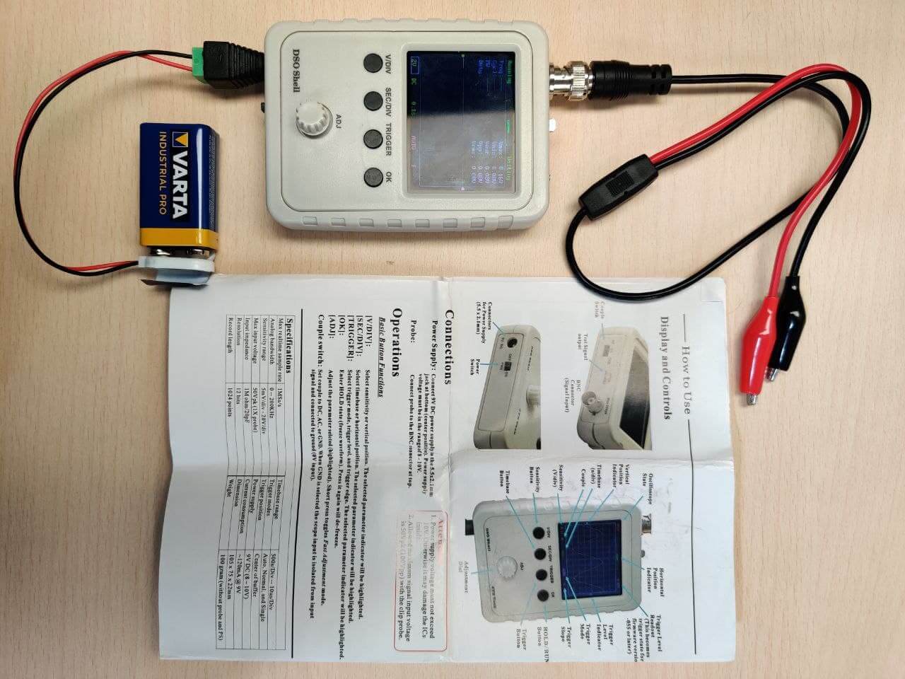
Group assignment⚓︎
For this group assignment we have to use the test equipment in the lab to observe the operation of a microcontroller circuit board. I will be using the multimeter and also cheking how the oscilloscope works for future needed aplications.

More by obligation than by assignment requirement I have had to use the multimeter to measure the voltage of the tracks of my board, to find where the error was in the design of the board.
Update
I have used also the multimere in a lot of assignments, but it was really usefull during Output Devices week to calculate the power draw of each output device. I’ve also used the oscilloscope during Input Devices week to understand how the ultrasonic sensor trigger and echo pulses where working.
Files⚓︎
- Traces of the hello.ftdi.45.ledbutton (
.png): file - Exterior of the hello.ftdi.45.ledbutton (
.png): file - Schematic design in Eagle of the hello.ftdi.45.ledbutton board (
.sch): file - Board design in Eagle of the hello.ftdi.45.ledbutton board (
.brd): file - Schematic design in Eagle of the redesigned board (
.sch): file - Board design in Eagle of the redesigned board (
.brd): file - Blink program in Arduino for the hello.ftdi.45.ledbutton (
.ino): file - Button program in Arduino for the hello.ftdi.45.ledbutton (
.ino): file