3. Computer aided design⚓︎
After several years studying architecture, working with 3D softwares has been a usual thing for me. Eventhough I’m not a master by any means, and my background has been a bit limited with the amount of softwares I have used. Beside designing the supossed final project idea, my idea for this week is to try some other software than my usual ones. For this second week we will address all different types of computer aided design. Here are the Assesment Criteria related to the third assignment, Computer Aided Design:
-
Individual assignment
- Model (raster, vector, 2D, 3D, render, animate, simulate, …) a possible final project, compress your images and videos, and post it on your class page.
-
Learning outcomes
- Evaluate and select 2D and 3D software.
- Demonstrate and describe processes used in modelling with 2D and 3D software.
-
Have you?
- Modelled experimental objects/part of a possible project in 2D and 3D software.
- Shown how you did it with words/images/screenshots.
- Included your original design files.
2D⚓︎
As strange as it sounds, i usually get most of my 2D work done with softwares that aren’t designed for that purpose as AutoCAD or Rhinoceros. I’ve made some logos or 2D art and drawing sheets with these tools, so maybe trying out some specific program is a huge relief for me, although i feel pretty comfortable with those.
Gimp⚓︎
In the field of image editors, Photoshop is one of the most renowned tools, but it belongs to Adobe and a license is necessary to use it. Gimp emerged as an open source alternative in this field and has become a very powerful tool capable of rivaling the best on the market. In my childhood, I remember making some early editing with this tool as part of a school subject, but haven’t used it since then.
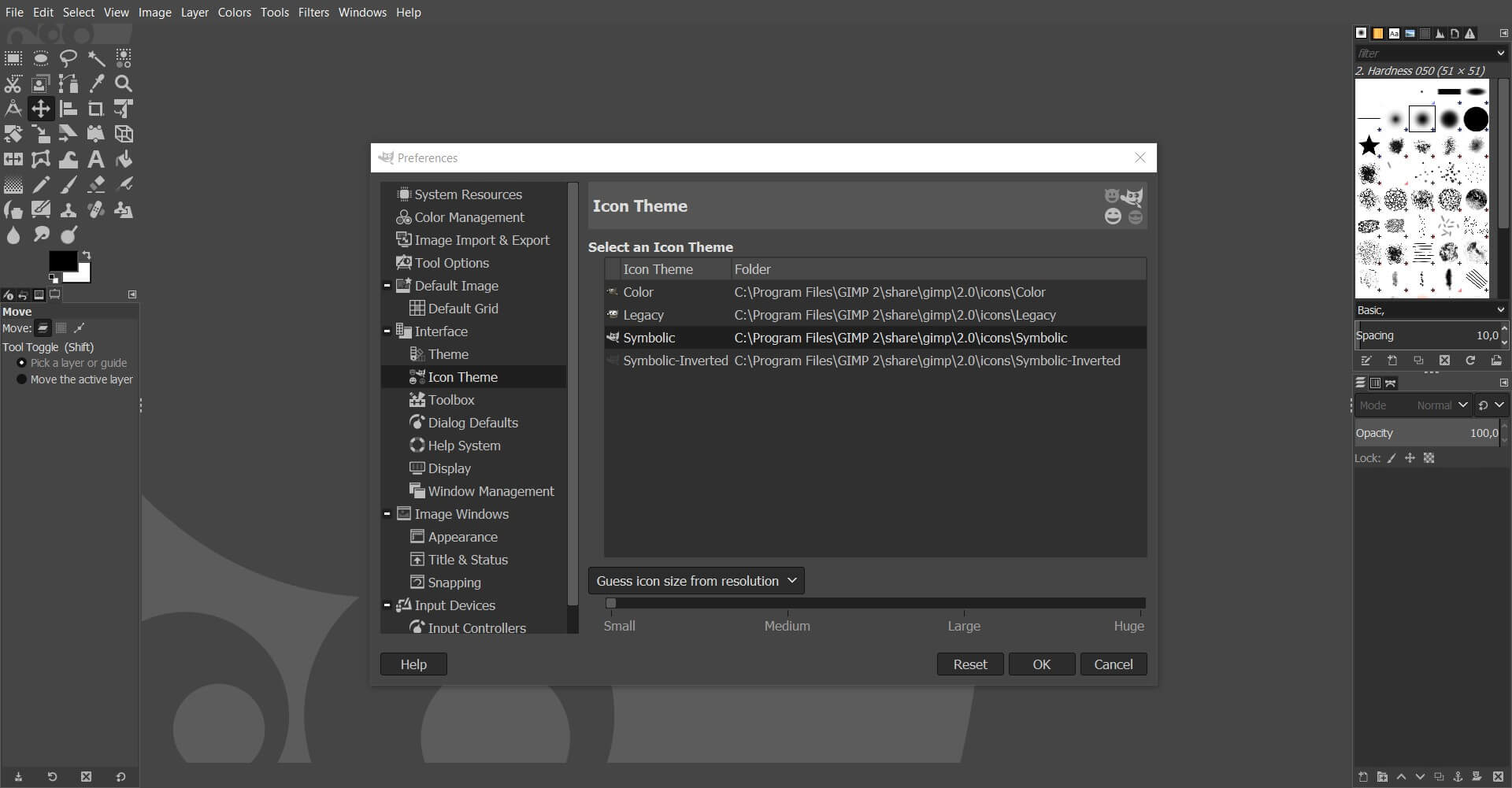
Starting to use Gimp gives me the feeling of being a less polished tool. The menus, the layout or even the logo don’t feel as professional as others, but I quickly find everything is fully customizable so you can leave your workspace like the one you used in another enviroment. Menus and toolbars can be easily moved around just by dragging and you can set the most suitables tools for your needs in the tab Windows > Dockable Dialogs. The aesthetics can be modified in Edit > Preferences > Interface and many other deep custom changes.
Although all these options allow you to have an environment configured to your liking, in our case the default interface is quite unintuitive, and to start working with an image it is better to resort to a tutorial for beginners. I leave Gimp’s own tutorial page referenced but on YouTube we can also find a large amount of content on the use of the program. After some learning I have managed to use some of the selection tools and learned to easily handle the layers and their operation. I have ventured to do a mischief, emulating what my collegue Mauro has done.
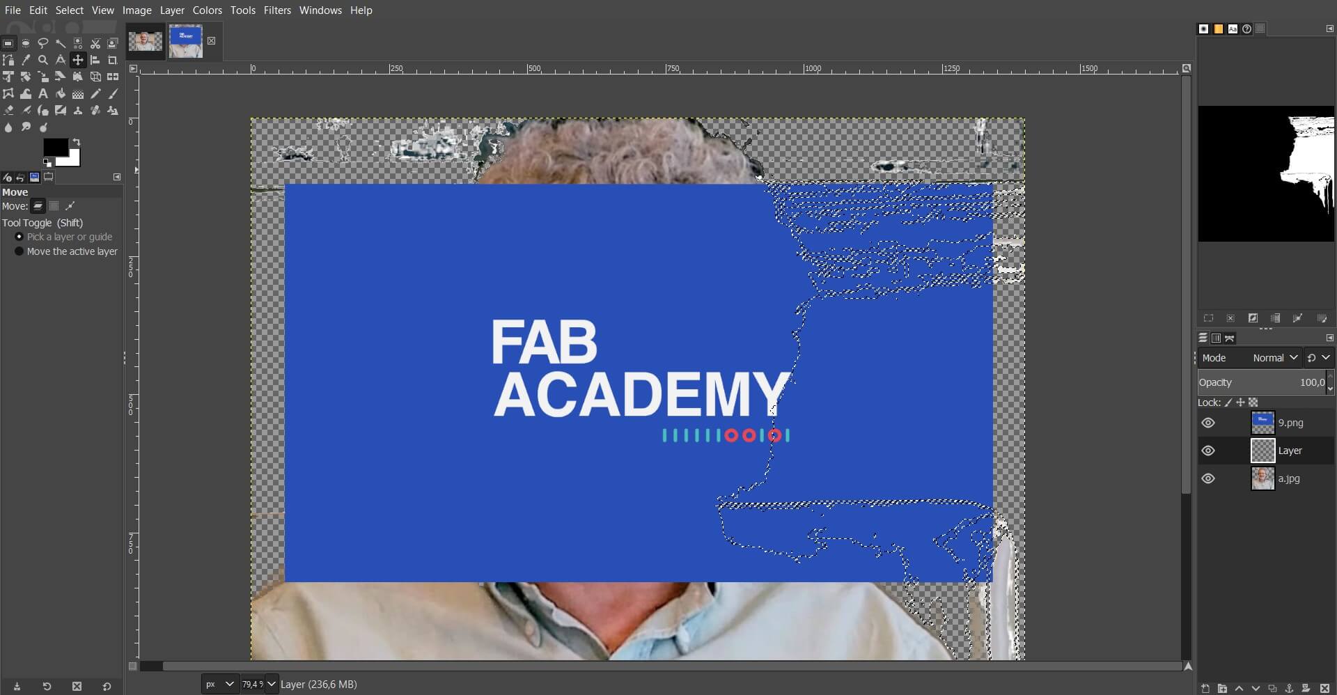
I have taken the confidence to make a small collage with an image I found online of our mentor and the course logo. Using the Fuzzy Select Tool I’ve managed to remove the background of Neil’s image, to leave just the subject. We can also do this by manually tracing an outline of the border and the removing the outter part, but it takes much longer. This tool gives you a great results when the colour of the regions you want to select dispair with the ones in the rest of the image. To correct the glitches made by removing unwanted parts I have used the Healing Tool. Later it’s just a matter of using different layers for each image and using Transparency settings for the one with the logo.
I have not considered the framing or style of this “creation” so I will choose aleatory values. To crop it to the desired size you can use Layer Boundary Size to set the dimensions of each layer, and the content will crop accordingly to this dimensions. Then use Fit Canvas to Layers and the image is ready to export. You can also scale the layer if you want to keep all of it’s content or set the Canvas Size first and then Crop to Content. This is the end result:

Working with Gimp has been mostly a great experience and has opened my mind about free software. Although it doesn’t look visually as polished as other professional tools, the functionality and it’s capabilities are amazing. The image itself has no intention of generating mockery, it just seemed like a fun idea to experiment with the program and I found it fun to share. Hope you like it Neil! 
Inkscape⚓︎
Inkscape is a free software tool focused on editing vector graphics. As between Photoshop and Gimp, inkscape is presented as an alternative to illustrator, and the experience is not far from the professional tool of Adobe. Having used Illustrator before, getting started with Inkscape has seemed a bit more intuitive and straightforward.
My goal with this tool is to make a new favicon.svg for my website. The Fab Foundation logo seems the most appropriate to me since it is also the one that appears by default if we do not define one in particular. Even so, my intention is to make a single one composed of the stroke, without colors. We can find it on the internet easily as a jpg image with a more than decent resolution like this one
Once we have the image, we open inkscape and insert the file. We can drag and drop directly from the directory where you have it or import it with the import bitmap or svg image tool. When inserting the image allows you to configure some parameters with which to treat the image, but in this case we will only need to make sure to embed it and not link it. Now we just have to click on the image, and use Path > Trace Bitmap which is available on the top tabs.
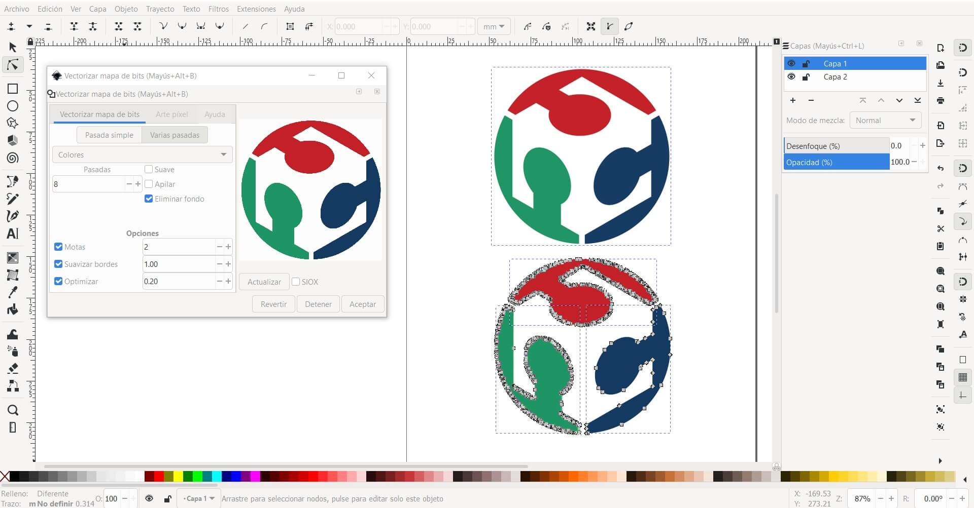
A dialog box appears with different scanning and plotting options, which notably change the result we can obtain. First of all, we must select the image directly on the canvas and then modify the settings as we believe that they better fit the image we have and the result we want to obtain. In my case, with the intention of being as precise as possible, I have increased the precision levels (optimize) of the tool and reduced the rounding (smooth edges). The result is a vector with too many control points for how simple the image is.
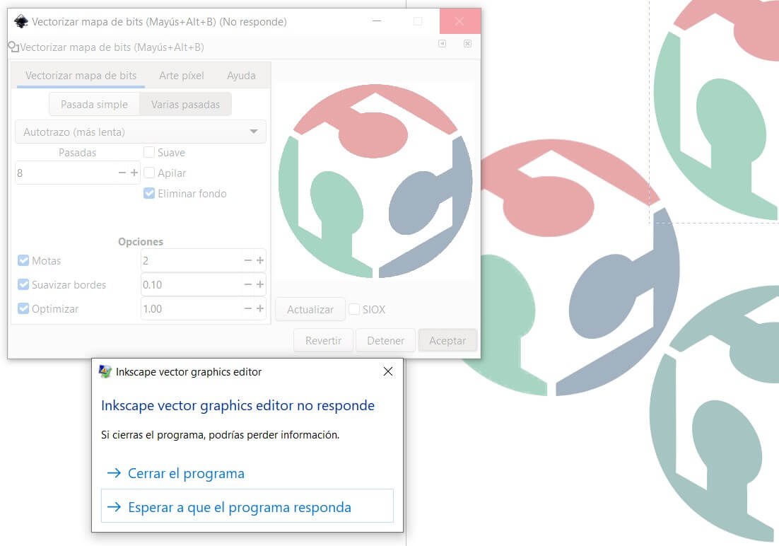
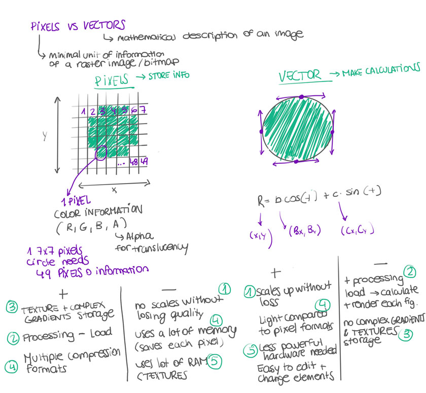
Tweaking these parameters is key to obtaining a good result. Complex images may need many more control points to draw the necessary contours, but with such a simple logo it is more advisable to have many fewer control points but greater precision in the line, since they are mostly straight lines. More control points means more vectors and vectors are the mathematical description of that image, so it can end up making the image a very complex element to process. It took me a while to realize this so in the making Inkscape got a little overwhelmed and crashed twice. So i had to start all over again. 
After encountering these problems, I have been curious to delve a little deeper into the differences between raster images and vector images. Coincidentally during the regional review a colleague from FabLab Barcelona, Carla Molins, showed some drawings in which she synthesized amazingly these concepts: Pixels vs Vectors. If we zoom in on the canvas enough and compare the edges of both images, we can see the difference between the inserted image of the .jpg logo, which appears in red, and the result of vectorizing it to .svg in black.
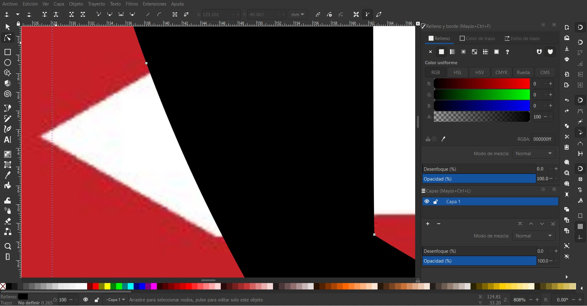
The difference between the vectorized image and the raster image is evident at that scale but it is not always more convenient to use one of the raster images. Its scalability without loss, because it is a mathematical equation and not a bitmap, is very useful for large format elements and they are also great allies for simple images. Even so, the detail that a photograph can cover would be immeasurable for a vector map, so it is necessary to use each one for its function.
These are the final .svg files I have pulled out. My intention is to use the logo with a fine line for the thumbnail of the navigator and the one with a thick line for my website. I will document the process of changing this elements in Markdown at the Project Management assignment.


3D⚓︎
3D design is a playground for me. One of my greatest diversions when I started using the computer was playing “The Sims” to model houses with all kinds of shapes, cantilevers and blocks, to the point that I learned to install mods to get more interesting models. When I first started learning rhinoceros, my main modeling tool today, I really enjoyed the process. For me modeling in 3d is absorbing, so I hope I don’t get lost all week with these tools!
Fusion 360⚓︎
Fusion 360 has been a program that I have installed on at least three different computers, about which I have read, seen tutorials, but which I have never finished delving into. The few times that I have decided to start it, I have found a very different design methodology compared to my main tool, Rhinoceros.
There is no specific reason, but I find the design process unintuitive in this type of program (the same thing happens with Freecad). Even so, I recognize that starting from a sketch and being able to model in reference to it allows to be more precise and to be able to modify aspects of the design afterwards, without having to go back in time. That is why I am going to start using it using the sample files provided by the program, to pave the first part of the way.
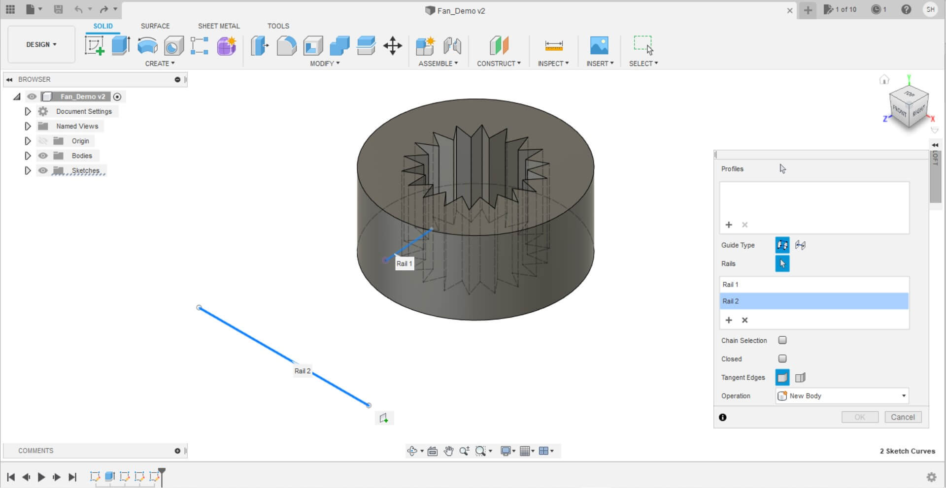
Already in the first operation, just trying to join two curves using the loft command, it doesn’t let me complete the action. After lots of errors and trying to understand why, it turns out that Fusion uses the same command without specifying for what type of element we are going to use it, which you have to designate and it does not ask you for it. I think this is gonna be too tedious. I followed this tutorial as a guideline to don’t get lost in the making. After several attemps, being unable to scale the blade and getting crazy finding the correct tools, I finally finished my “submarine propeller” fan design!
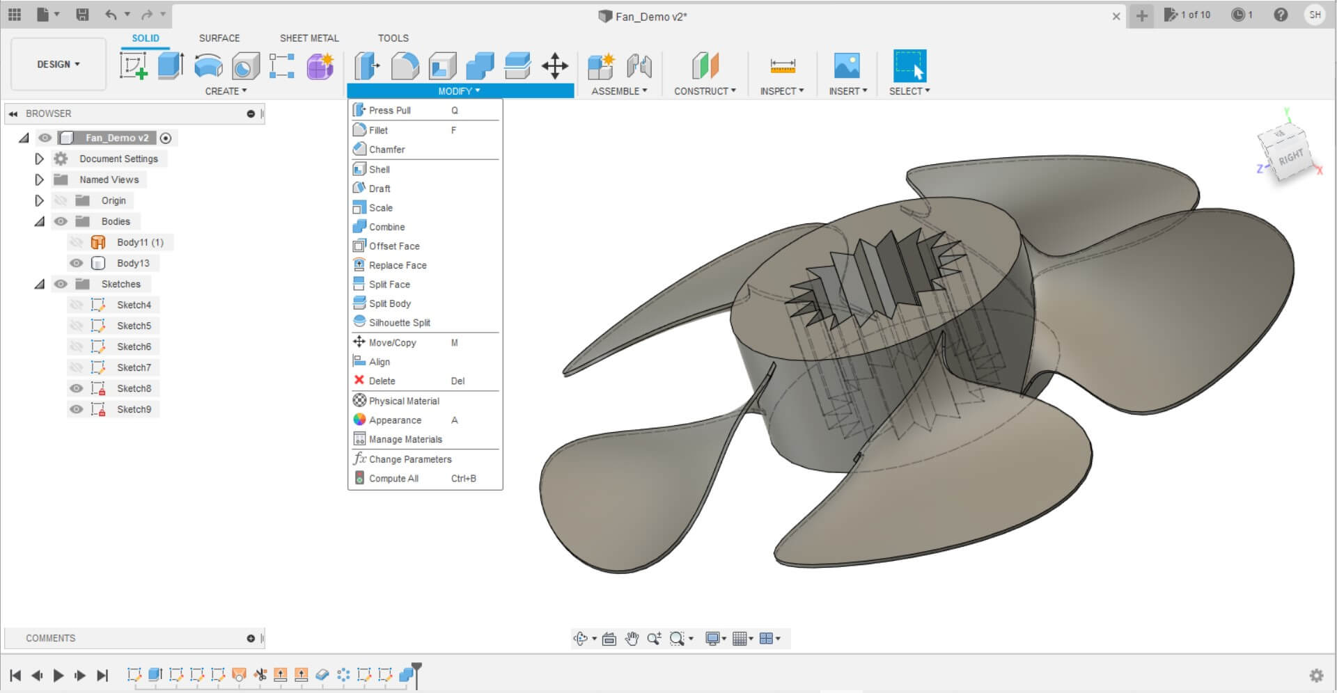
Despite everything, it has been a very interesting experience. I was very surprised by how flexible the design becomes when you can go back and forth in the design with the timeline, and how the final shape varies by changing elements from the beginning. I also liked the management of the layers that fusion does, as it divides it according to a sketch, the main body or other elements. It makes it very easy to work on specific elements of the design without getting confused with the whole piece.
Even so it has not left me a good feeling. The interface still seems very unintuitive to me, and the workflow becomes very tedious if you do not know well the way in which the fusion tools are organized. I suppose that with time it will get easier, so I will try to continue using it when I have the opportunity.
Rhinoceros⚓︎
Rhinoceros 6 is currently my default 3d modeling program. It has been one of the tools in which I have been most instructed, due to its powerful mesh tool, which we used a lot for geometry exercises. It is a software in which I feel very comfortable and I would like to continue learning 3d modeling. Some plugins such as V-Ray or Grasshopper for parametrization are very powerful and I would like to achieve a good handling of them, but I don’t think I will have time this week for them.
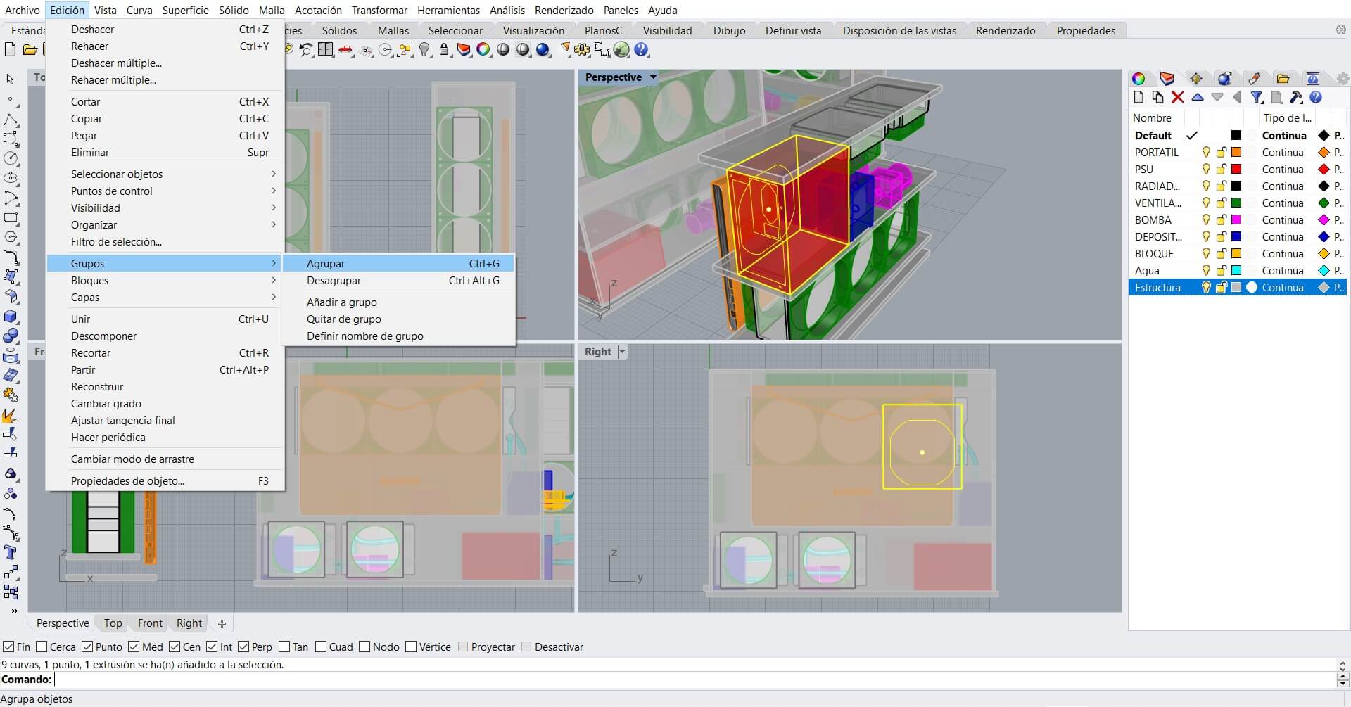
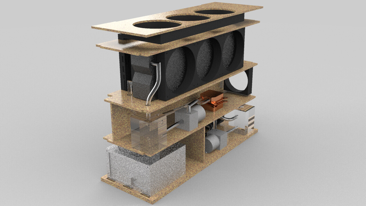
Since I have not yet specified what my final project will be, and I had already been modeling one of the ideas proposed in Principles and Practices, I have decided to move forward with the design process and do some renderings with different materials. Some of the problems that I have had designing with Rhino is that, unlike Fusion 360, which has an exclusive tool for sketches and that you can visualize or hide, there are many auxiliary lines that do not belong to the solid and that in many cases they can create confusion in the design. Normally, having a separate layer where we use all our auxiliary curves is enough, but recently I have started to include some of these lines to the part design because they are useful to me during other processes. With the group command they remain integrated into the solid.
In many cases, when I design in rhinoceros and in this project with more reason, I leave different versions of the previous model in case I need to go back to any of them because I have dragged a design error or simply wanted to try different configurations with the same solids, such as is the case. When designing the laptop dock, I have changed the layout of the designs several times as I realize what is the best layout for optimal performance.
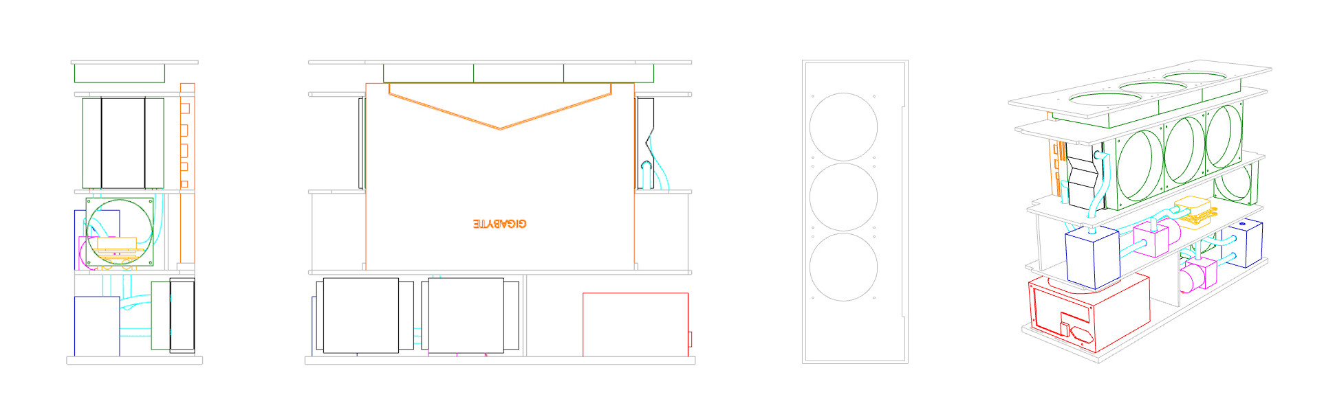
A very useful command is 2D drawing. It allows you to leave the 4 basic views of the model on a sheet. I used it frequently in architectural sheets and avoided wasting time projecting lines to make sections. This is a quick representation but you can choose the parameters of the draw, as showing hidden lines, the views, etc. This is a quick show of it’s capabilities:
To model the tubes for the water loop I have found the pipe comand, which I haven’t used before. It’s as simple as its name suggests, although it has many configuration options, such as specifying different diameters at different distances of the pipe, the thickness of it, the type of cap, etc. A polyline is necessary on which to guide the pipe.
After all the modeling involved, my instructor Adrian recommended me to upload the model to a platform called SketchFab, so it can be embedded on the web to interact with it. Sadly this site doesn’t support .3dm, the standard file from Rhino, and needs to be uploaded as an .stl, so all the layers and solid configuration are lost. Even so, I will leave the original Rhino file at the end of the documentation.
I also want to highlight a problem I have been having when exporting or importing 3D models from other file formats: surfaces as meshes (polygons) or nurbs. Rhino it’s a powerfull 3D tool that includes these types of surface modelling and I don’t know which one is better for what and why, so I made some research. This article makes some solid statements about when to use each one.
It is the turn to give a more real appearance to the model, but rendering in Rhino is quite unknown for me. I hardly know techniques or key elements to take into account to obtain the most realistic possible result. The first step is to characterize the solids by designating them a material. Since the design has pieces of almost all materials, I will try different finishes and types to see what result each one produces.
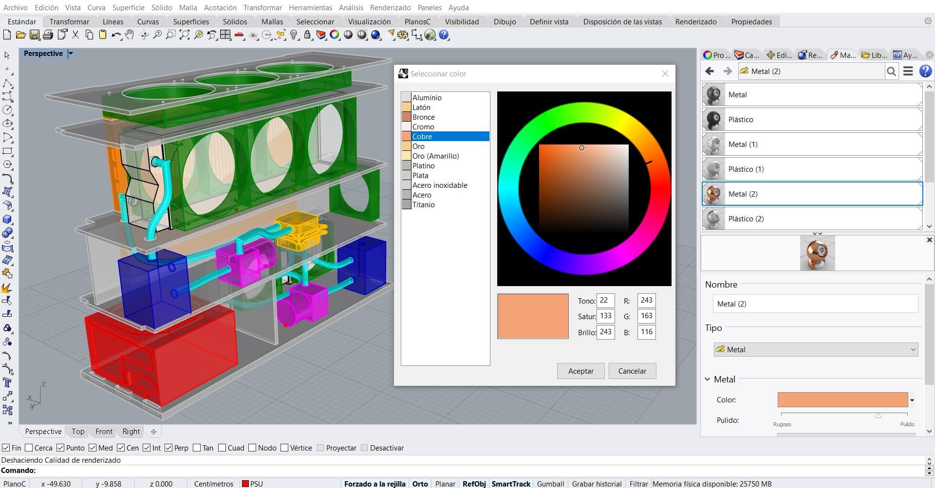
Materials are highly configurable, from texture, appearance, gloss, or reflectivity to the degree of light absorption. It is clearly beyond my knowledge so many of these settings will remain by default as they are preset by the material. The library of materials is huge, having to choose for example between more than 100 types of woods.
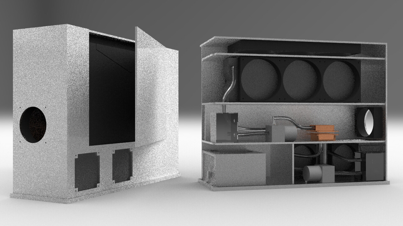
Choosing the correct quality for rendering in Rhino is another key point. Good quality renders make the computer work as it was runnig 35 marathons in a row, so it is advisable to try first with the lowest quality and resolution settings to make sure that the frame, the view and the materials that we have selected, look as planned. After doing 3 different views and some material changes, these are the ones that have convinced me the most:
After all these processes I have decided to design the fan model that I have bought for the project. The intention is to compare the design time and process between Fusion and Rhino. Obviously my fluency here is going to be greater, but since I have very recent Fusion processes, I am interested to know if I could benefit more from the workflow of the other program with the appropriate fluency. In Rhino, the design of objects with non-planar surfaces is carried out through a geometric development, since editing solids through surfaces is much more complicated and gives many errors. I also intend to add the design to the model, since it has given me the impression in the renders that the use of ventilation is not understood as it is only the designed frame. This is the timelapse of the process:
Blender⚓︎
As for this week we have to try and get into any animation tool, and since Blender in addition to being a powerful animation software, it is also a 3D design tool that I wanted to learn, I will take the opportunity to get started in it. Despite of being open source, this program is a pretty powerfull tool, and many professional work can be done with it. Because of that, it’s also too complex to get rolling without mentorship so I will search for some help.
So far I have not handled any animation program, but from what i’ve seen it looks pretty funny. Obviously it is a very complex process but in my case I am just going to get into the technique and try some tools. I was trying to follow this tutorial but it skips some steps because it’s not beginner oriented so I got a bit lost. I was trying to replicate the sequence he makes but I’m not even close enough. At least I got the cube repeating the movement path I made, so it’s technically “animated”.
Since I haven’t got more time for this week I couldn’t make any better animation but this are the tools I learned:
- Auto Keying: Auto Keyframe is the circular record button located at the bottom center in the Timeline header. Auto Keyframe adds keyframes automatically to the set frame if the value for transform type properties changes.
Space: it’s used to start recording the sequence. Also I noticed later that the duration of the “film” is preconfigured by the number of frames that are already set, so you can’t just press space to start and then press again when your over.G: let us grab the object we designed so then we can use the mouse to move it around.Shift+F6: it opens the graph editor, where the recorded movement is displayed by frames. This let us edit the movement we just recorded to make it smoother and realistc. I tried to edit mine as you can see in the photo below.- Vertical split: if we want to have more than the 3D space open at once to merge tools or see the result while making the changes, we can use this feature. To activate it just right in the border of the window when the resize cursor appears.

As I said before, it’s a complex tool and I have gotten a bit overwhelmed trying to learn it. Probably because I have chosen not the right tutorial. Some of my collegues have been able to produce pretty cool work, so I will try to get back to it in the future when I have some free time, because despite the trouble, looks like an awesome tool.
Conclusions⚓︎
This week has been quite a busy one. It has been my first week here at Leon, getting to know new places and adapting to new rythms. It’s the first time since the pandemic hit in 2020 that I really feel I’m doing something different, and it’s quite refreshing. It hasn’t been easy.
Some ideas got clear in my head while working this week about what I need to improve, what has helped me and what to look after.
- I have realized that consulting the objectives of the assessment corresponding to the week and writing them on the page helps me to specify during the week.
- I must be careful and try not to drag work from previous weeks, because that has stolen several days that corresponded to the previous week, preventing me from getting all the work I wanted during this one. The more weeks that pass, accumulating that load would be unfeasible. What’s done is done this, and the following week. There will be time to improve it.
- There is no point in doing work at the tun tun. It is important to clarify the objective and find a speech to make a coherent documentation.
- The support of colleagues has been very important this week. They have been able to get much more work than me since they are in their most optimal conditions. I, however, am still adjusting to these changes. The important thing is how I feel that they have supported me and how the unity of the group has allowed me to advance better. Despite each being in a Lab and not in person, the online and group meetings are working very well.


Files⚓︎
- Logo Fab Original(
.svg): file - Logo Fab main color(
.svg): file - Logo Fab thin line(
.svg): file - Logo Fab thick line(
.svg): file - Submarine propeler(
.f3d): file - Submarine propeler(
.stl): file - Laptop dock(
.stl): file - Laptop dock(
.3dm): file - Blender animation cube project(
.blend): file