Week13
Networking and communications
Group assignment
send a message between two projects
Individual assignment
design, build, and connect wired or wireless node(s) with network or bus addresses
To start this assignment, we all did a quick and simple exercice in order to understand better how networking works with arduino on Tinkercad, here is the tutorial
In this tutorial the "master" board provides the power (5v and GND) to the "workers" and send a message to them by specifying names/addresses (a,b,c,d or e, in my case). Each indivudual nodes listen for his name/address in the message and apply its task if his name is stated.
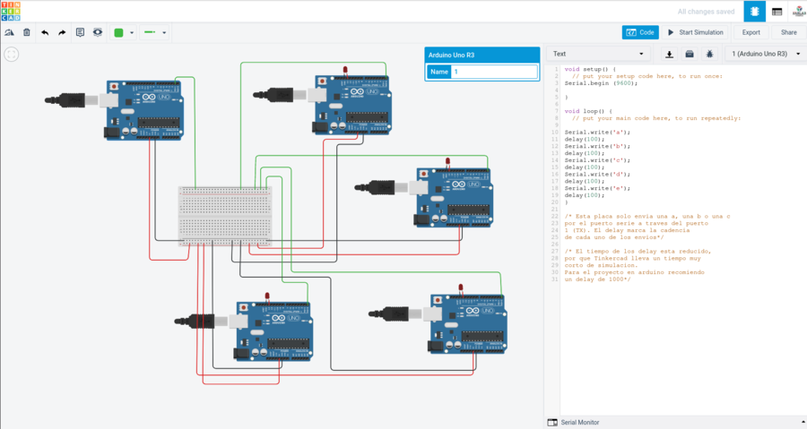
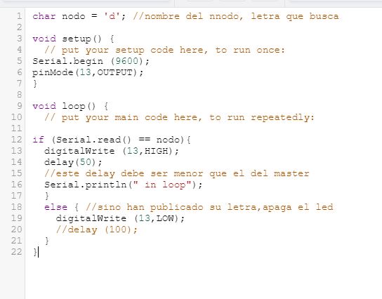
Now with the boards produced in the previous weeks, in week10 the step reponse will be my input device (final project) and it will be the "master" (bossman), in week6 the hello board as a node with LED as an output and from week12 the output device board with motors and power supply.
Here is a usefull link, I also had a look at theses docs; Nikhikumar, Toshiki, Tiago and Katerina.
I joinned the Global open time reunion to find out more, here is what we discuse during the session...
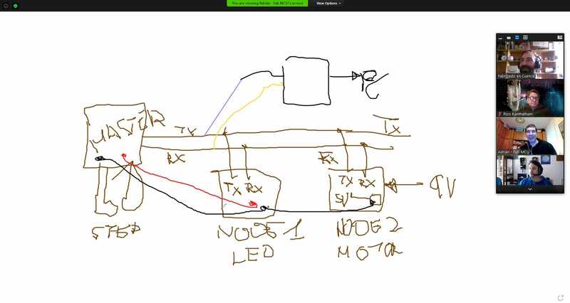
And a usefull video explaning the different types of network communications.
I am going to try a simple code first and blink leds, the attiny412 board (week10) will send a call to the nodes ("a" and "b") with the following code
							void setup() {
								// put your setup code here, to run once:
							  Serial.begin (9600);

							  }

							  void loop() {
								// put your main code here, to run repeatedly:

							  Serial.write('a');
							  delay(100);
							  Serial.write('b');
							  delay(100);
							  }
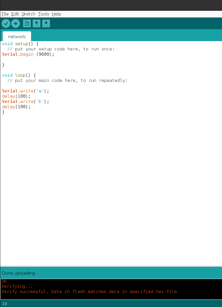
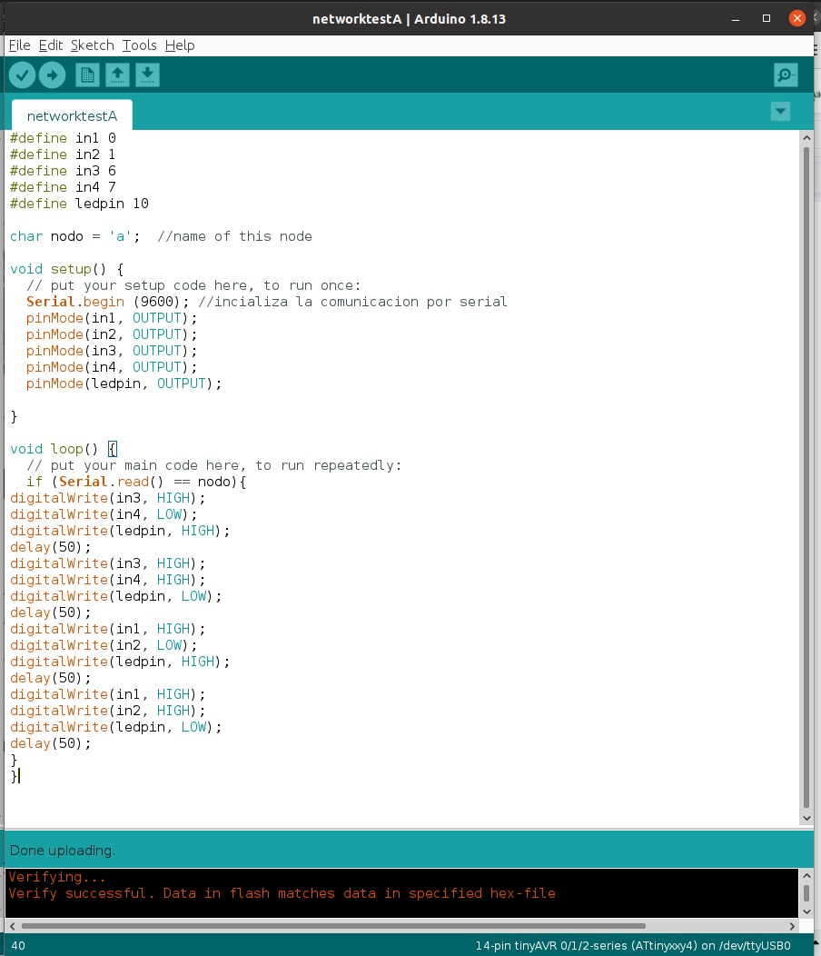
The attiny1614 board (week12) will be node "a" and will blink the onboard LED for now (I am using the same code used that week but I disconected the motors for this test).
								#define in1 0
								#define in2 1
								#define in3 6
								#define in4 7
								#define ledpin 10

								char nodo = 'a';  //name of this node

								void setup() {
								  // put your setup code here, to run once:
								  Serial.begin (9600); //incializa la comunicacion por serial
								  pinMode(in1, OUTPUT);
								  pinMode(in2, OUTPUT);
								  pinMode(in3, OUTPUT);
								  pinMode(in4, OUTPUT);
								  pinMode(ledpin, OUTPUT);

								}

								void loop() {
								  // put your main code here, to run repeatedly:
								  if (Serial.read() == nodo){
								digitalWrite(in3, HIGH);
								digitalWrite(in4, LOW);
								digitalWrite(ledpin, HIGH);
								delay(50);
								digitalWrite(in3, HIGH);
								digitalWrite(in4, HIGH);
								digitalWrite(ledpin, LOW);
								delay(50);
								digitalWrite(in1, HIGH);
								digitalWrite(in2, LOW);
								digitalWrite(ledpin, HIGH);
								delay(50);
								digitalWrite(in1, HIGH);
								digitalWrite(in2, HIGH);
								digitalWrite(ledpin, LOW);
								delay(50);
								}
								}
And the attiny45 board (week6) will be node "b" and will also blink its led...
								#include
								#define Rx 1
								#define Tx 2
								char nodo = 'b'; //name of this node
								int ledpin = 4; //attiny 45 ledpin
								SoftwareSerial MyfirstSerial(Rx,Tx);
								// the setup function runs once when you press reset or power the board
								void setup() {
								MyfirstSerial.begin (9600);
								pinMode(ledpin, OUTPUT);  // initialize digital pin LED_BUILTIN as an output.
								}

								// the loop function runs over and over again forever
								void loop() {
									if (MyfirstSerial.read() == nodo){ //if your name is in the serial...
									digitalWrite(ledpin, HIGH);   // turn the LED on
									delay(50);                       // wait
									digitalWrite(ledpin, LOW);    // turn the LED off
									delay(50);                       // wait
									}
								}
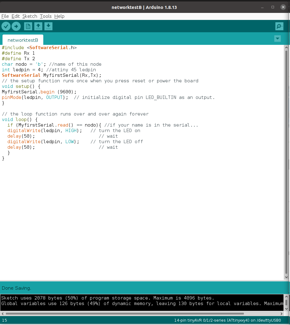
To be able to use the Attiny45, I found this usefull documentation as well as here and here. With the information find there, I was able to figure out how to asign the Tx and Rx pin using softwareserial communication (see code above).
I then conected the 3 boards together as shown below (I made a quick jumper cable). I went through each week´s documentation to make sure to conect the boards the right way...
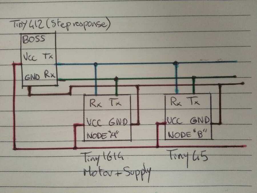
GND is commun to all boards, as well as VCC (node "a" will provide the 5v from the external 9v batery through its regulator to the other boards), the Tx from the "master" will go to the Rx of the nodes and Rx (Bossman) to the Tx (workers/nodes). I conected the hello board from week6 through the x6 pin header normally used for programing.
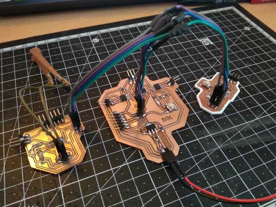
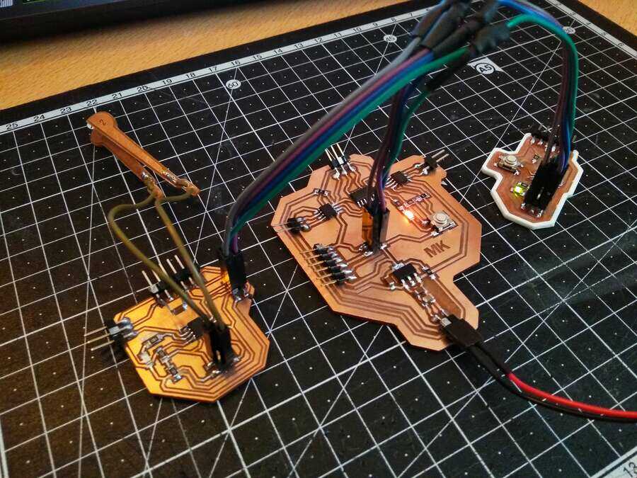
first time I switch the power on, only node "a" was active but once I change and swap the TX and Rx of node"b" (made a mistake conecting them), everything started working fine...Now with the motors, I am also taking this oportunity to measure the power consumption of the setup since I was not able to do that for last week´s group assignment.
Just LEDs and with motors...
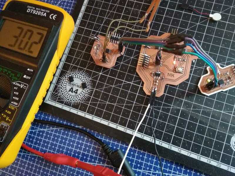
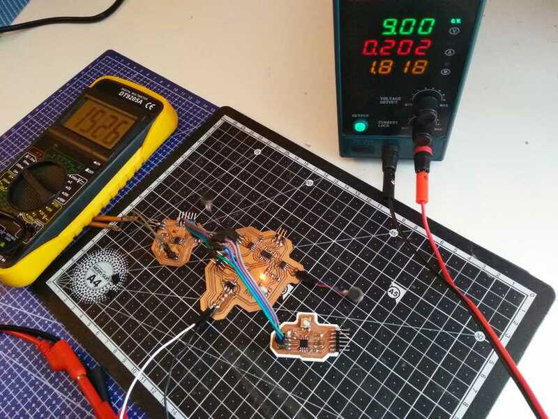
We got a little logic analizer, as advised by the instructors so I have done the first test to see if I was able to used it.
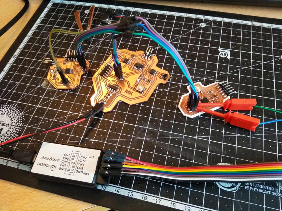
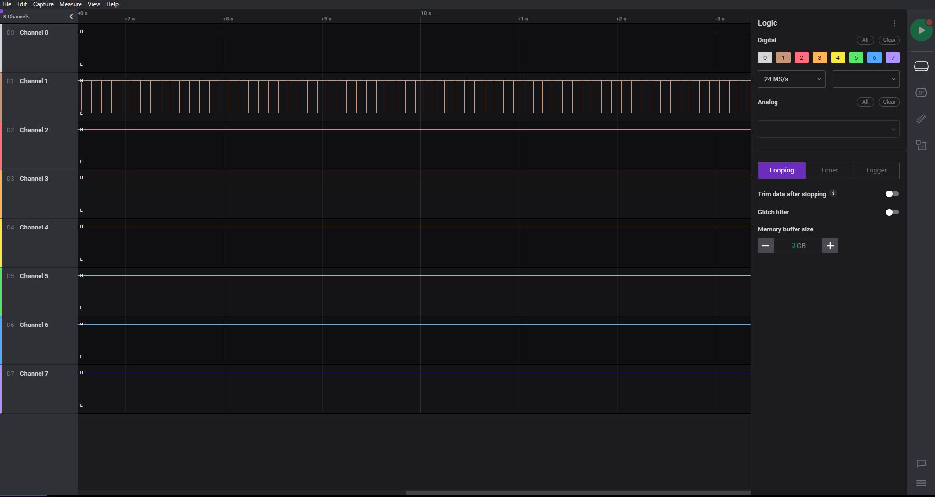
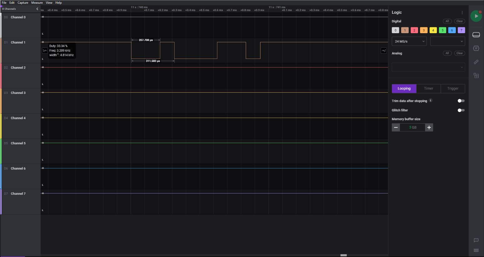
I am seeing one signal, which should be the one coming from the "bossman" (master) going to the nodes "a" and "b".
I have also worked on the final project, I tested an other type of silicon (week11) and 3D printed a small part of the brain model to do some tests on the best way to post-process the print and get a smoother mold (Development).
Learning outcomes
Demonstrate workflows used in network designImplement and interpret networking protocols and/or communication protocols
Have you?
Linked to the group assignment pageDocumented your projectDocumented what you have learned from implementing networking and/or communication protocols.Explained the programming process/es you used.Outlined problems and how you fixed themIncluded design files (or linked to where they are located if you are using a board you have designed and fabricated earlier) and original code.
Key Learnings
- The DFPlayer Mini shares the serial bus and causes conflicts — the DFPlayer Mini MP3 module uses serial communication on the same pins as the UART network. This caused bus conflicts that corrupted commands to other nodes. Solution: use SoftwareSerial to assign the DFPlayer to a dedicated pair of pins separate from the main UART bus.
- Only one device should be the bus master — in a UART network, having multiple nodes trying to transmit simultaneously corrupts the data. Designate one master node that initiates all communication and have all other nodes respond only when addressed.
- Add pull-up resistors on UART lines — floating UART lines pick up noise and generate phantom commands. A 10kΩ pull-up resistor on the RX line of each node prevents spurious triggering when the bus is idle.
- Test each node individually before connecting them to the network — if one node misbehaves on the network it can bring down the entire bus. Verify each node works correctly in isolation first, then add them to the network one at a time.
- Use unique addresses for each node — define a unique address byte for each ATtiny node and have each node ignore messages not addressed to it. This is simpler to implement than a full protocol and sufficient for small networks.
- Power supply noise affects communication — motors and LEDs switching on and off create voltage spikes that corrupt serial data. Add 100nF decoupling capacitors close to each node's power pins and consider a separate power rail for motors.
- Document your protocol as you build it — even a simple custom protocol becomes hard to debug if you haven't written down what each command byte means. Keep a simple table of command bytes and their functions updated as you develop the network.
Related weeks
Week 8 - Embedded programming —
Serial communication and ATtiny programming foundations established in Week 8 were essential for building this network.
Week 10 - Input device —
Capacitive touch sensors from Week 10 were connected as input nodes in the UART network documented here.
Week 12 - Output device —
The vibration motor and LED driver board from Week 12 was connected as an output node in this network.
Week 14 - Interface and application programming —
The Processing interface built in Week 14 communicates with the ATtiny network via serial connection.
Final Project —
Full UART network integration connecting sensors, motors, LEDs and MP3 player in the brain model system.