Week8
Embedded programing
Go to:Group assignment Individual assignment
Group assignment
Compare the performance and development workflows for different microcontroller familiesDocument your work (in a group or individually)
For this assignment I am first trying the micro bits, we have it for a few years now and never got a chance...
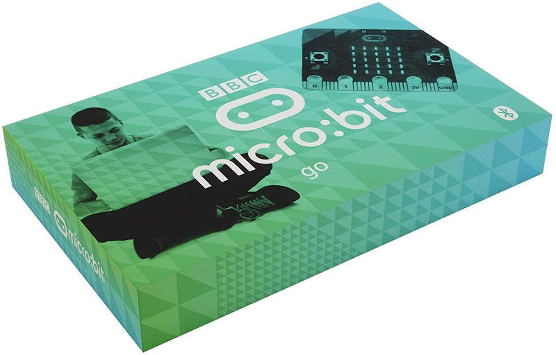
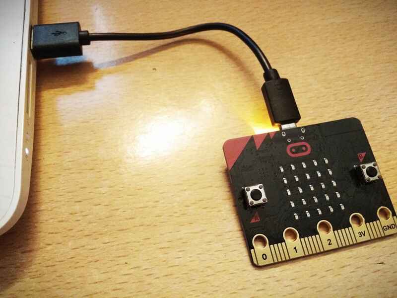
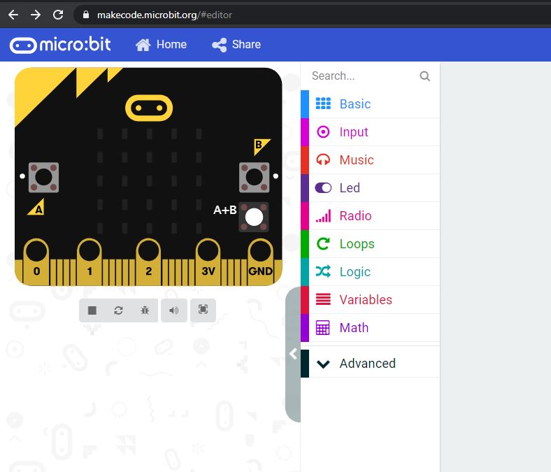
It has its own board LED array, sensors and buttons. I found information on how to get started here. To program this micro bit I use an online code editor.
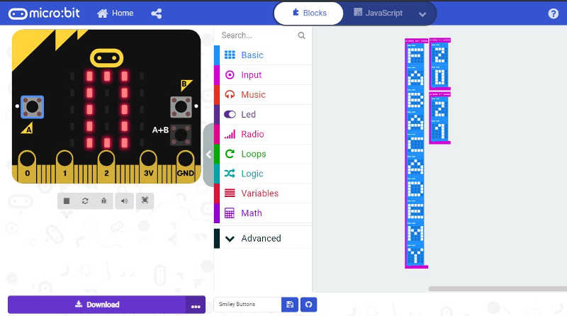
The editor works with block type of coding, similar to scratch, here is a test code...
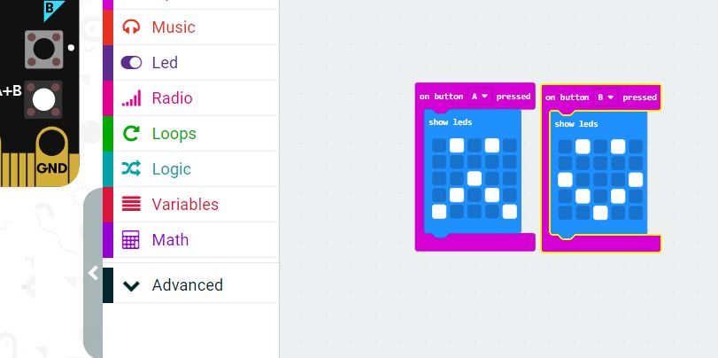
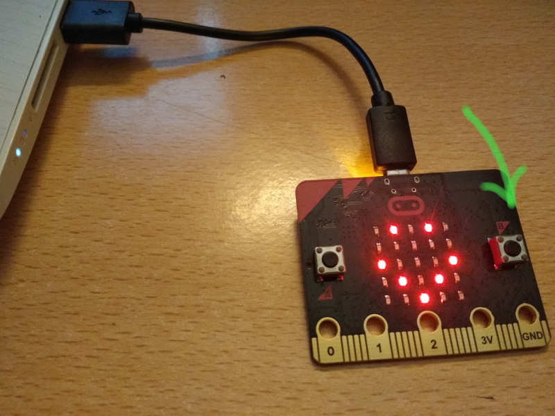
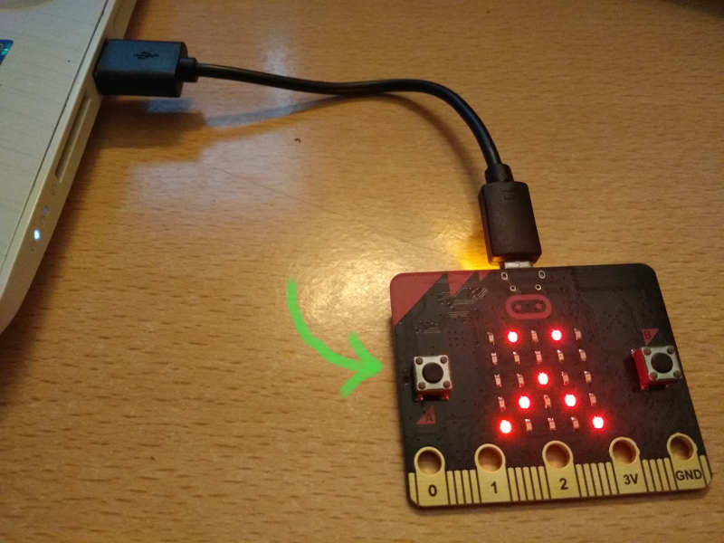
To upload the code to the board, we just need to connect it to the computer with the USB cable, dowload the .HEX file and copy it to the microbit drive (it apears in the connected USB device). The program loads and is ready to use.
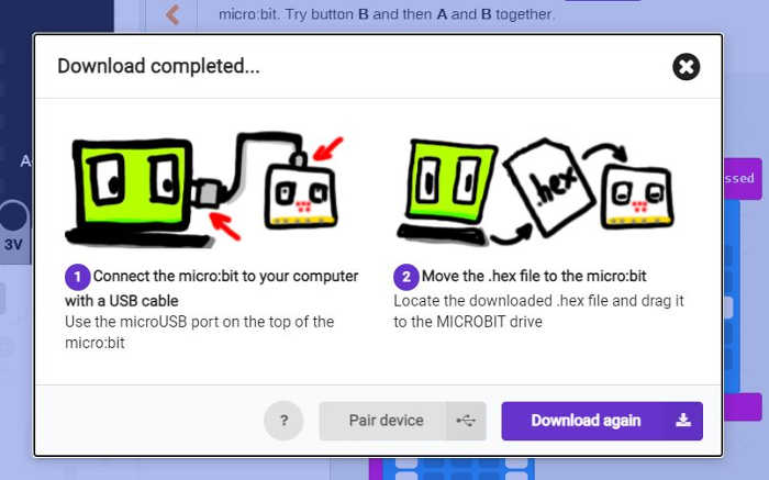
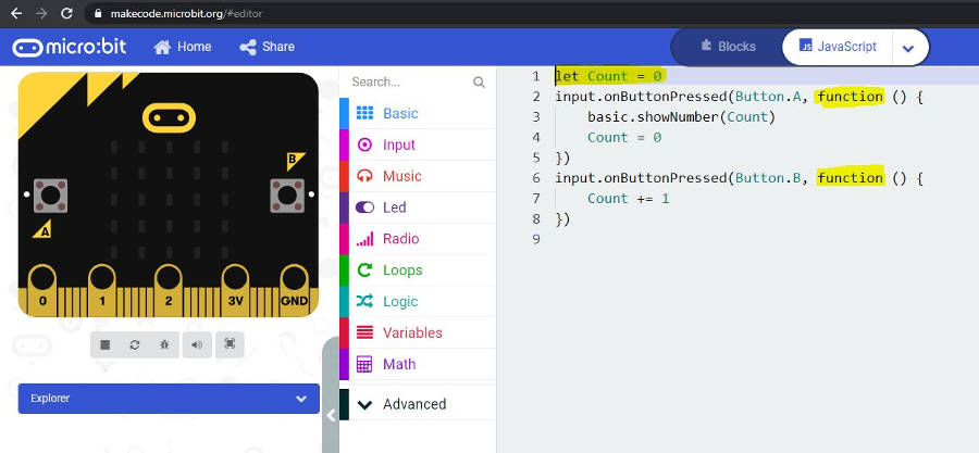
I wanted to try and see the difference between, JavaScript and Python programing language, Lorena mensionned that possibility within that same online editor.
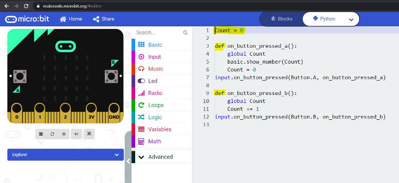
To make a simple count and display code I started by creating a variable (count) and adding 1 to it everytime button B is pushed. To display and reset the counter, I used the button A to show the number on the LED array and reset to 0.
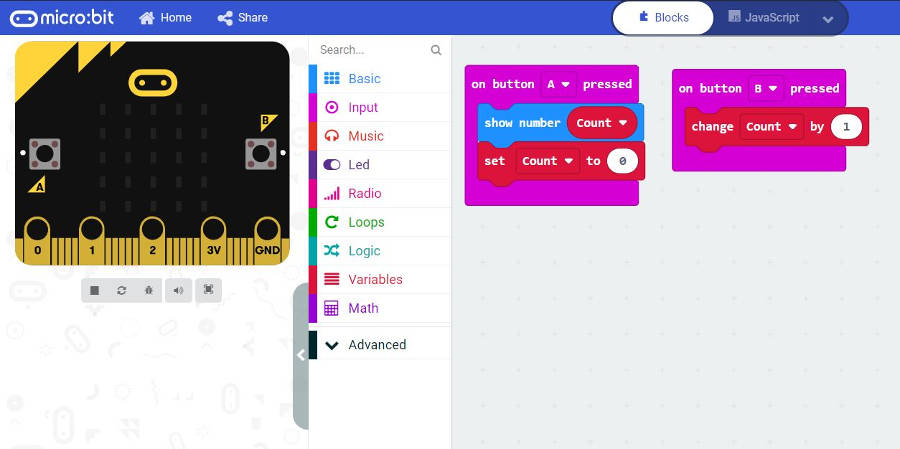
Here I can see the variable and fuctions.
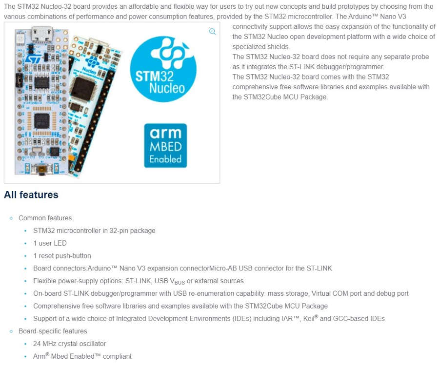
I also looked at the Nucleo 32 board, we also have that one looking at us for many years in the lab... Where I found the decription, the sofware and the datasbrief can also be dowloaded.
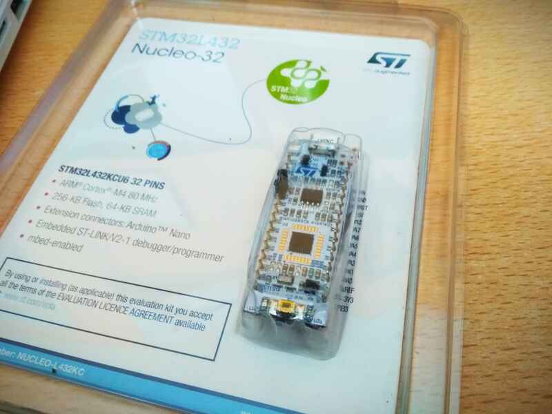
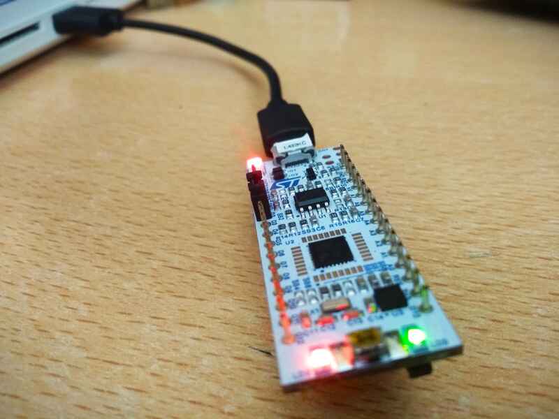
For a start, I am following this tutorial where it is used with the arduino IDE. Dowload, install the ST-link file and add the URL in the arduino preferences.

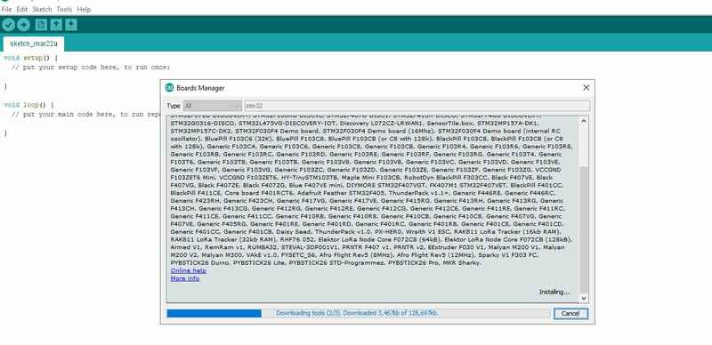
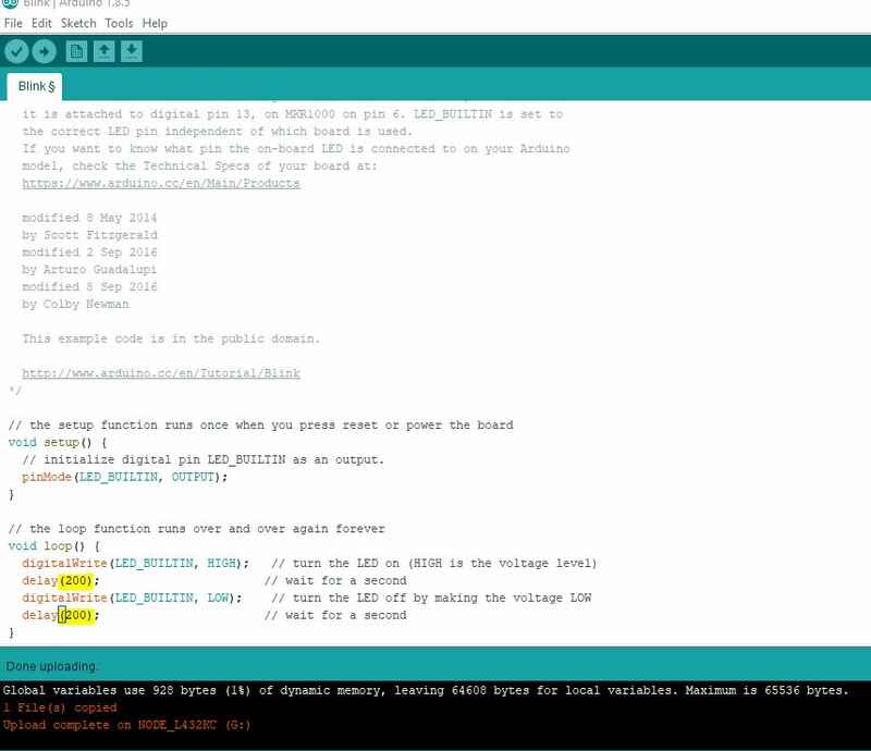
I am just going to do a blink test for now and to make sure it is running my program, I change the delay time to 200.
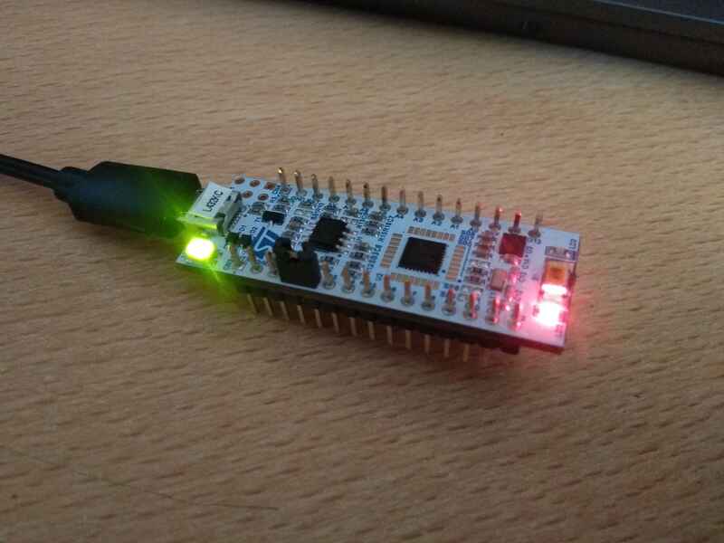
There is also this video that has a nice Introduction to this board.
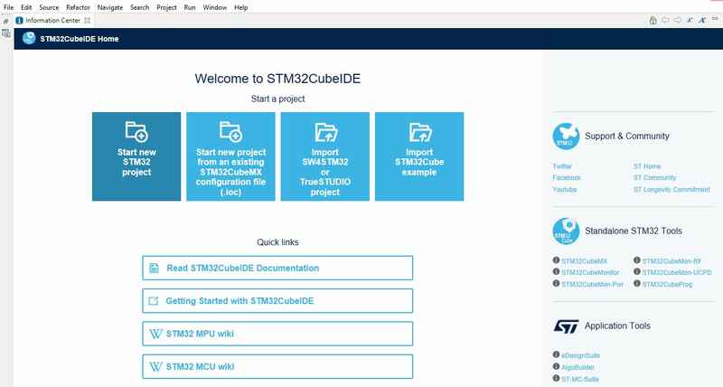
For the software, once registered, we can dowload it from the same page satated above. Let´s try the STM32CubeIDE software...after waiting for ever, I can finally start.
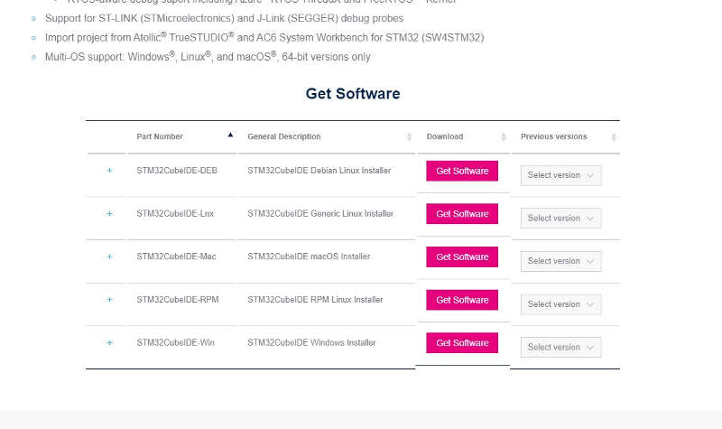

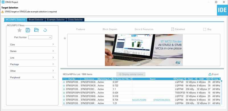
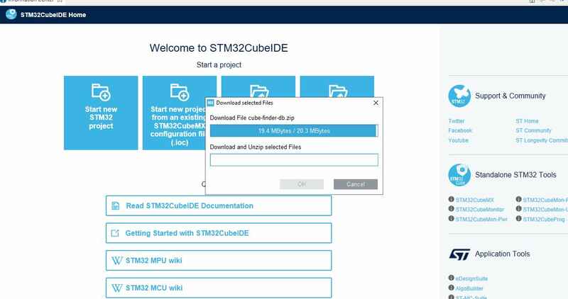
Creating a new project, selecting the board STM32L432KC and more software dowload....
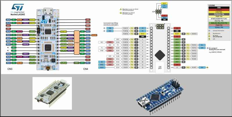
The pinout
Here I am going throught the configuration...
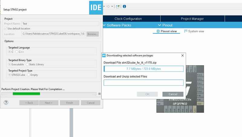
And I can start looking at the software...
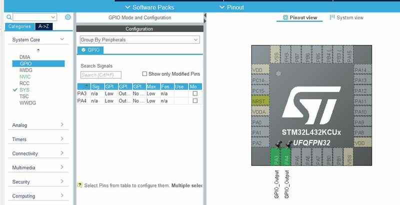
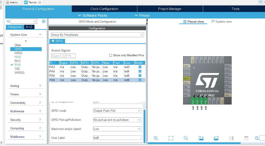
Here I can set up the pins and name (label) them, led3, led4, led5 and led6 same as in the tutorial. Although they will be used to connect to the step motor controler.
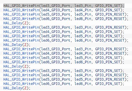
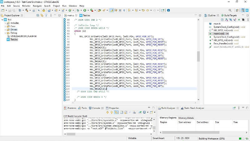
For the code, I look for the "while" section where I will add the code lines, theses lines will repeat continuously. The line works by setting the pin high or low (GPIO_PIN_SET or GPIO_PIN_RESET), assigning the port (led3_GPIO_Port) and the pin (led3_pin). Same for each pin from 3 to 6. There is also a delay that can be used to adjust the speed (2ms).
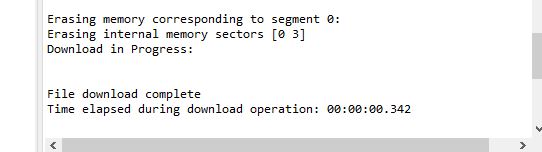
Checking the code and uploading it to the board...
I used an arduino to power (5v) the motor controler, and test the code.
Go to:Group assignment Individual assignment
Individual assignment
Read the datasheet for the microcontroller you are programmingProgram the board you have made to do something, with as many different programming languages and programming environments as possible.
Two weeks ago I got to program the board produced with the attiny45, this week I am giving a go at the attiny1614 to see if I could use it for my final project.
Here I tried to go through the datasheet...
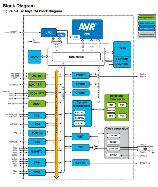
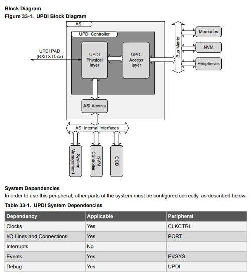
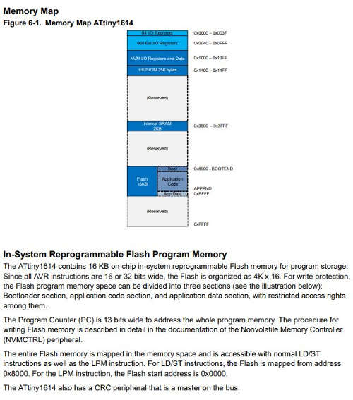
The block diagram below, explains how the microcontroller´s different elements inside interact between each other. We can also see, although I barely understand it, how the programmable memory in System is made. how it is mapped, how much space it holds, how that memory can be divided and where the detailed documentation/description on how to proceed to flash the memory can be found.
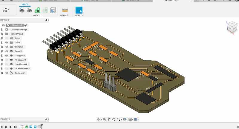
I am using Fusion 360 to design it, although I did try Kicad but the interface did not agree with me, I need to Learn the software and find the libraries...I´ll get back to it further down the line.
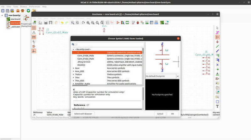
I found the attiny1614 symbole and footprint here as it was not in any of the libraries I had.
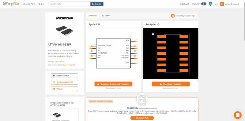
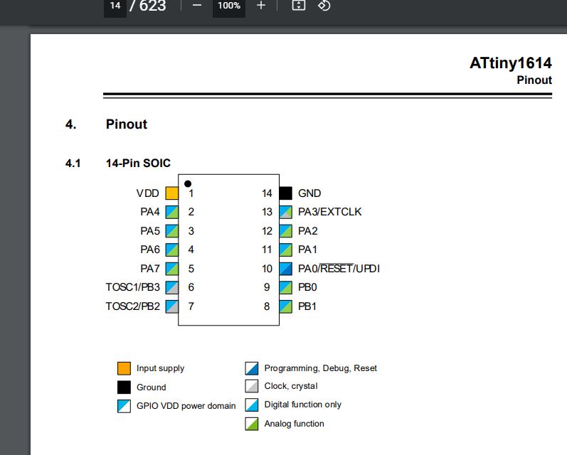
And I found the pin out in the datasheet...
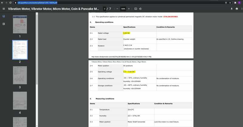
I am also looking at the motors, I would like to use for my final project and how to include one or two (x4) in this Board. I followed this tutorial, advized by Adrian and ckecked the datasheet in order to figure out the resistors values needed to drop the voltage.
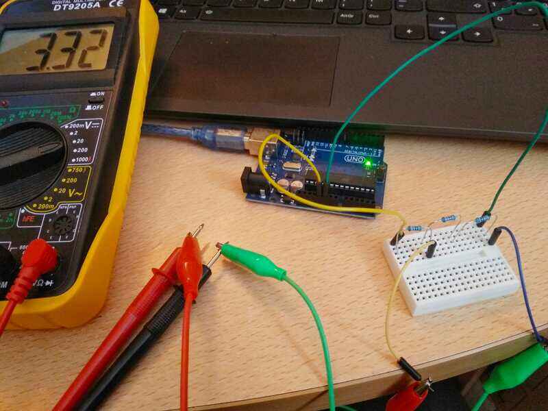
Using a step-down circuit, voltage/resistive divider, we can get from 5v to 3.3v.
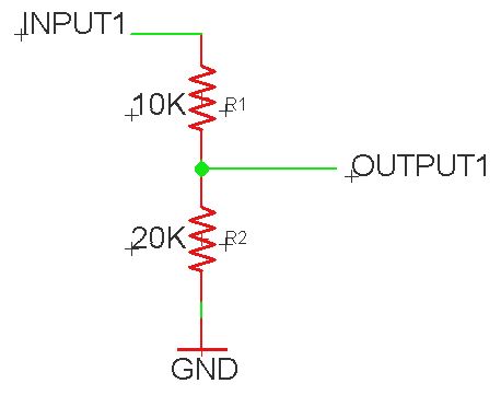
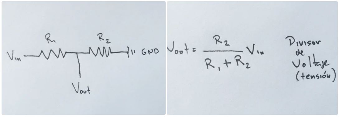
Using this formula, I will use, as in the tutorial for handiness and because I have those, x3 10k resistors, we get a voltage of 3.3v witch I guess should be fine.
I tested it with the 5v power from an arduino.
For the design, Adrian advised me and explains here, I am using the 3 pinned version of the UPDI to avoid the need for 2 FTDI to programm my board.
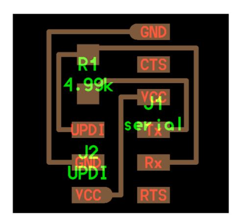
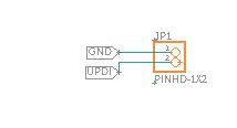
That means that I need to add a pin on my board (VCC)...
Here I made a mistake, just finishing to mill the board...I did not connect the motor´s pins to ground but to VCC instead....
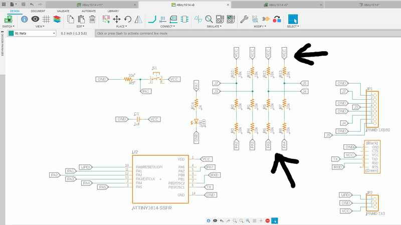
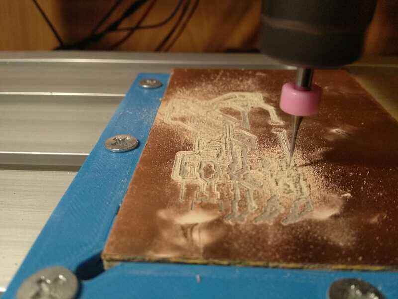
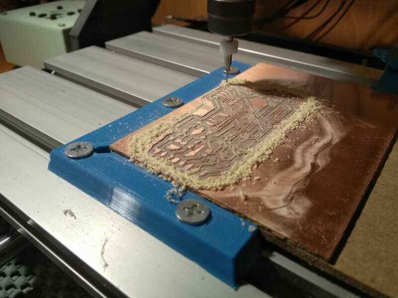
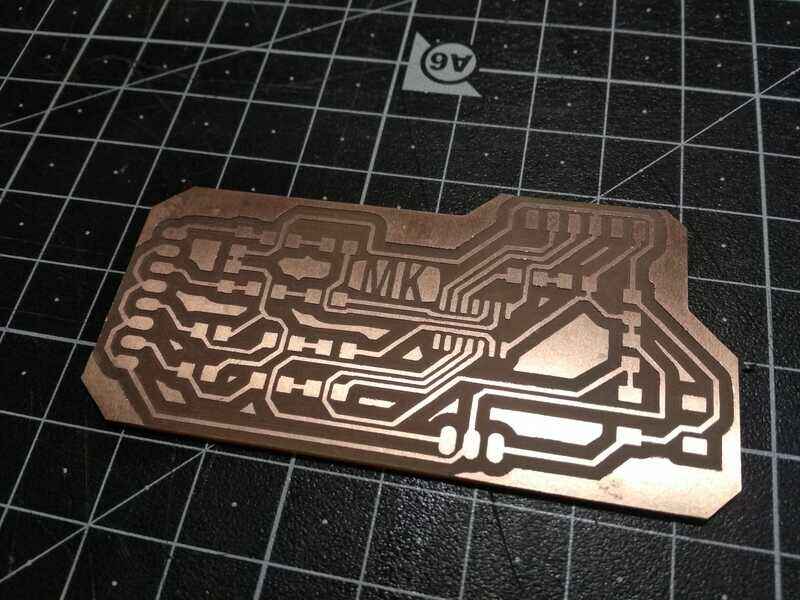
I also realized that I actually need to manually save changes by pushing "View 3d PCB" so that the very last changes are updated in all the projects documents...More about it here.
Making sure everything is synched this time...Here is the last schematic and traces, I added conection pads to solder the motors (J2, J3, J4 and J5) with their correcponding resistors, a switch (button) and an LED.

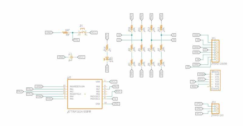
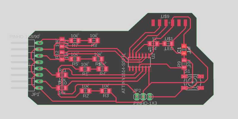
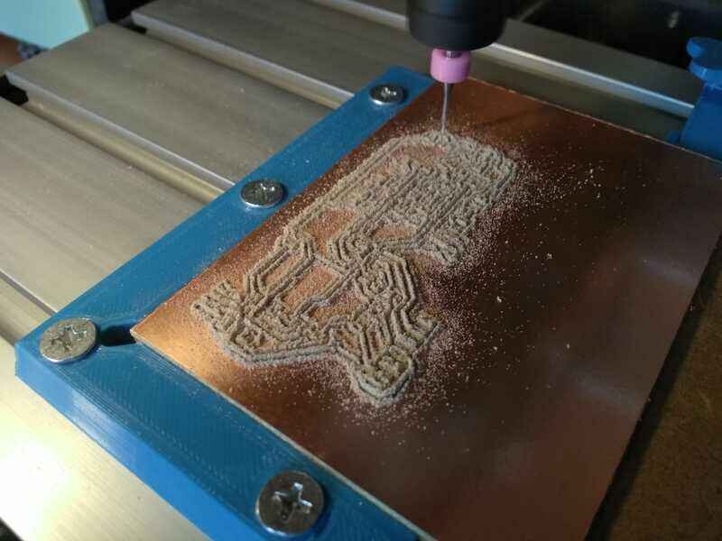
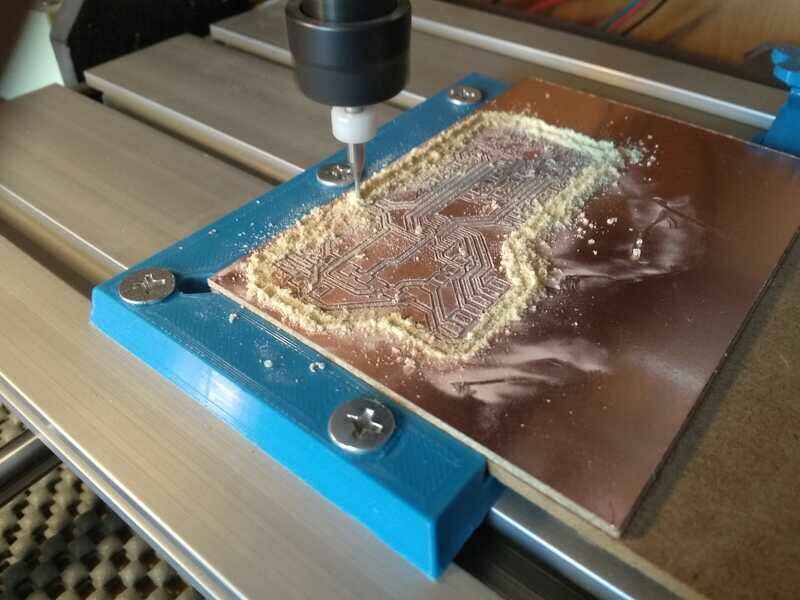
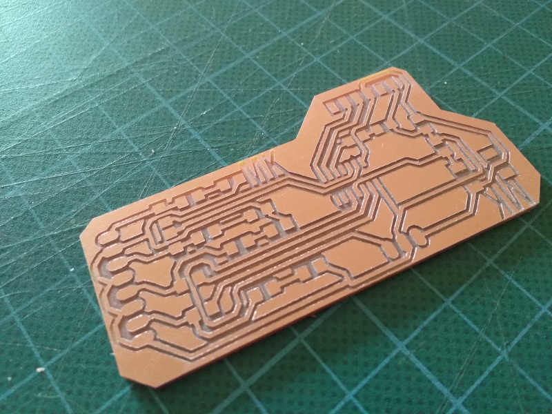
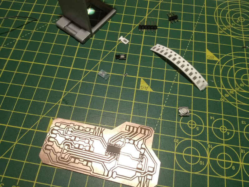
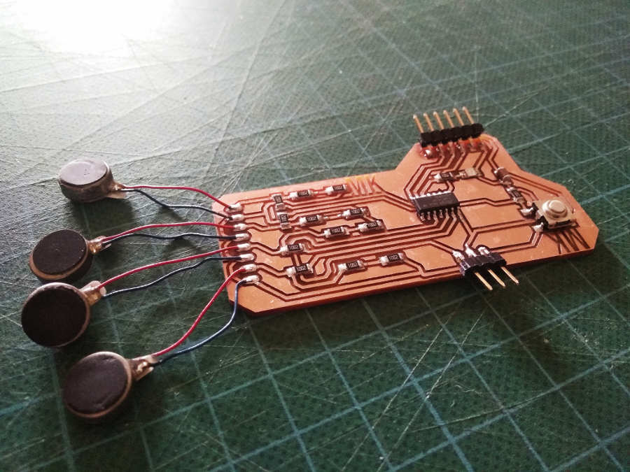
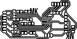
The files (.svg) for the TRACES and the SHAPE

And the 3 pinned UPDI
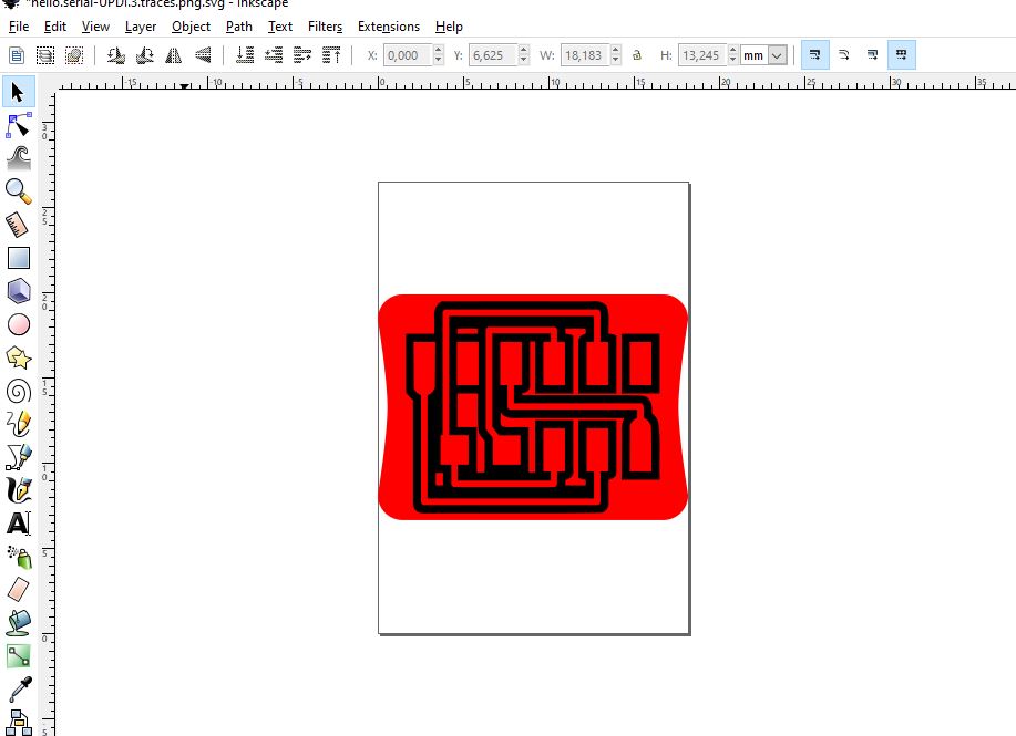

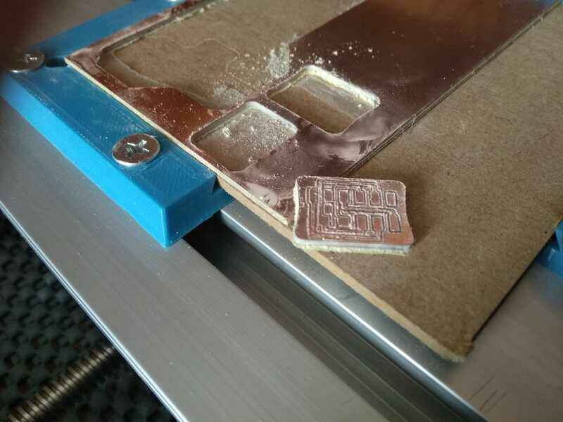
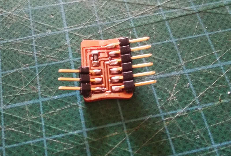
The files (.svg)
I am trying to program in the arduino IDE. to do that I am following Adrian´s tutorial (same as above). I need to add this URL (http://drazzy.com/package_drazzy.com_index.json) by SpenceKonde to the list in the board manager and install the "megaTinyCore by Spence Konde" board library.
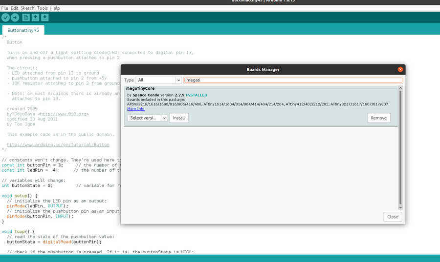
Select: Board attiny1614, chip attiny1614, clock 20MHz, select port and programmer Serial port and 4.7k (pyupdi style).
I am connecting the board with the UPDI 3 pins with jumper cables (making sure to connect to the right pins on the board).
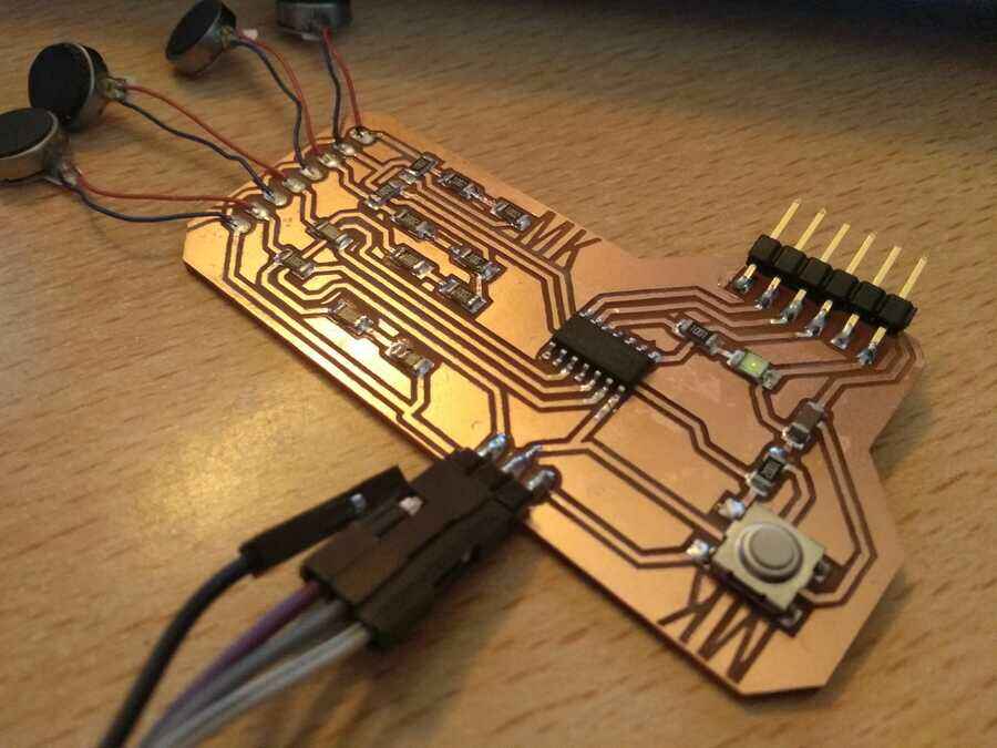
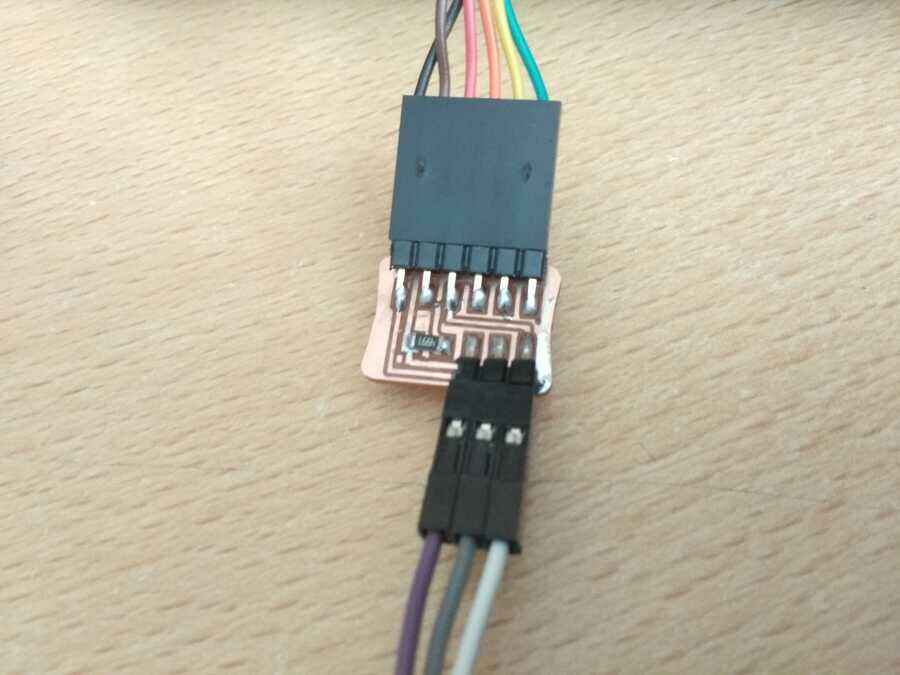
Here is when it gets interesting, my first mistake was to use the physical pin numbers (stated on the datasheet) instead of the names used when using the arduino IDE to program it. In my case I used pin5 instead of pin3 for the LED
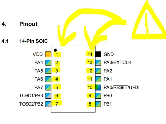
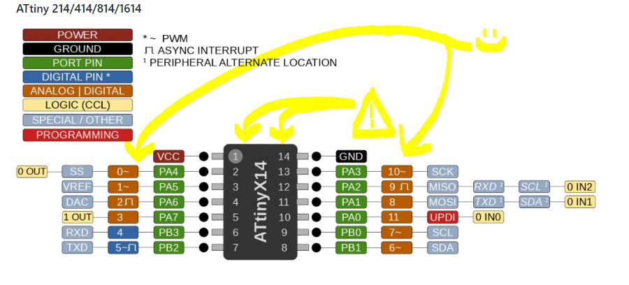
The trouble is that even with that mistake in mind, If I load the program with the wrong pin, the LED still blinks, with very low power voltage (1.8vwhen I measure it with the multimeter), but it blinks...
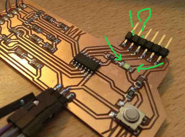
I have check all the continuity and solder points, I also cleaned the board with nail varnish remover (low % of acetone). Now, I can not seem to be able to replicate the last state...and when I program the "blink" example on any of the pins used, the program loads successfully and the LED blinks normally.
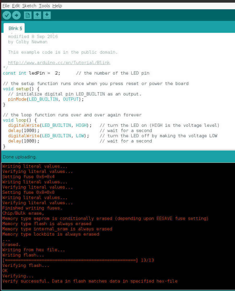
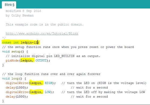
The problem with the "blink" test and the pins used for the LED, comes from the actual program, where I have to asign the pin I want to use as OUTPUT, not only as a "constant", I also need to replace the LED_INBUILT for leppin.
Still no luck with the motors so I am removing them...
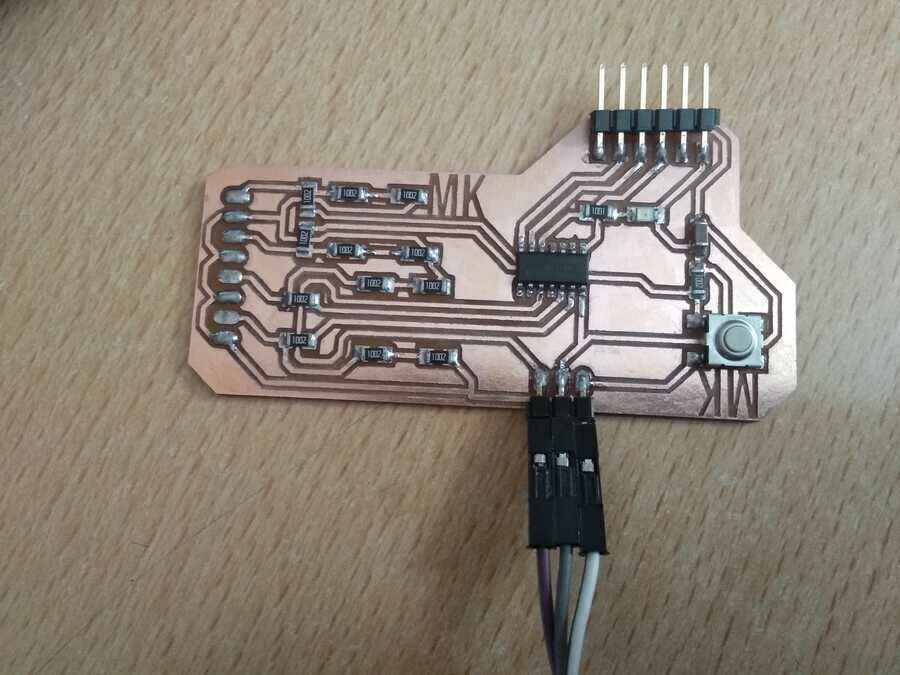
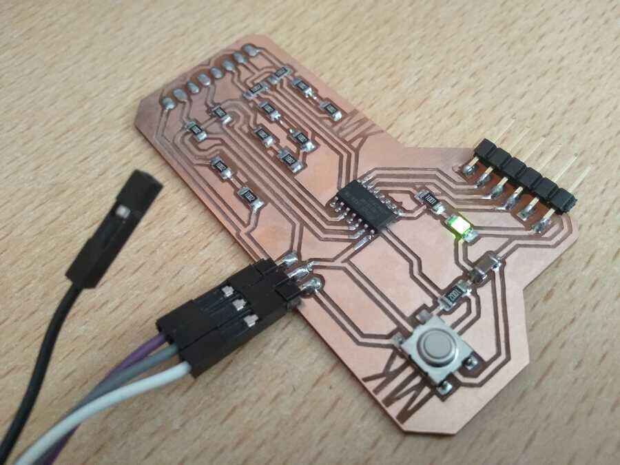
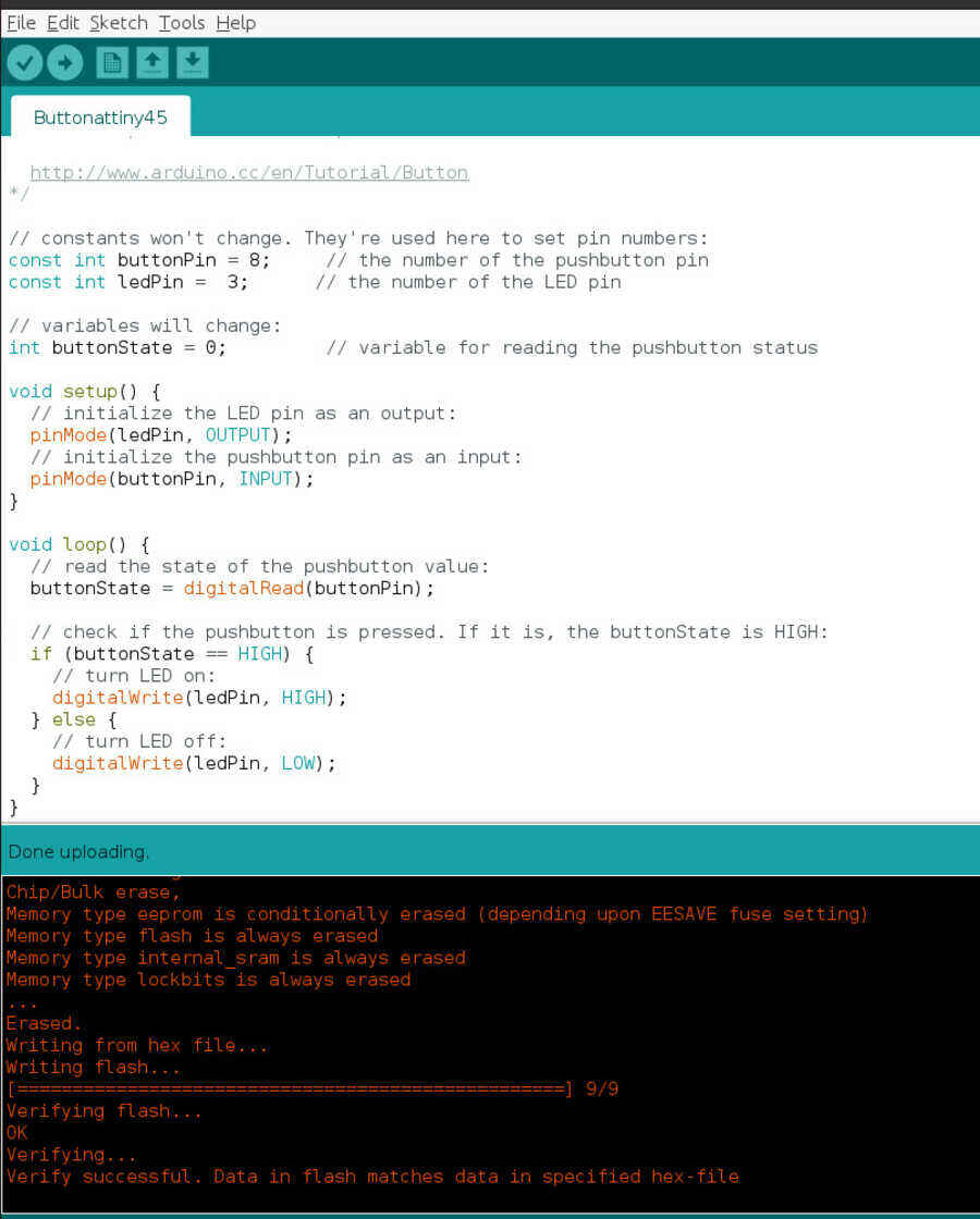
When I load the "button" example, it works perfectly and the LED works with its designated pin...
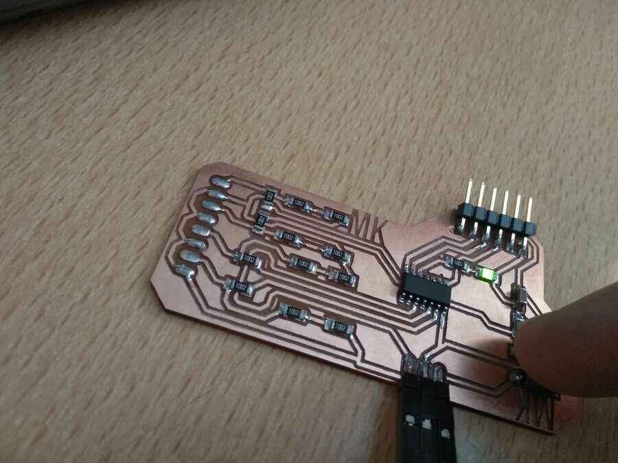
If I assign one of the pins used for the motor instead, I do get 3.3v at the pads with the multimeter (this works for all of them) which is a good sign.
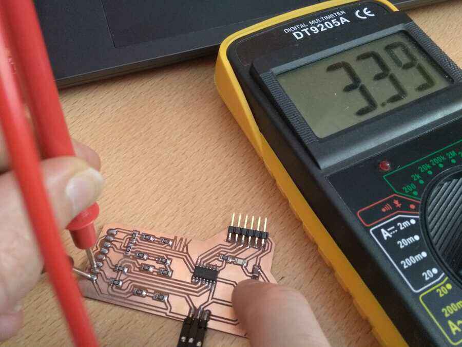
but as soon as I reconnect a motor, the 3.3v disappear, same for all the pins
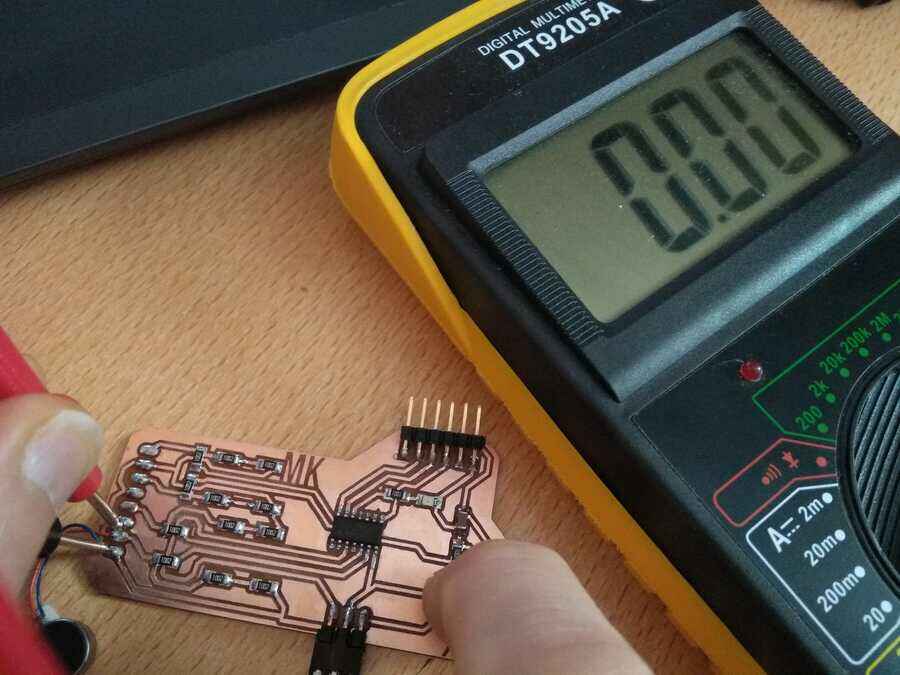
I am testing everything again with the arduino with the blink code, this time without the "voltage divider", I think the motor are my problem because I get the same issue programing the arduino with the "blink" test. When there is no motor, I get 3.3v, if I connect the motor, no 3.3v.
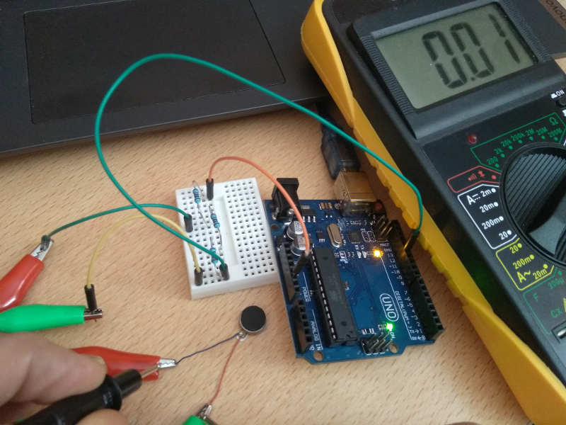
Without the voltage divider
So I need to figure out the current used for theses motors but at first sight, it looks like it should work with 5v....
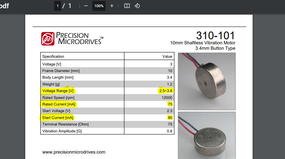
Looking at a different datasheet, I can clearly see that at least 85mA is needed to start the motor and 75mA to run.
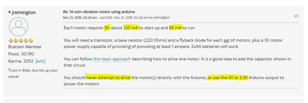
Further more, it looks like it is not a good idea to run the motors either on 5v or from the I/O pins as the motors will draw far too much current...

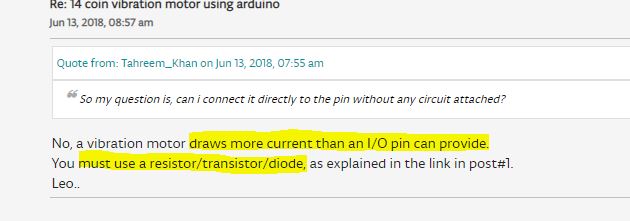
So in my next step, I will design a new board with this configuration in mind: resistor/transitor/diode. More on that in Project development page.
Learning outcomes
Identify relevant information in a microcontroller datasheet.Implement programming protocols.
Have you?
Linked to the group assignment pageDocumented what you learned from reading a microcontroller datasheet.Programmed your boardDescribed the programming process/es you usedIncluded your source codeIncluded a short ‘hero video’ of your board
Key Learnings
- Always use "make flash" followed by "make fuses" — never just one or the other — flashing the firmware and setting the fuses are two separate operations. The board will not behave correctly if you only run one of them.
- The FabISP programmer must be recognised by the host system before programming — run "lsusb" on Linux or check Device Manager on Windows to confirm the programmer appears before attempting to flash a board. If it doesn't appear, check the resistor values on the FabISP first.
- Edit the makefile to match your programmer — the default makefile uses "usbtiny" as the programmer. If you are using an Atmel-ICE or another programmer, change the PROGRAMMER variable in the makefile before running make. Failing to do this gives a cryptic error that doesn't mention the programmer at all.
- CD to the correct directory before running make — make looks for the makefile in the current directory. If you run it from the wrong location it will fail silently or give a confusing error.
- Serial communication speed must match on both ends — if the baud rate in your Arduino/ATtiny code doesn't match the baud rate in your serial monitor or Processing sketch, you will see garbled output. Always set both ends to the same value explicitly.
- ATtiny pin numbers in code are not the same as physical pin numbers — always cross-reference the datasheet pinout diagram. What is labelled Pin 1 on the physical chip is not necessarily digital pin 1 in the code.
- Use a logic analyser or oscilloscope to debug serial communication — if your serial output looks wrong, a logic analyser will show you exactly what bits are being sent. This saved hours of debugging during the networking week.
Related weeks
Week 4 - Electronic production —
The FabISP in-circuit programmer made in Week 4 was used to flash all ATtiny boards programmed this week.
Week 6 - Electronic design —
Boards designed in Week 6 were programmed using the makefile workflow developed here.
Week 10 - Input device —
Capacitive touch sensing for the brain model built directly on the ATtiny programming skills from this week.
Week 12 - Output device —
The ATtiny1614 driver board for vibration motors and LEDs was programmed using this week's workflow.
Week 13 - Networking and communications —
UART networking between ATtiny nodes built on the serial communication foundations established here.
Final Project —
Embedded programming of all microcontrollers in the final brain model system.