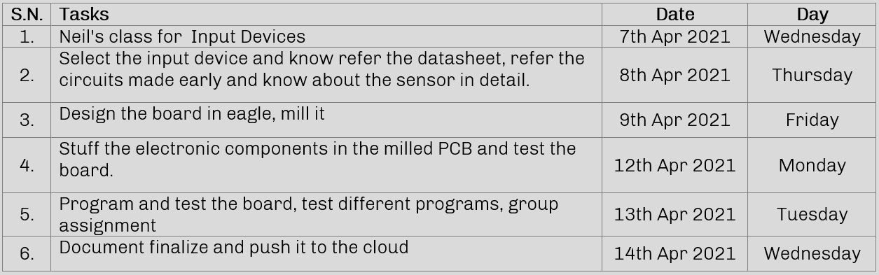
Group
1. Probe an input device's analog levels and digital signals
Individual
1. Measure something: add a sensor to a microcontroller board that you have designed and read it
Plan for the week
An input device is any hardware device that sends data to another device, allowing you to visualized, monitor, interact or can be used to process and actuate output device. A basic example of an input device that we use in our daily life is keyboard, mouse, camera, joystick etc.
Talking about our daily life, there are many other input devices that are in the machines that we use for our living like AC, refrigerator, TV, washing machine, mobile phone etc. They all use sensors to function. Sensors take some input and convert it to the electrical signal which it sends the main board which then analyze it to perform different tasks via actuators or other output devices
Sensor
Sensor is an input device which provides an output (signal) with respect to a specific physical quantity (input). It is the device which provides input to a main control system (like a Processor or a Microcontroller). It can also defined as a device that converts signals from one energy domain to electrical domain.
The simplest example of a sensor is an LDR or a Light Dependent Resistor. It is a device, whose resistance varies according to intensity of light it is subjected to. When the light falling on an LDR is more, its resistance becomes very less and when the light is less, well, the resistance of the LDR becomes very high.
We can connect this LDR in a voltage divider (along with other resistor) and check the voltage drop across the LDR. This voltage can be calibrated to the amount of light falling on the LDR, hence, a Light Sensor.
Hall Sensor
Hall-effect sensors are the linear transducers (A transducer is an electrical device that is used to convert one form of energy into another form ) that are used to measure the magnitude of the magnetic field. Working on the principle of Hall Effect, these sensors generate a Hall voltage when a magnetic field is detected, which is used to measure the magnetic flux density.
Linear sensors can measure the wide range of magnetic fields. Besides magnetic fields, these sensors are also used for detecting proximity, position, speed. For these sensors output voltage is directly proportional to the magnitude of the magnetic field.
The principle of Hall voltage is used as a working principle of the Hall Effect sensor. On a thin strip of a conductor, electrons flow in a straight line when electricity is applied. When this charged conductor comes in contact with the magnetic field which is in a perpendicular direction to the motion of electrons, the electrons get deflected.
Some electrons get collected on one side while some on another side. Due to this, one of the conductor’s plane behaves as negatively charged while the other behaves as positively charged. This creates potential difference and voltage is generated. This voltage is called the Hall voltage.
The electrons continue to move from one side of the plane to other till a balance is achieved between the force applied on charged particles due to an electric field and the force that caused magnetic flux that caused this change. When this separation stops, the hall voltage value at that instant gives the measure of magnetic flux density.
Based on the relation between hall voltage and magnetic flux density, Hall Effect sensors are of two types. In the linear sensor, the output voltage is linearly related to magnetic flux density. In the threshold sensor, at each magnetic flux density, the output voltage will have a sharp decrease.
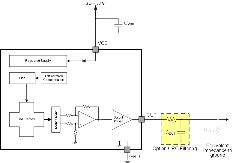
Hall Effect sensors can be viewed as linear transducers. To process the sensor’s output these require a linear circuit that can provide a constant driving current to the sensors and also amplifies the output signal.
Some of the examples for the application of Hall Effect sensors are the current transformers, Position sensing, Galaxy S4 Accessories, Keyboard switch, computers, Proximity sensing, speed detection, current sensing applications, tachometers, anti-lock braking systems, magnetometers, DC motors, disk drives etc…
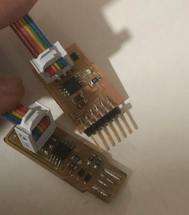
PCB Design
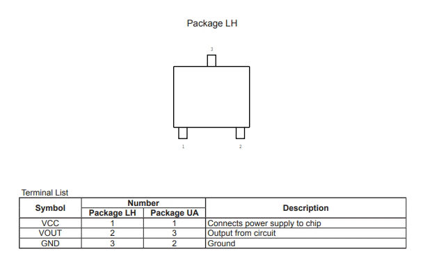
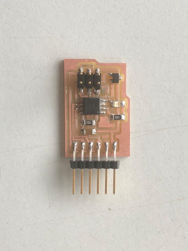
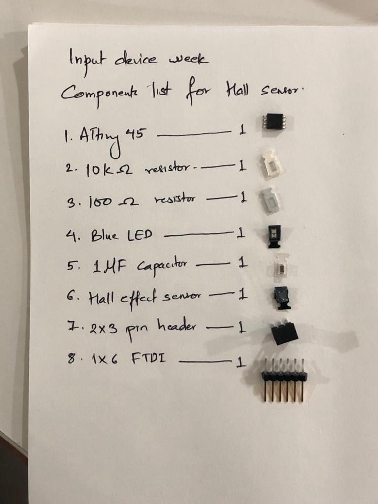
For PCB design as previous week, I used Eagle. Details about how to design the board in Design week. Here I designed the board such that one LED can be connected to to one port so that I can program it according to the input from the hall sensor. First I referred the datasheet of the hall sensor that we are using which can download from this link.
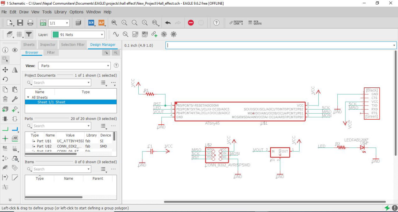
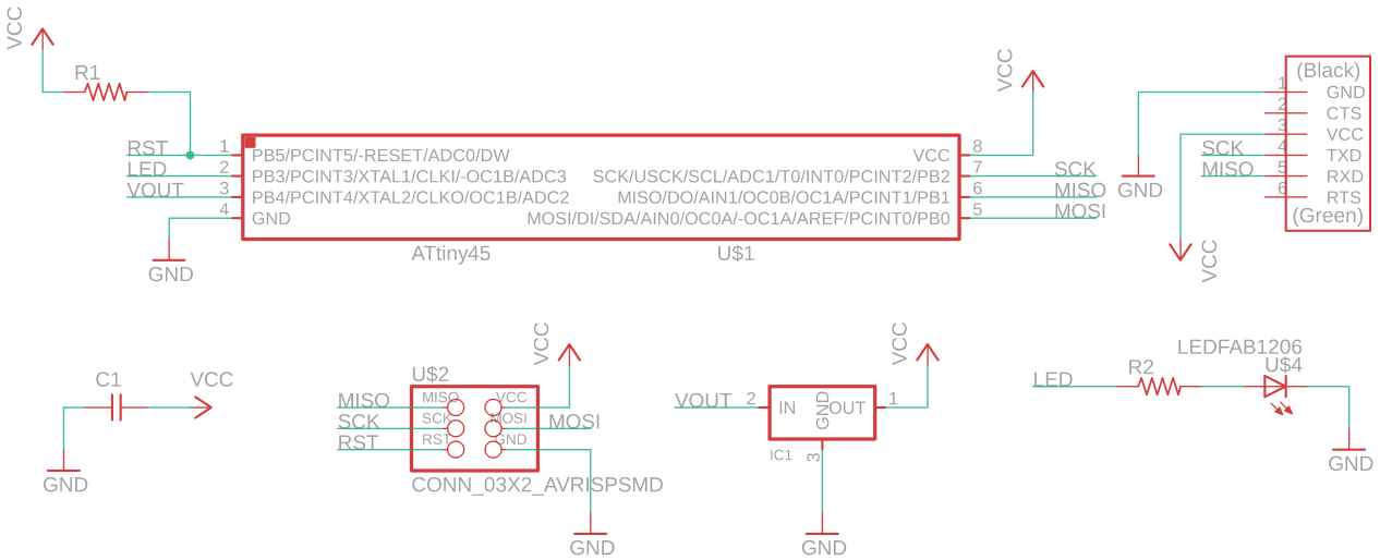
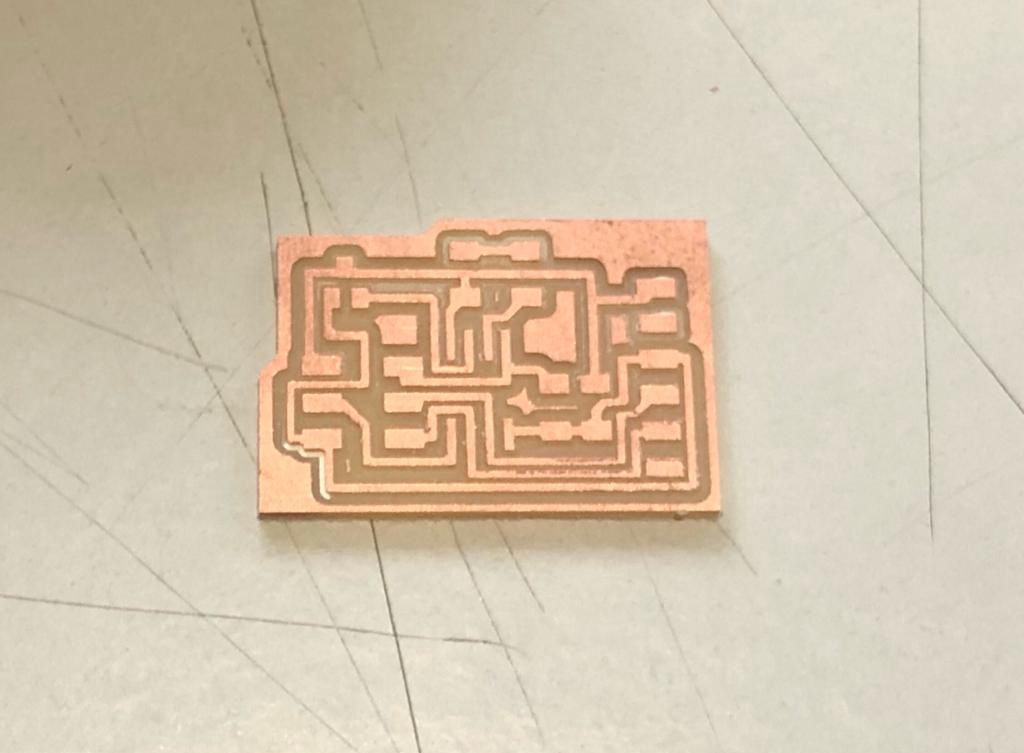
Then I switched to board design followed by setting design rules and then routing the wires, some by auto and some manually finally getting following board
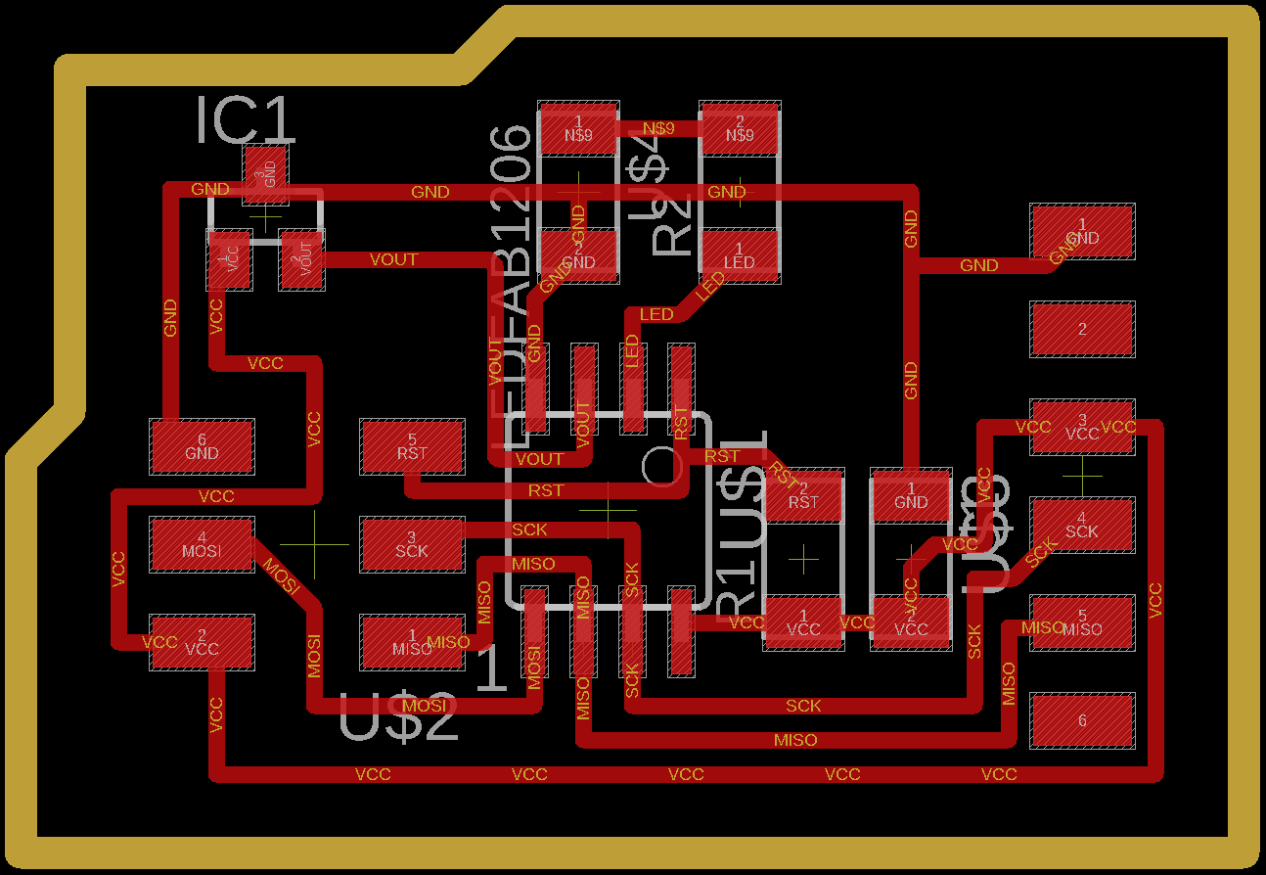
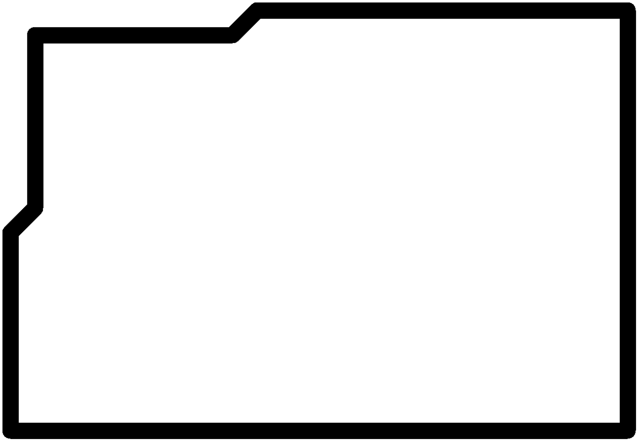
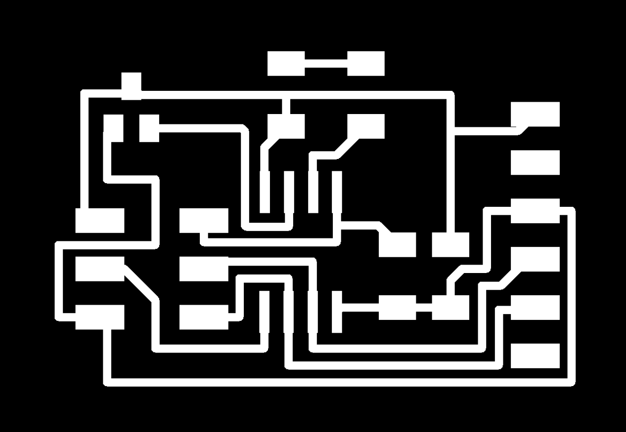
Then the trace image and trim image was exported as follows and then milling was done. You can download trace and trim here.
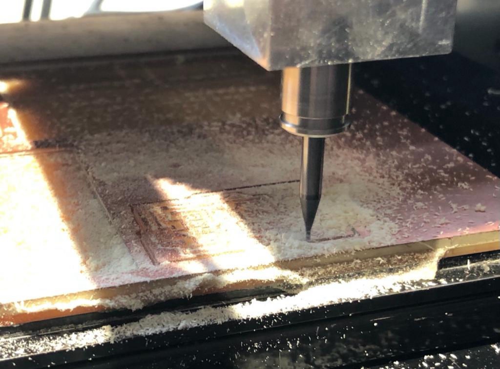
Stuffing the electronic components into the milled PCB
Now after burning the bootloader, coding is done where
#include <SoftwareSerial.h>
int sensorPin = 4;// hall effect sensor (you should change the pin number from 4 to the pin you have connected your sensor to)
int digitalValue = 0;// variable to store the value coming from sensor
int analogValue = 0;
SoftwareSerial Serial(1, 2); //(Tx, Rx pins for serial response)
void setup()
{
pinMode(sensorPin, INPUT_PULLUP);
pinMode(3, OUTPUT);
Serial.begin(9600); // initialize serial communications at 9600 bps
}
void loop()
{
analogValue = analogRead(A2); //reads the analog value
digitalValue = digitalRead(sensorPin);
//reads the value from pin
Serial.print("Analog Value ");
Serial.print(analogValue);
Serial.print(" Digital Value ");
Serial.println(digitalValue);
delay(100);
}
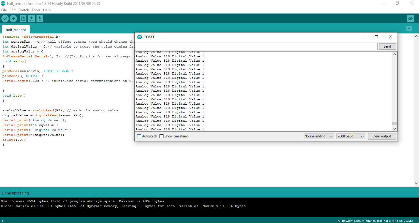
The serial response from the sensor
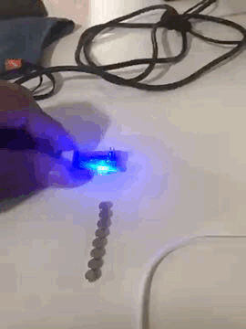
Now that we can see the sensor is working, Now it is programmed to turn on and off the light according to the polarity
void setup()
{
pinMode(4, INPUT_PULLUP);
pinMode(3, OUTPUT);
}
void loop()
{
int data = digitalRead(4);
if (data == 1 ) {
digitalWrite(3, LOW);
}
else {
digitalWrite(3, HIGH);
}
}
Group Assignment
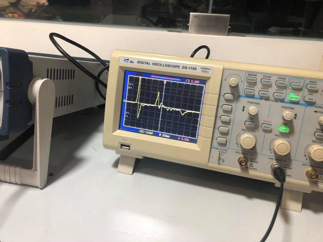
As a group assignment, we probed hall sensor where the character of the hall sensor was visualized in the digital oscilloscope.
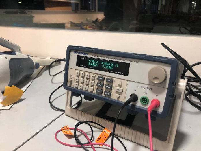
First the 5V is given from the Programmable DC Power Supply to the hall sensor and then, first set the oscilloscope to DC supply. Then autoset the oscilloscope. After there is a green liight in the Run/Stop, place the black wire to the ground and the vcc to the vout of the hall sensor.
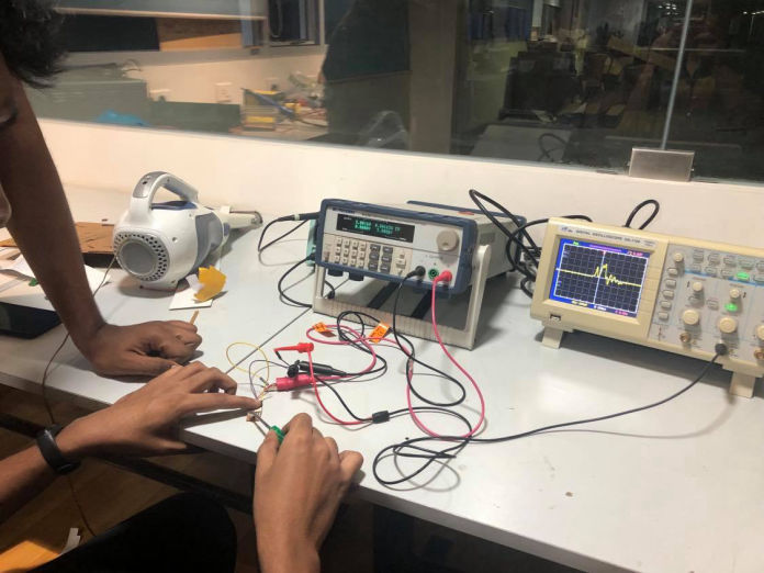
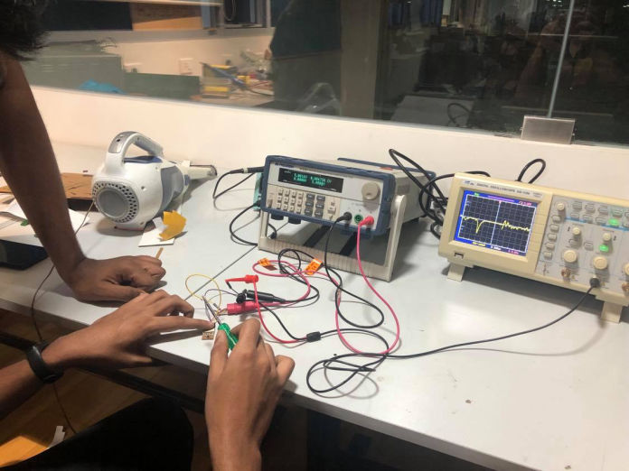
Now after the circuits are completed, get one magnet and take it near to the hall sensor. Here you will notice that when you move your magnet closer there is oscillation and when it is released suddenly, there is a immediate oscillation in opposite direction. It behave reacrive when the magnet was raised very quickly.
Similarly, when you bring one surface of a magnet closer it oscillates and if the magnet is flipped the signal is also in opposite direction meaning, two poles in magnets wil
This site was created with Mobirise themes