Group
1. Use the test equipment in your lab to observe the operation of a microcontroller circuit board
Individual
1. Redraw an echo hello-world board
2. Add (at least) a button and LED (with current-limiting resistor)
3. Check the design rules, make it, and test it
4. Extra credit: simulate its operation
Plan for the week
This week we will be focusing on the Electronics Design. We will design a PCB through a designing software, fabricate it and test it. There are many softwares where a PCB can be designed like KICAD, Autodesk Eagle, circuitmaker etc but we will be using Autodesk Eagle for ease. I, personally had no idea about electronics as well as designing. I came to know about electronics production in week 4 and now designing is a new challenge for me. I am excited as well as nervous for this week.
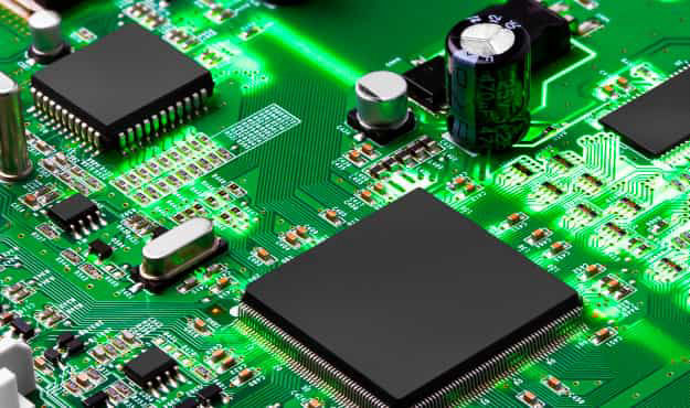
A printed circuit board (PCB) consists of a board which is milled or etched from a copper laminated board on one/both side of a subtrate layer like epoxy, fiberglass, ceramic etc in such a way to connect different terminals of the electronics component that are soldered on to it. you can know more about PCB in this link.
Designing PCB
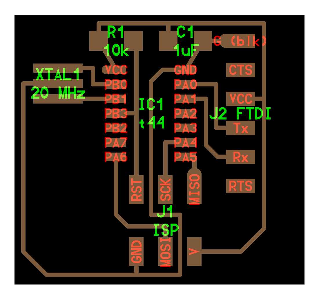
There are many tools in which you can design a PCB like Autodesk Eagle, KiCAD, LibrePCB, etc. We will be using Eagle for designing out PCB. For this we will be redesigning a Echo Hello World Board. First the board is studied like routes, electronic components, etc to reverse engineer it on the Eagle so that we can learn about designing PCB from the process.
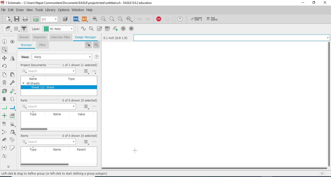
Exploring Eagle
EAGLE is electronic design automation (EDA) software that lets printed circuit board (PCB) designers seamlessly connect schematic diagrams, component placement, PCB routing, and comprehensive library content. Please refer this link if you want to know in detail about PCB design in eagle
Initial process
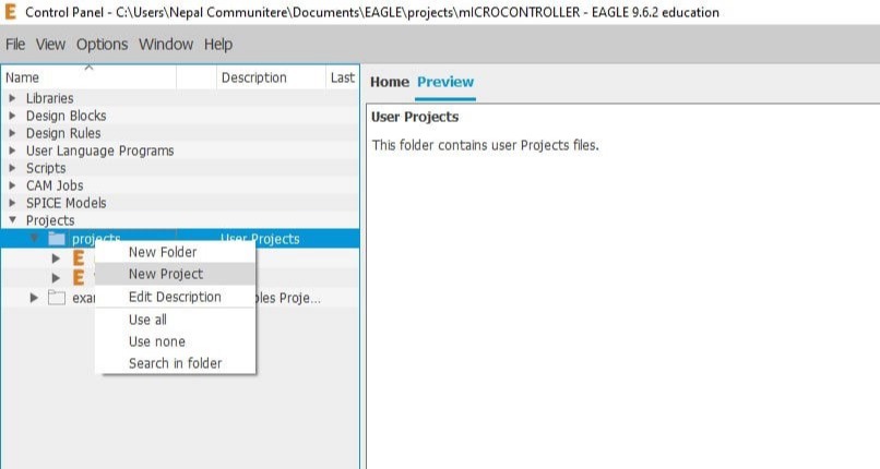
You can move parts by clicking on move and then a "+" sign between the shapes.
Now we have to add Led and a switch to the current board where possible. I decided to put 3 LED in the PCB. For LED, you have to balance the voltage in the LED, hence a resistor had been added. The way to calculate resistance value is:
If,
Main supply volatage = V,
Rated voltage for LED = V1,
Rated current for LED = I1
Then,
Value of resistor in series= (V-V1)/I1
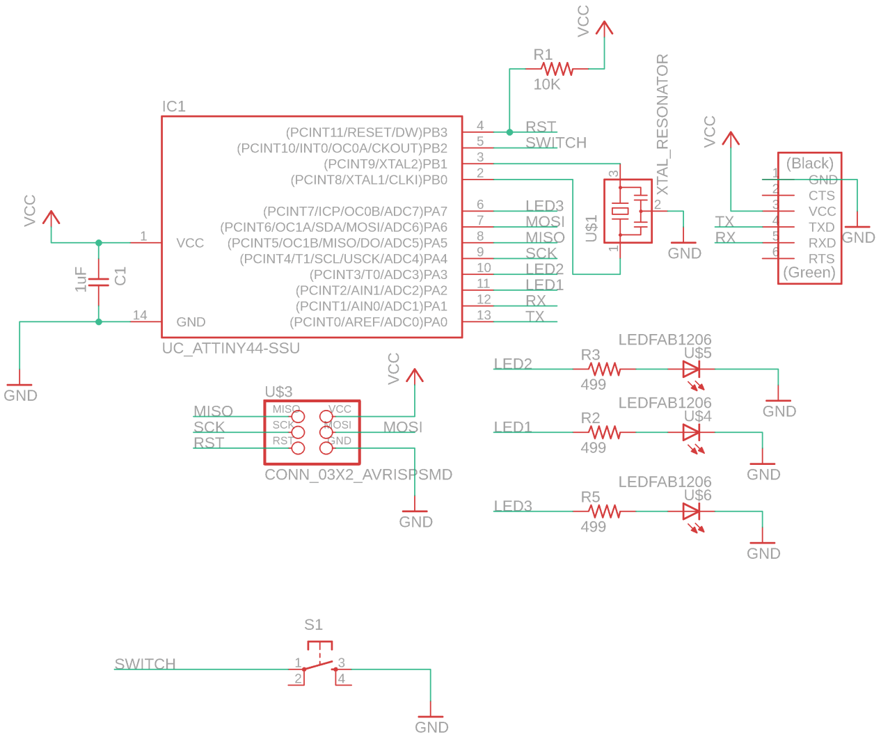
Then the three LED of Red, Green and Blue is added as FabLab logo in the ports PA7(6), PA3(10) and PA2(11) and a tactile switch is added on PB2(5) port and finally the schematic is finished. (The pins are recognized according to datasheet of the ATtiny 44 which you can know about in embedded programming week)
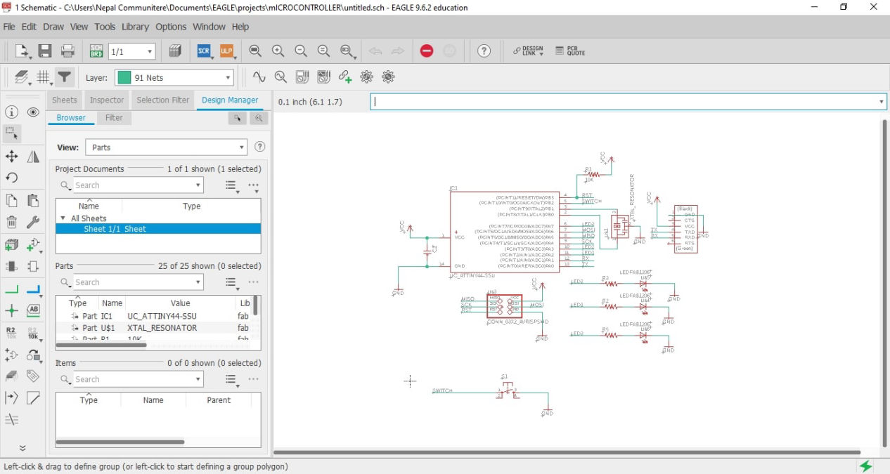
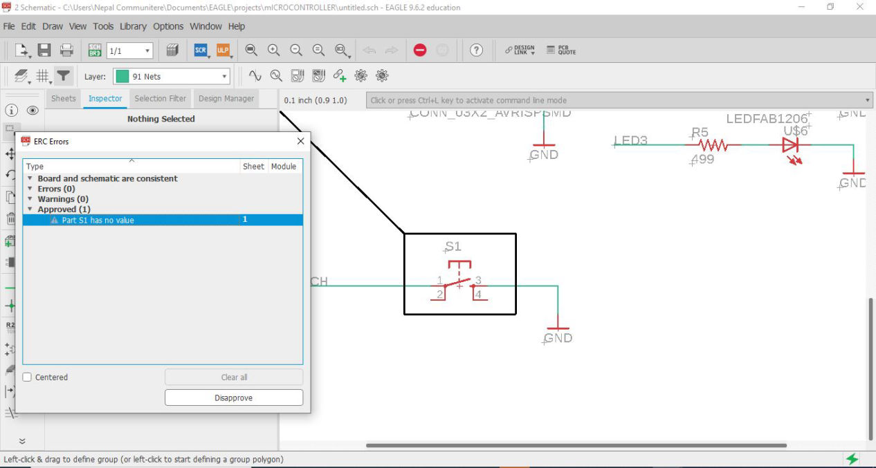
Then I did ERC where, it showed that the I had not inserted the values of the resistors and capacitors, then I added the values. the again did ERC where everything was ok.
Download the schematics here
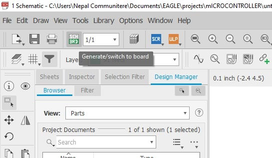
After the schematics is finished, click on the switch to board inside file menu or click on the "SCH-BRD" on the top left corner.
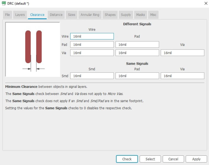
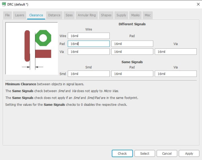
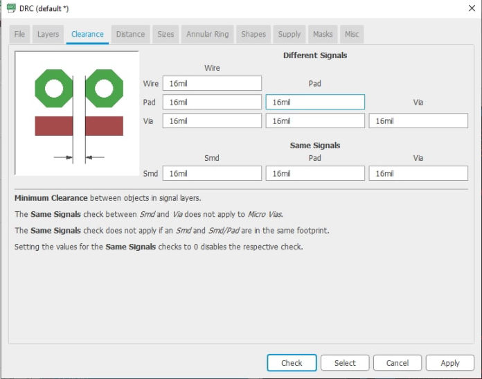
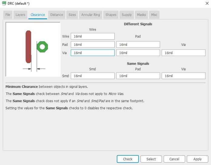
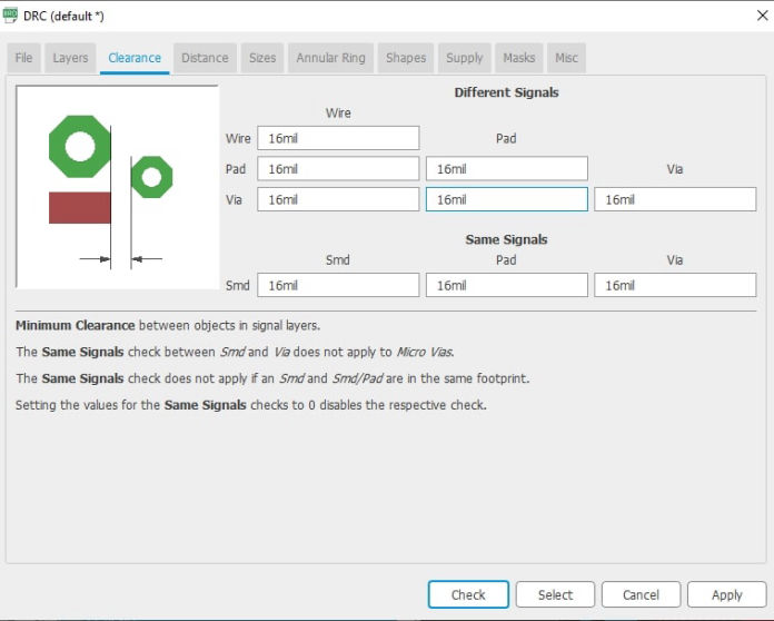
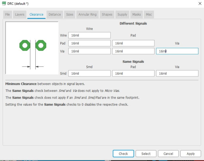
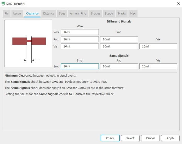
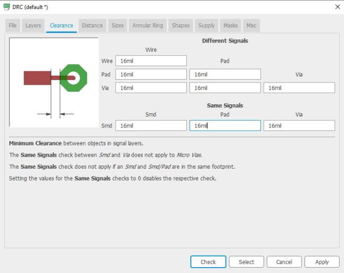
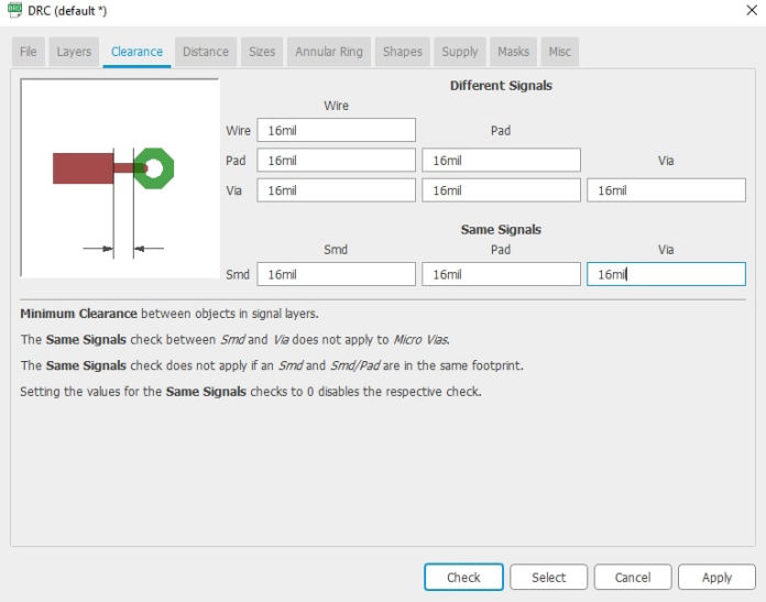
Now that you are on the board, first thing to do is connect set the design rules which you can get into by clicking DRC inside tools menu. As we are using 16 mill bit, setting clearances of 16mill bit was the first thing to do. Set 16 mill to different clearances between wire, pad, via and smt.
After setting the design rules, the components are moved into the board and arranged so that there is minimum crossings between wires. Then press auto router. This will try to simulate the wirings keeping components at a fixed place. Now what you can do is connect the components manually where possible and using both auto router and manual input, wiring is done. Then click on move and dragging the boudray line in yellow and shrink it which just fits the design and if you want add cut line in the bottom layer to trim the board.
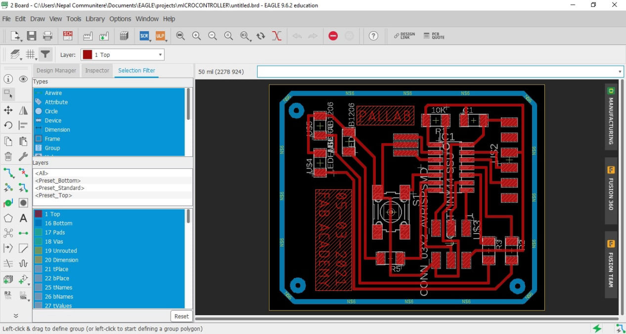
Then the again it was checked from the DRC to see if there is any issue with the trim and clearances.There would be warnings in the screen when there is any problem according to the design rules. If there is any fix them and you should be able to export the files for milling.
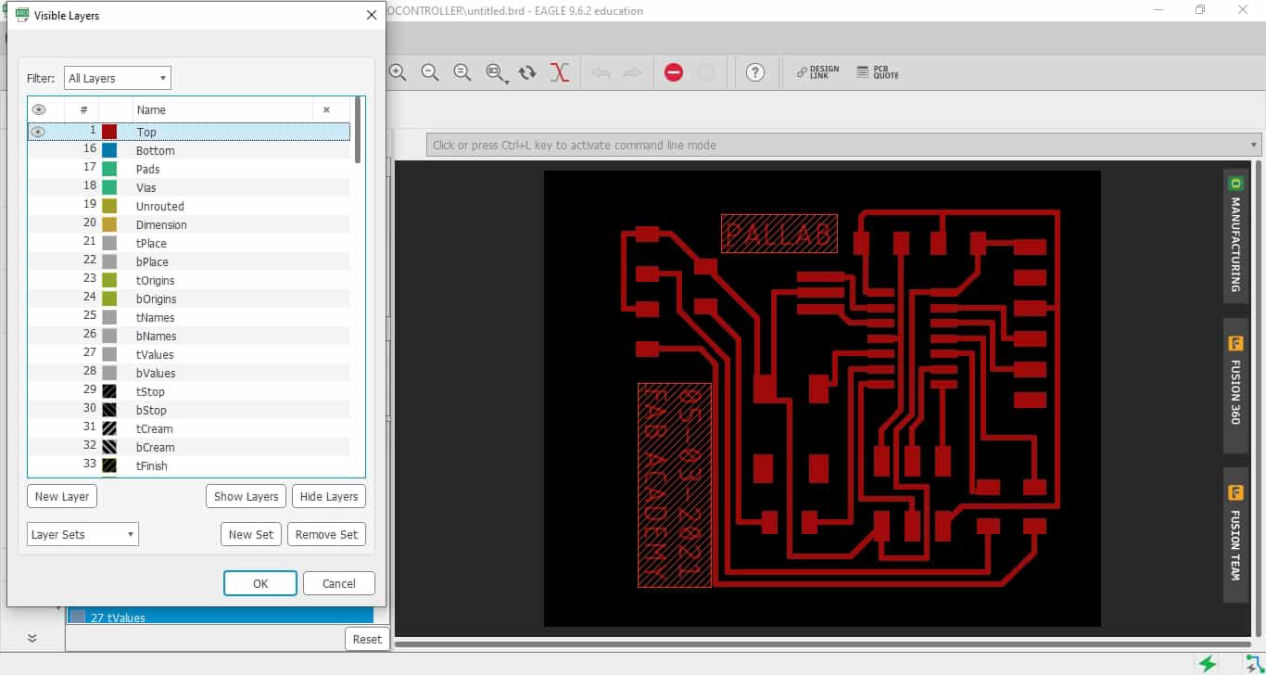
For exporting the image you have to show only the layers which you want to trace and trim. For this there is a tool on the top left corner, hide all layers and show the top which will be used for tracing using 1/64 inch mill
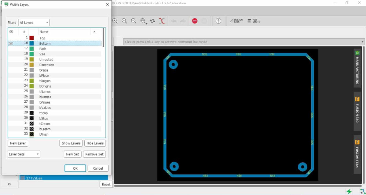
Do the same for the trim line as well
To get the png file, first select the top layer for trace, show top layer, export as image, browse the folder where you want to export, check on monochrome, select dpi, 2000 (you can change it according to you requirement) and save.
You should be able to get following files.
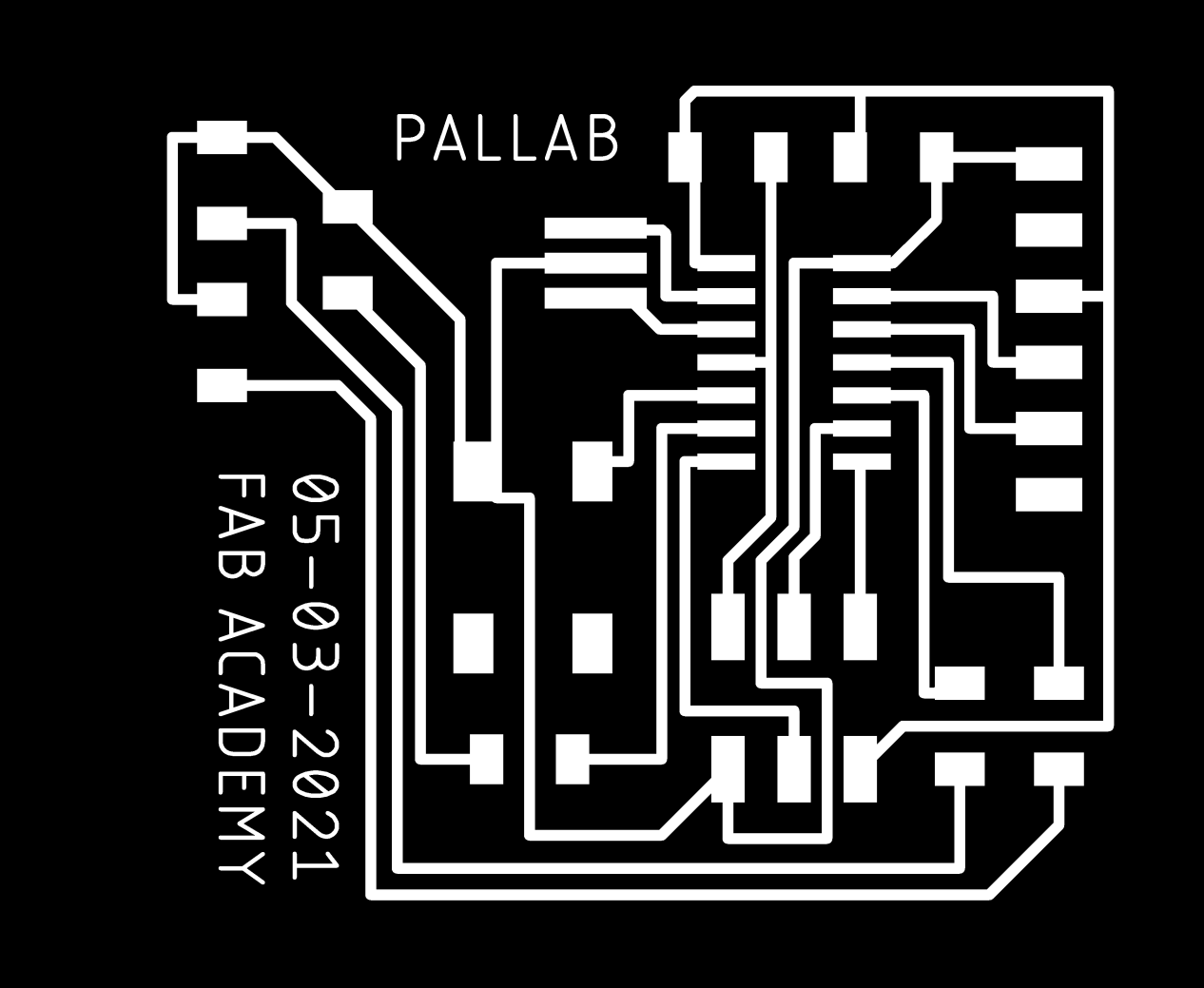
Download traces and trim line here
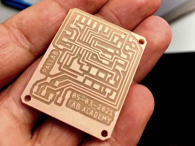
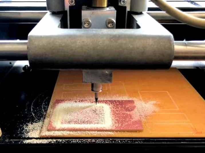
Now after getting the image use it to mill the PCB from MDX-20. You can know the process of milling here.
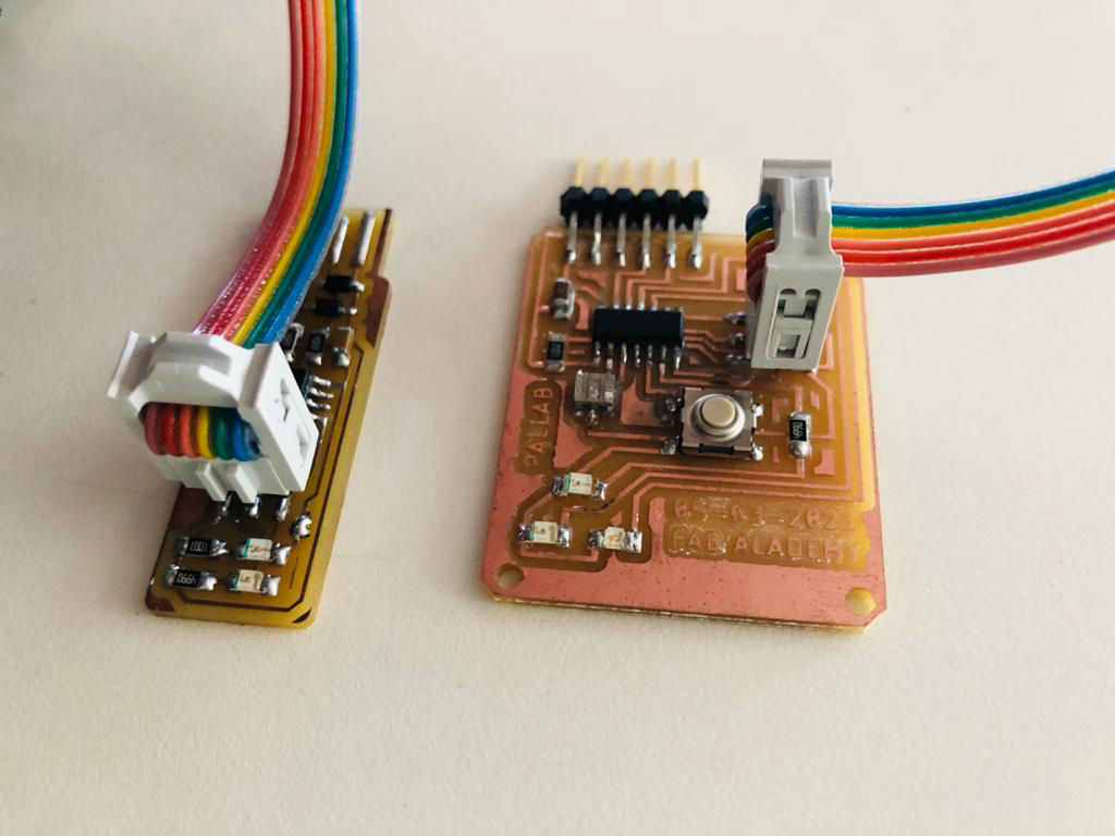
After collecting the electronic components, it is stuffed on the board by soldering according to the board design.
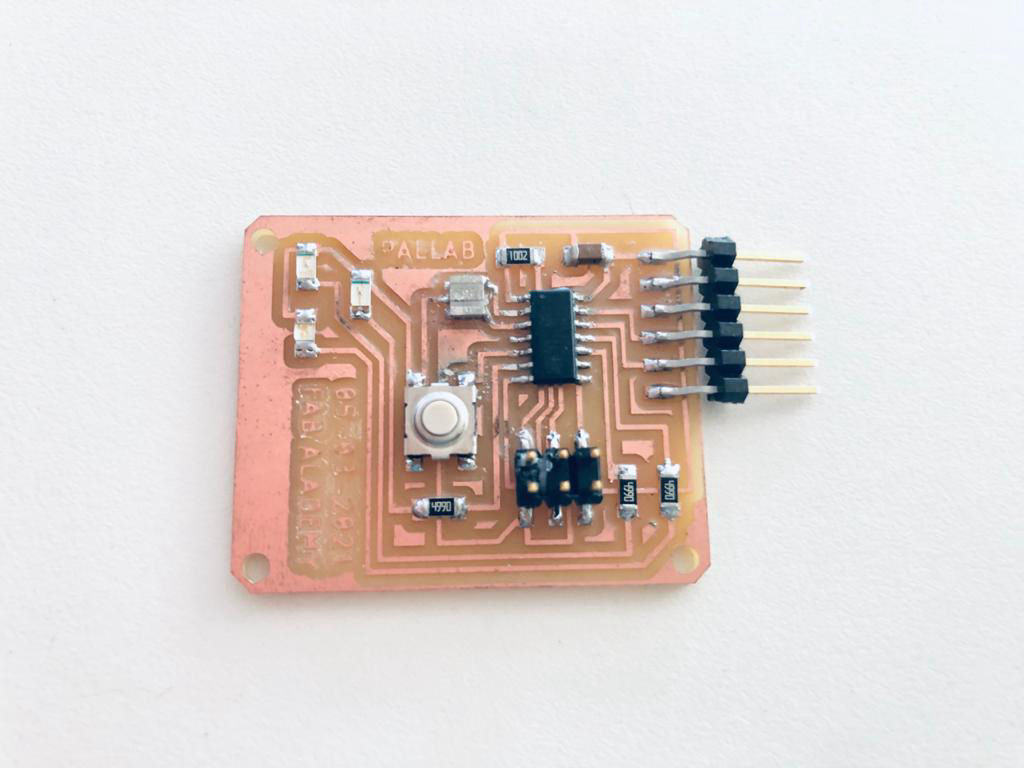
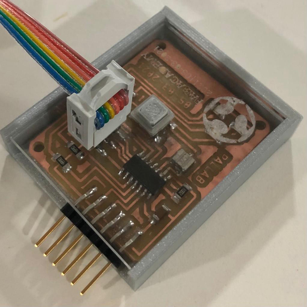
After soldering, the connection is inspected again using the multi-meter and then connected to the ISP using a jumper cable for testing the board.
Now after it is connected upload the the program to the board using Arduino IDE. For getting the board setting in IDE,
1. Goto
File >> Preferences
2. Copy the link
https://raw.githubusercontent.com/damellis/attiny/ide-1.6.x-boards-manager/package_damellis_attiny_index.json
in Additional Board Manager URLs.
3. Goto Board Manager, Search for ATtiny44 and install it.
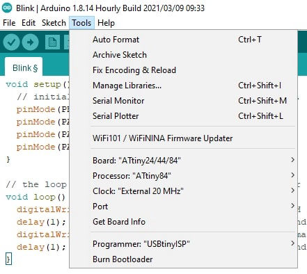
4. Goto
Menu >> Tools
Select
Board >> ATtiny 22/44/84
Processor >> ATtiny 84
Clock >> External 20 MHz
Now the program was compile pushed and tested in the board.
// constants won't change. They're used here to set pin numbers:
const int buttonPin = 8; // the number of the pushbutton pin
const int ledPin1 = 3;
const int ledPin2 = 2;
const int ledPin3 = 7;
// variables will change:
int buttonState = 1; // variable for reading the pushbutton status
void setup() {
// initialize the LED pin as an output:
pinMode(ledPin1, OUTPUT);
pinMode(ledPin2, OUTPUT);
pinMode(ledPin3, OUTPUT);
// initialize the pushbutton pin as an input:
pinMode(buttonPin, INPUT_PULLUP);
}
void loop() {
// read the state of the pushbutton value:
buttonState = digitalRead(buttonPin);
// check if the pushbutton is pressed. If it is, the buttonState is HIGH:
if (buttonState == HIGH) {
// turn LED off:
digitalWrite(ledPin1, LOW);
digitalWrite(ledPin2, LOW);
digitalWrite(ledPin3, LOW);
} else {
// turn LED on:
digitalWrite(ledPin1, HIGH);
delay (2);
digitalWrite(ledPin1, LOW);
delay (2);
digitalWrite(ledPin3, HIGH);
delay (2);
digitalWrite(ledPin3, LOW);
delay (2);
digitalWrite(ledPin2, HIGH);
delay (2);
digitalWrite(ledPin2, LOW);
delay (2);
}
}
Here internal pull up resistors required as my switch works on open-drain system. Which means, that the pin is always high and when switch is connected there is an open drain which signifies that the switch is on. If you do the design wherethe switch is open, the state of your input is "floating". If you try to digitalRead or analogRead that input, the value will be pretty much just noise. so to avoid this, pull up resistors are used.
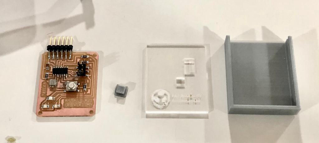
The casing was designed and fabricated using laser cutter and 3D printer. The parts fabricated are as shown in the picture.
Tadaaaa.....
Group assignment
This week's group assignment is use the test equipment in the lab to observe the operation of a microcontroller circuit board
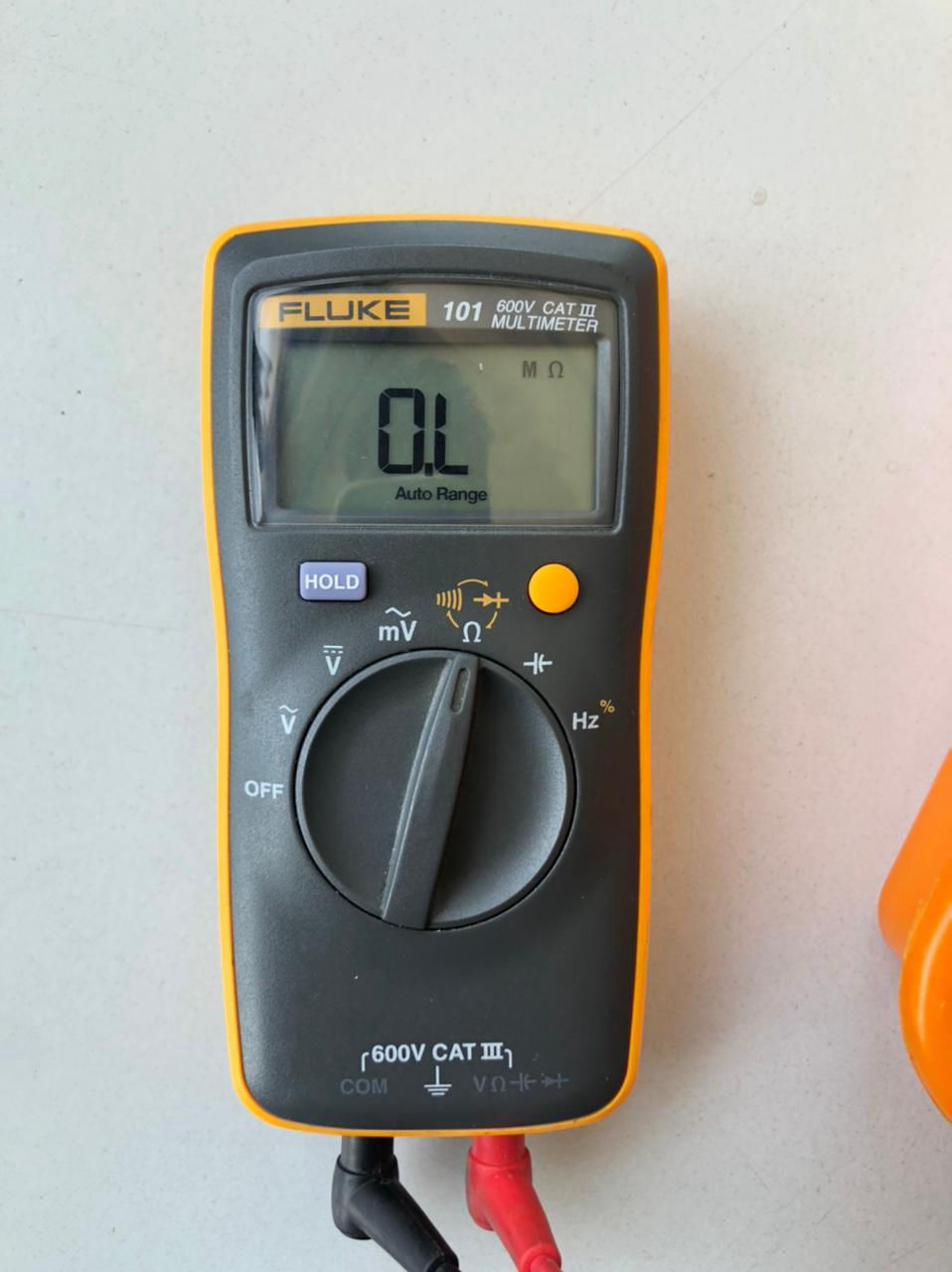
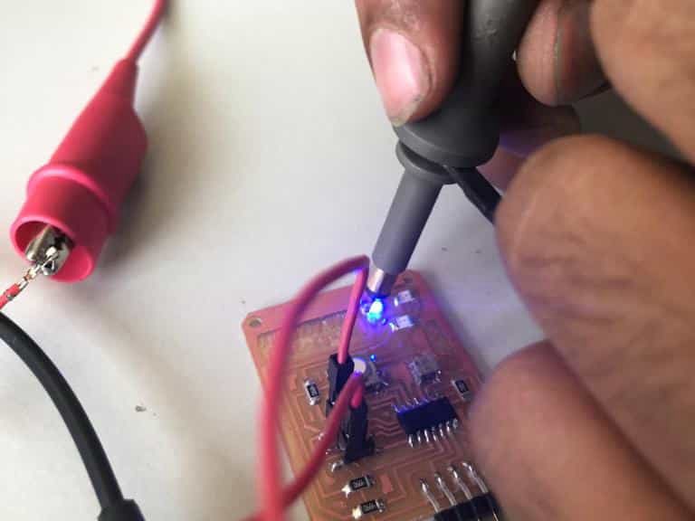
This equipment is used mostly to measure continuity and isolation of the traces. It was also used to find the polarity as well for diodes.
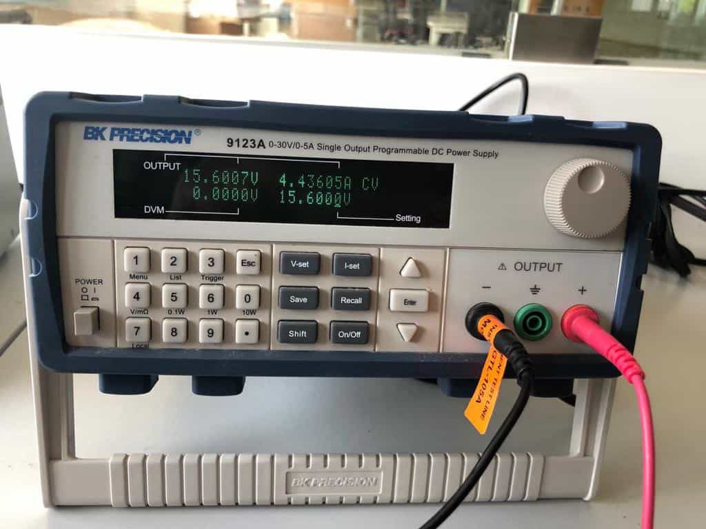
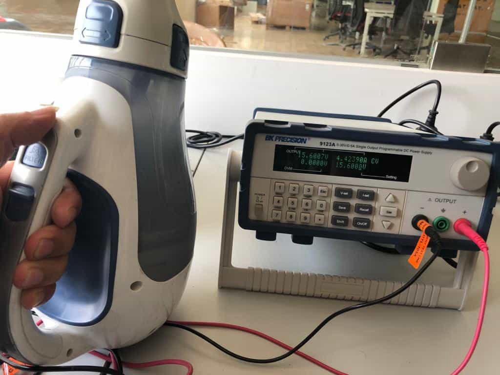
This has been used to calculate the current in the controller board. In parallel is was used to calculate the power in the vacuum cleaner that we had in lab as well. Power of the vacuum cleaner was calculated to be 69W from the power supply by setting rated voltage of 15.6V
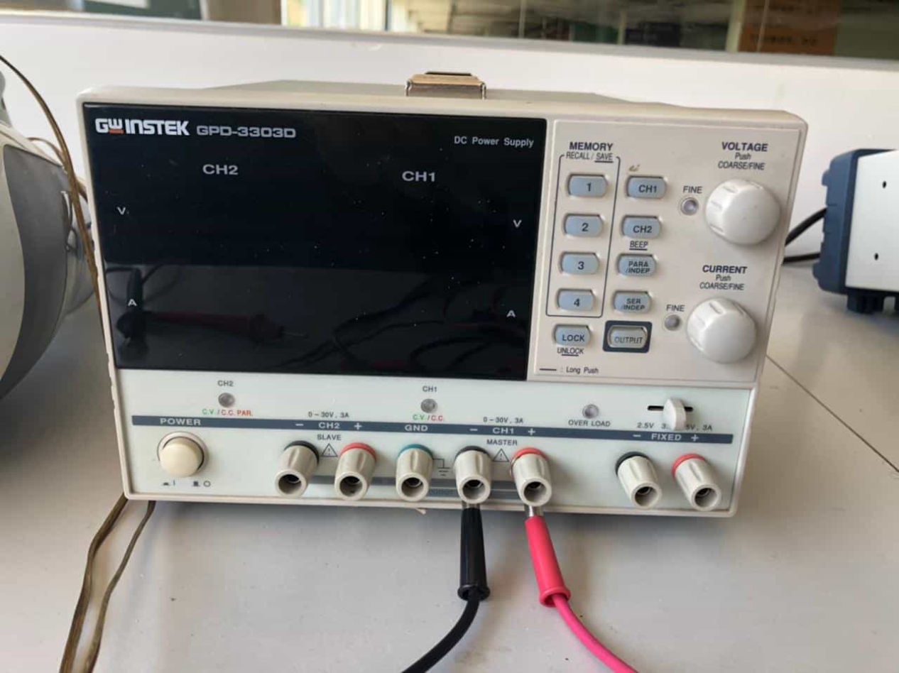
INSTEK GPD-3303D Power Supply
Instek GPD-3303D is a Multiple Output Programmable Linear D.C. Power Supply. The GPD-X303 Series offers digital panel control, large display, bright LED indicators, high output resolution, 4 sets of setup memory, USB remote control and smart cooling fan control. Additionally , the GPD-X303S Series provides easy operation , a wide selection of panel setting and operation.
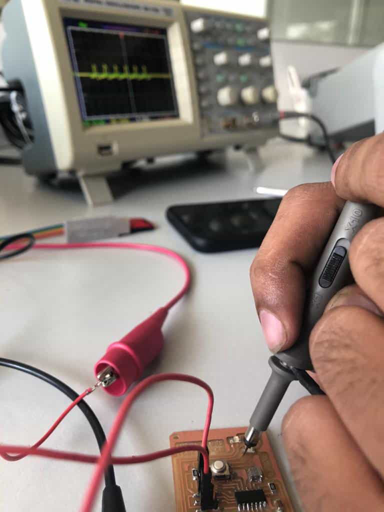
UNISOURCE DS-1100 100 MHZ, 2 CH, Digital Storage Oscilloscope
The digital storage oscilloscope is an instrument which gives the storage of a digital waveform or the digital copy of the waveform. It allows us to store the signal or the waveform in the digital format, and in the digital memory also it allows us to do the digital signal processing techniques over that signal. The maximum frequency measured on the digital signal oscilloscope depends upon two things they are: sampling rate of the scope and the nature of the converter. The traces in DSO are bright, highly defined, and displayed within seconds.
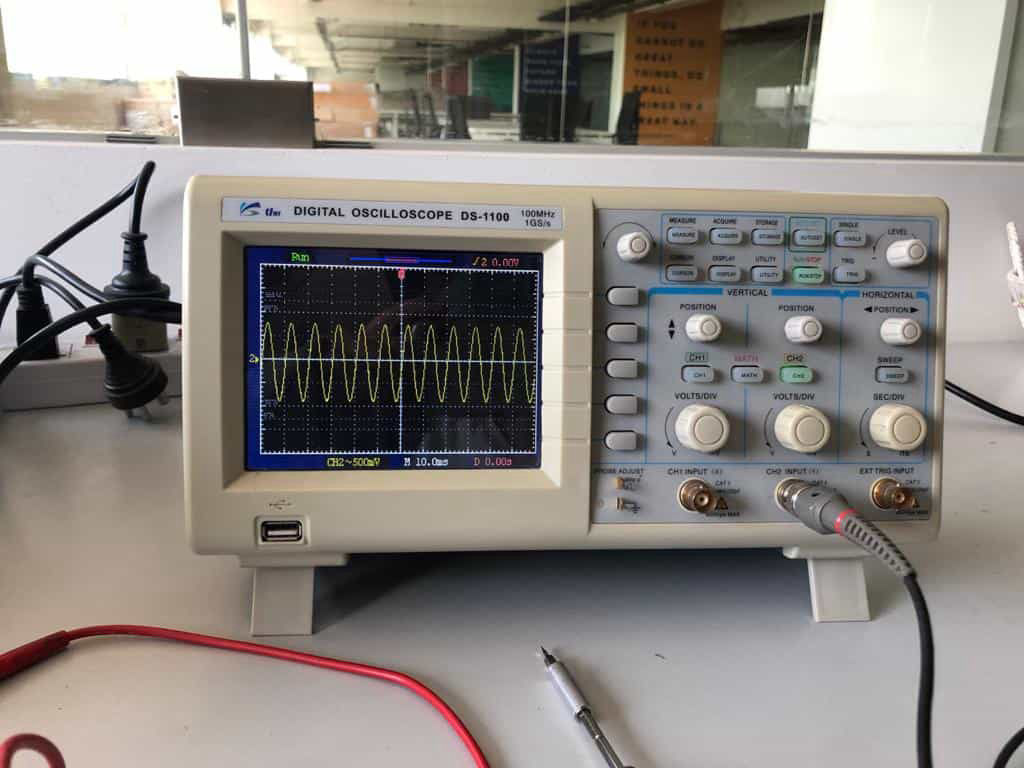
This is used to find see the frequency at which resonator was working and also the led on off signal was visualized.
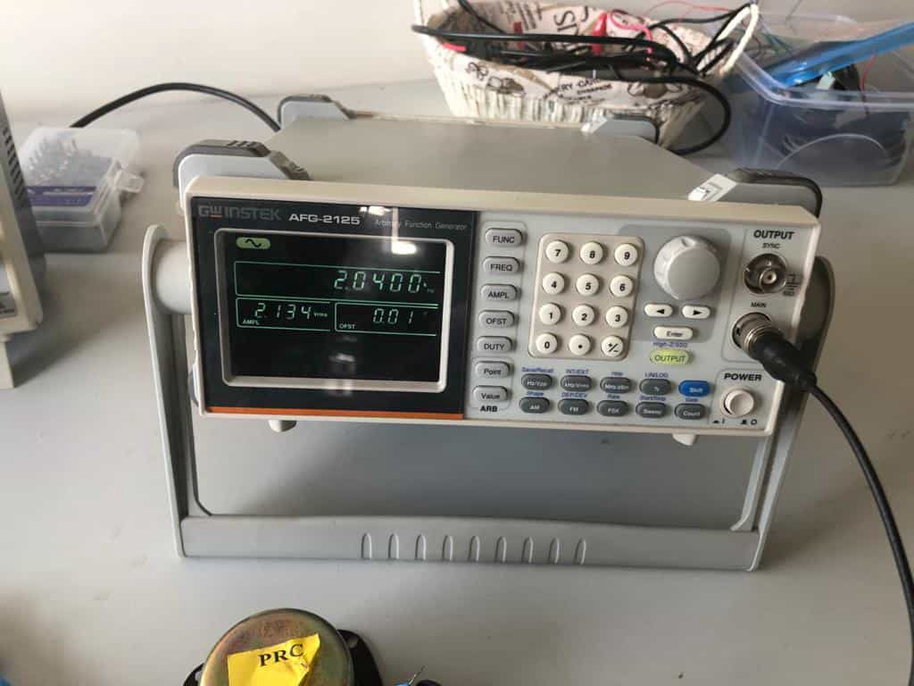
INSTEK AFG-2100/2000 SERIES ARBITRARY FUNCTION GENERATOR
A function generator is a specific form of signal generator that is able to generate waveforms with common shapes. Unlike RF generators and some others that only create sine waves, the function generator is able to create repetitive waveforms with a number of common shapes. The AFG-2100/2000 Series Arbitrary Function Generator is a DDS (Direct Digital Synthesized) based signal generator designed to accommodate the Educational and Basic Industrial requirements for an accurate and affordable signal source covering the output of Sine, Square (Pulse), Ramp (Triangle), Noise and Arbitrary waveforms.
Created with Mobirise