Week 9: Mechanical Design & Machine Design
It’s getting a bit old for me to say that I was excited at the beginning of the week, but that was definitely the case for machine week. When we started brainstorming ideas, I immediately suggested that we develop a motorized camera slider. I have always wanted to build one, and this was the perfect time to do it, as the camera slider could add some production quality to our final project documentation videos in the form of some smooth b-roll footage.
Mar 26
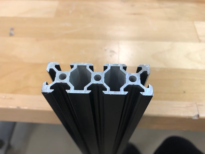
We met in person at the 3D Experience Lab to discuss the assignment, and decided that the camera slider idea was relatively simple, but still had enough sub-components for all of us to work on individual components. Another advantage is that some of the key components we would need, such as the aluminum extrusion to serve as the main body of the slider, could be purchased through OpenBuilds, which makes components for open-sourced hardware projects.
We referenced the designs of numerous camera sliders that had already been built, including those made by Fab Lab Cairo, Isaac897, RZTronics, and How To Mechatronics.
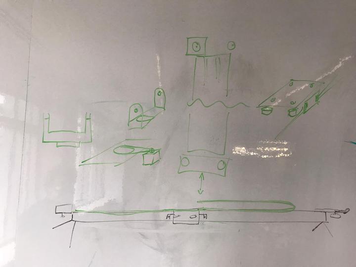
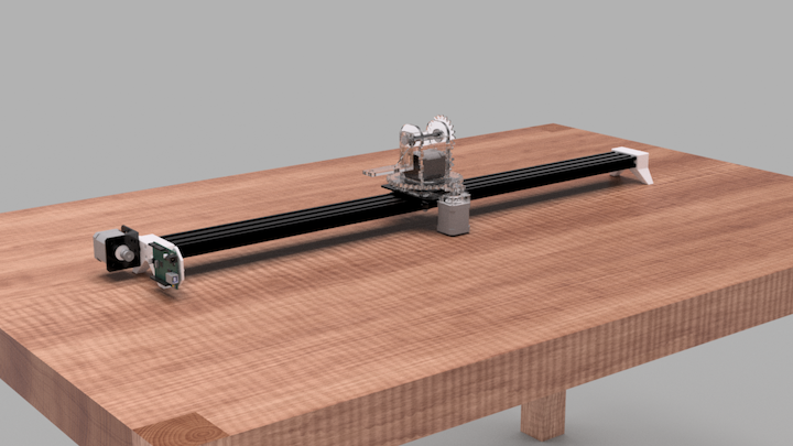
We then began to sketch out designs on the white board. There were several decisions to make, including the motor placement, the pan-tilt head design, and the control system. We decided to have the slider-axis stepper motor mounted to one end of the extrusion, with an idler wheel at the other end of the extrusion, and a timing belt connecting the pan-tilt head to the motor by a toothed pulley. We decided to have the pan-tilt head support the phone / camera mount on one side, rather than making a cradle to support the mount on either side. Finally, for the sake of simplicity we decided to send code to the Arduino controlling the motors directly from a computer, rather than trying to create a user interface with a LCD screen or Bluetooth connection.
With the design mostly finalized, we split the project into sections for each member to work on. I would work on the the slider itself, Nick would work on the pan-tilt head, Xiaolin would work on the phone mount, and Jonathan would work on the coding.
I created a shared Fusion 360 document to begin development of the CAD design. Luckily, OpenBuilds makes 3D models of most of their products available on their GrabCad page, so we could ensure the dimensional accuracy of the design before the parts arrived. This also helped us determine which OpenBuilds parts we would need. We placed an order for the aluminum extrusion, the mounting plate and v-wheels, the pulleys, the idler wheels, the belt, and the drag chain.
Mar 27
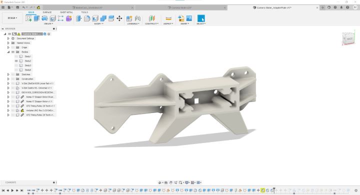
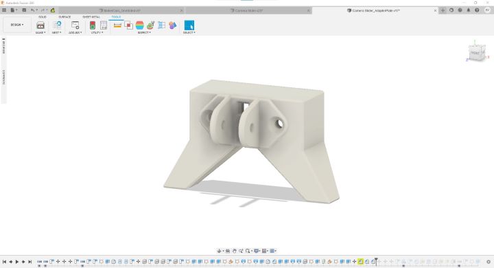
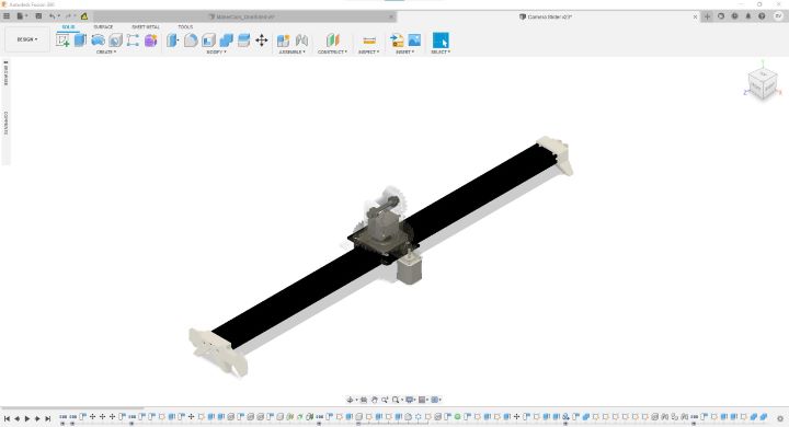
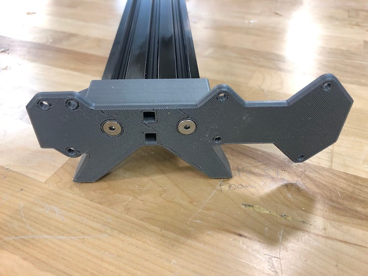
I began integrating 3D models from the off-the-shelf components, and designing the rest of the components around them in Fusion 360. For the linear axis, the two essential components were the two legs that would raise the the slider off the ground. One leg served as a mounting point for the stepper motor and arduino, and the other leg served as a mounting point for an idler wheel. Both legs incorporated holes for the drive belt to be routed close to the extusions. For the idler wheel leg, I split the component into two parts, so they can both be oriented to print without supports.
Camera Slider Files
Around this time, we also learned that our order from OpenBuilds had been delayed, forcing the team to focus on the pan-tilt head for the project presentation.
Apr 7
Nick, Xailin, and Jonathan did a great job working with the pan-tilt head to get it to a working condition by the deadline. I presented the current state of our group project during class time.
The group project documentation and video can be found here
Nick’s documentation can be found here, Xaoilin’s here, and Jonathan’s here.
Apr 12
The OpenBuilds order finally arrived, and I got to work assembling the linear axis. The first step was to tap the holes in the extrusion, so I could attach the legs to it.
The lab had a tap set, but no handle for the taps, so I made one from two vice grips.
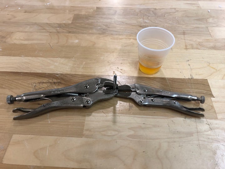
I used multi-purpose cutting oil to lubricate the tap and extrusion while tapping it.
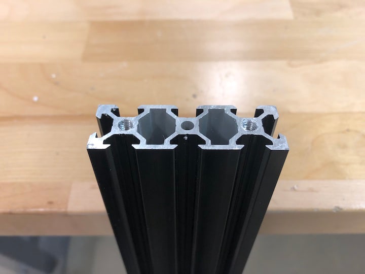
With the extrusion tapped, I was able to fit the leg that housed the stepper motor to the extrusion.
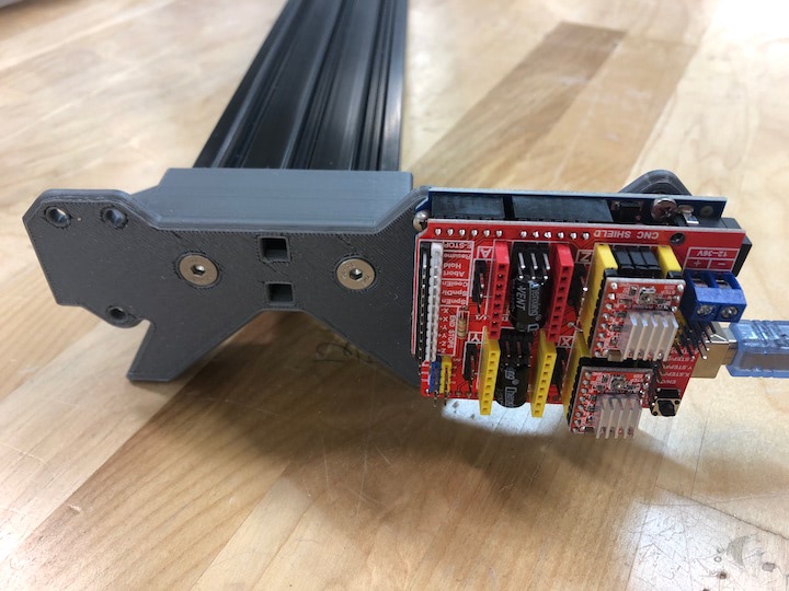
I then mounted the Arduino to the assembly.
At this moment, I realized that the CNC kit we were using didn’t include a stepper motor bracket, so I cried and ordered one.
Apr 19
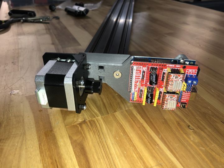
The motor mount arrived, and I was able to get the stepper motor attached to the slider leg.
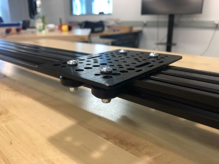
Unfortunately, I hit another snafu. The longest M5 bolts we had at the lab were too short to allow the wheels to attach to the extrusion properly, and would cause the mounting plate to interfere with the extrusion. I cried again, and ordered the proper fasteners.
Jun 11
Fasteners in hand, I returned to the lab to present my final project. Once I finished presenting, I swapped out the hardware, and confirmed that the mounting plate could now properly interact with the extrusion.
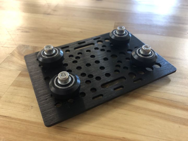
Once this was finished, Nick attached the pan/tilt head on to the mounting plate, and I ran the belt in a loop between the stepper motor and the idler pulley, attaching it to the mounting plate through the machined slots, and securing it to itself with zip ties.
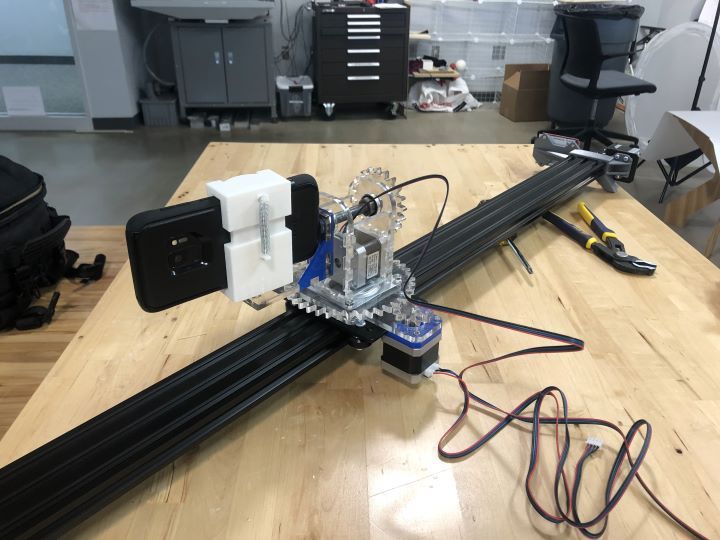
Once everything was assembled, I hooked up the motors to the stepper shield on the Arduino and ran the code that Nick and Jonathan created.
I cried tears of joy.