Week 13: Networking and Communications
I got a late start to this week, and I know that my time is limited, so I tried my best to move as quickly as possible. I got a bit bogged down in making modifications to my circuit board from Week 12, but I was still able to achieve the goals I set out to accomplish.
Apr 28
Neil gave a lecture about interfaces, but it was hard to retain much of the information, as I was still focused on output week.
Apr 29
At our local node meeting, I discussed my plans for the interface week with Greg. I decided to focus my efforts on getting the data from the MPU-6050 inertial measurement unit (IMU) transmitting to the Arduino IDE serial monitor, then getting that serial data to print on the OLED display. Once I got those up and running, I would attempt to transmit serial data over Bluetooth.
May 1
Once I had finished my experiments with the board I had created for week 12, I set out to make a couple modifications to it. This included running 5 volts to the RGB LED, putting the motor and buzzer on a breakout board, and adding mounting holes.
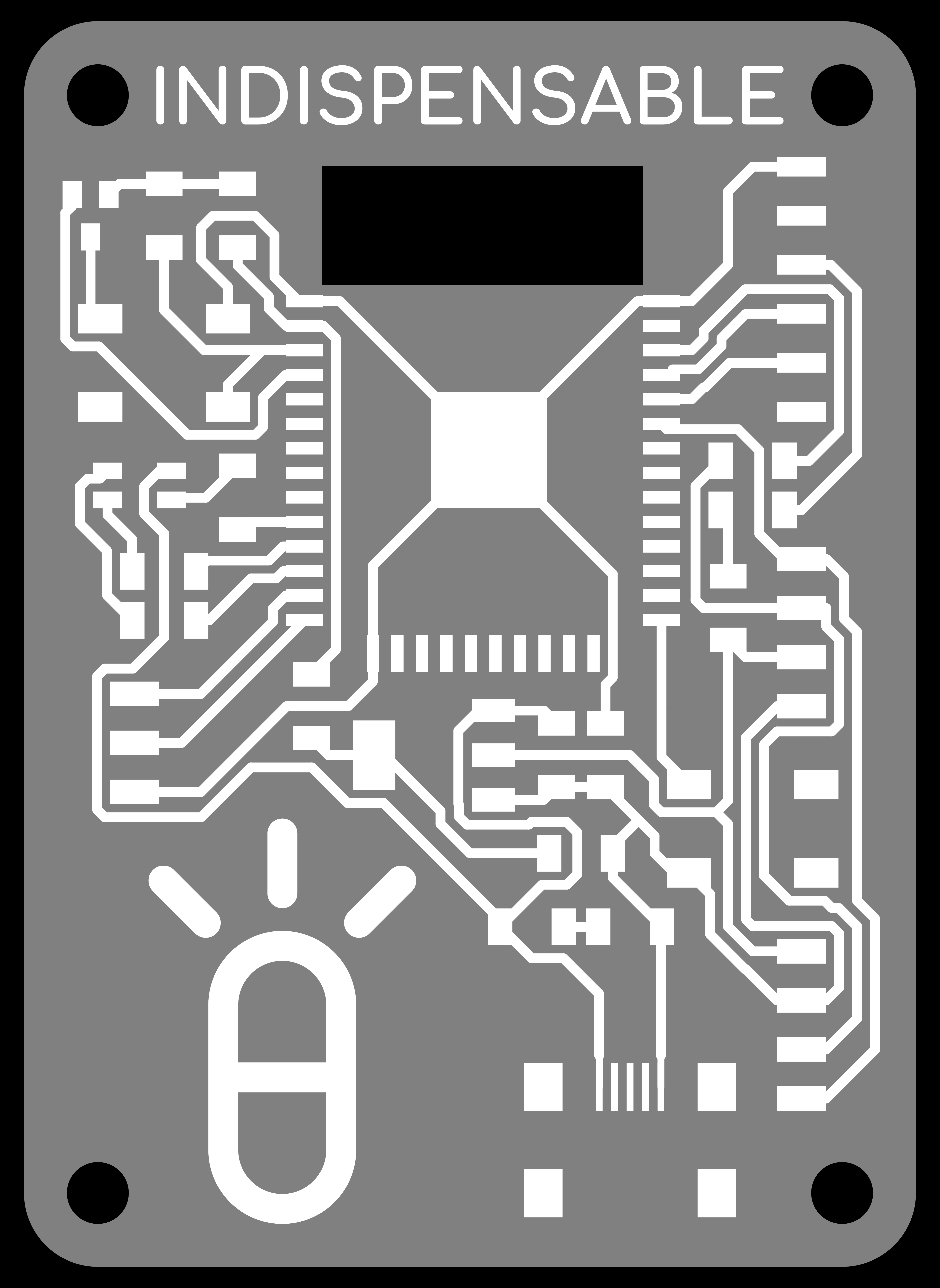
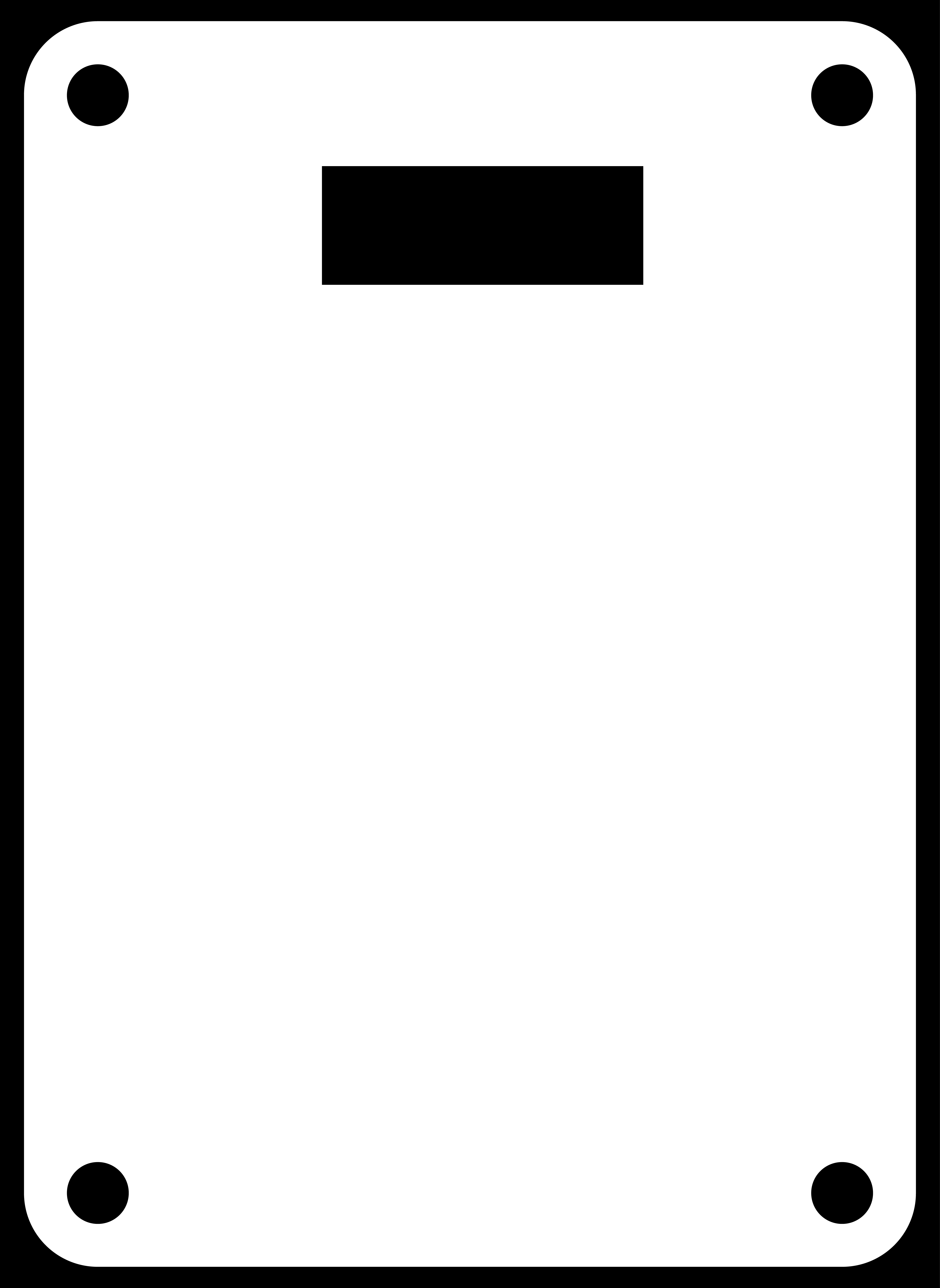
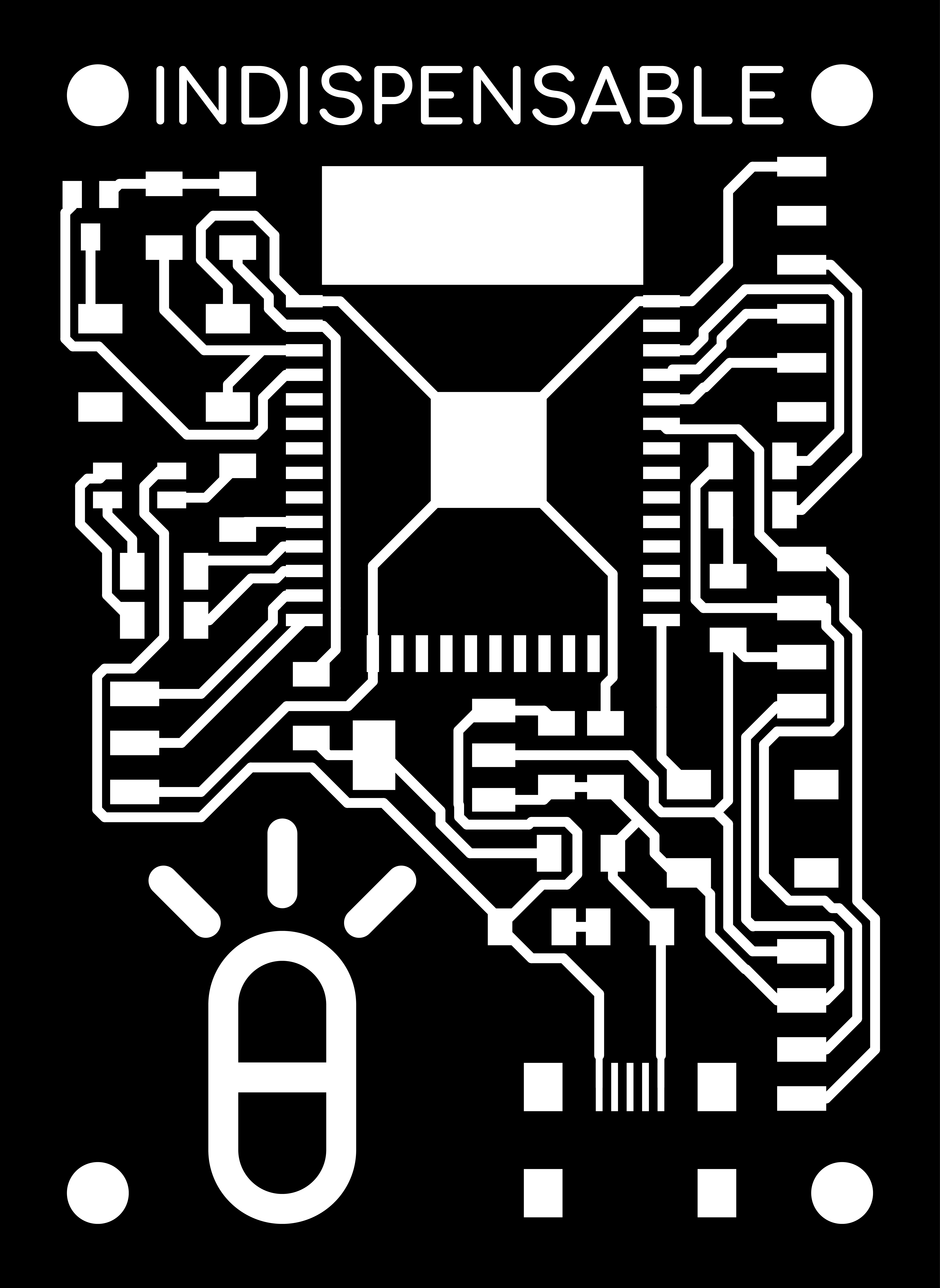
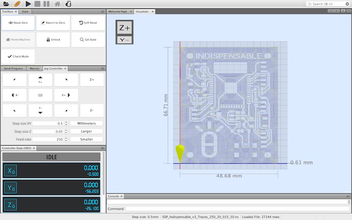
Once I had made these modifications, I uploaded the .png files to Mods to create the g-code toolpaths. I used a large number of offsets in order to clear the entirety of the disconnected copper from the front face of the board.
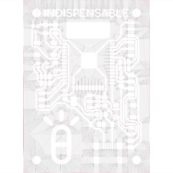
I then uploaded this file to UGS and milled out the board using my 3018 CNC mill.
Unfortunately, I accidentally damaged the pads for the OLED display during the soldering process, which limited the usefulness of this board for this week’s assignment.
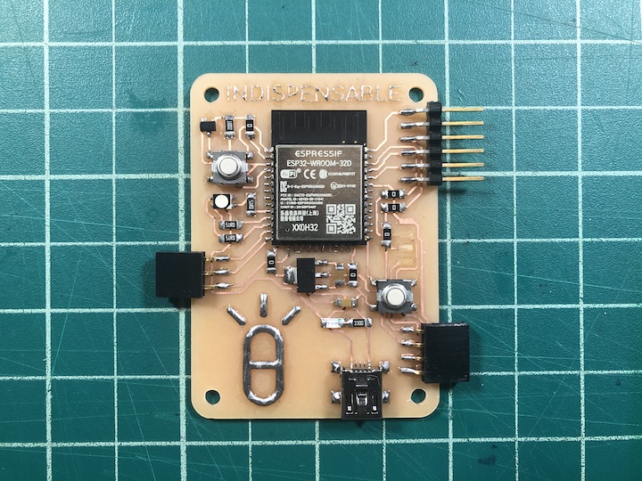
The show must go on, and I continued my tests with the board I milled for Week 12.
May 2
I began to work with the GY-521, the breakout board that houses the MPU-6050 6-DoF inertial measurement unit (IMU). I referenced this page from RandomNerdTutorials to help me get started.
I added the “Adafruit MPU6050” library to the Arduino IDE, and loaded the “basic_readings” example sketch.
#include <Adafruit_MPU6050.h>
#include <Adafruit_Sensor.h>
#include <Wire.h>

Adafruit_MPU6050 mpu;

void setup(void) {
  Serial.begin(115200);
  while (!Serial)
    delay(10); // will pause Zero, Leonardo, etc until serial console opens

  Serial.println("Adafruit MPU6050 test!");

  // Try to initialize!
  if (!mpu.begin()) {
    Serial.println("Failed to find MPU6050 chip");
    while (1) {
      delay(10);
    }
  }
  Serial.println("MPU6050 Found!");

  mpu.setAccelerometerRange(MPU6050_RANGE_8_G);
  Serial.print("Accelerometer range set to: ");
  switch (mpu.getAccelerometerRange()) {
  case MPU6050_RANGE_2_G:
    Serial.println("+-2G");
    break;
  case MPU6050_RANGE_4_G:
    Serial.println("+-4G");
    break;
  case MPU6050_RANGE_8_G:
    Serial.println("+-8G");
    break;
  case MPU6050_RANGE_16_G:
    Serial.println("+-16G");
    break;
  }
  mpu.setGyroRange(MPU6050_RANGE_500_DEG);
  Serial.print("Gyro range set to: ");
  switch (mpu.getGyroRange()) {
  case MPU6050_RANGE_250_DEG:
    Serial.println("+- 250 deg/s");
    break;
  case MPU6050_RANGE_500_DEG:
    Serial.println("+- 500 deg/s");
    break;
  case MPU6050_RANGE_1000_DEG:
    Serial.println("+- 1000 deg/s");
    break;
  case MPU6050_RANGE_2000_DEG:
    Serial.println("+- 2000 deg/s");
    break;
  }

  mpu.setFilterBandwidth(MPU6050_BAND_21_HZ);
  Serial.print("Filter bandwidth set to: ");
  switch (mpu.getFilterBandwidth()) {
  case MPU6050_BAND_260_HZ:
    Serial.println("260 Hz");
    break;
  case MPU6050_BAND_184_HZ:
    Serial.println("184 Hz");
    break;
  case MPU6050_BAND_94_HZ:
    Serial.println("94 Hz");
    break;
  case MPU6050_BAND_44_HZ:
    Serial.println("44 Hz");
    break;
  case MPU6050_BAND_21_HZ:
    Serial.println("21 Hz");
    break;
  case MPU6050_BAND_10_HZ:
    Serial.println("10 Hz");
    break;
  case MPU6050_BAND_5_HZ:
    Serial.println("5 Hz");
    break;
  }

  Serial.println("");
  delay(100);
}

void loop() {

  /* Get new sensor events with the readings */
  sensors_event_t a, g, temp;
  mpu.getEvent(&a, &g, &temp);

  /* Print out the values */
  Serial.print("Acceleration X: ");
  Serial.print(a.acceleration.x);
  Serial.print(", Y: ");
  Serial.print(a.acceleration.y);
  Serial.print(", Z: ");
  Serial.print(a.acceleration.z);
  Serial.println(" m/s^2");

  Serial.print("Rotation X: ");
  Serial.print(g.gyro.x);
  Serial.print(", Y: ");
  Serial.print(g.gyro.y);
  Serial.print(", Z: ");
  Serial.print(g.gyro.z);
  Serial.println(" rad/s");

  Serial.print("Temperature: ");
  Serial.print(temp.temperature);
  Serial.println(" degC");

  Serial.println("");
  delay(500);
}
Ensuring that the baud rate in the terminal was the same as the one set in the sketch, I could then get a live readout of the data coming from the MPU-6050!
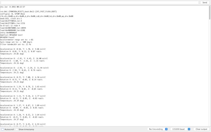
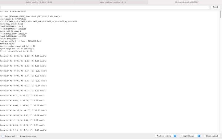
Once this was up and running, I made some tweaks to this sketch to simplify the data coming through to the terminal, as I am only interested in the gyroscope data.
I then moved on to incorporate the OLED display. I referenced this page from RandomNerdTutorials, and loaded the “MPU6050_oled” sketch from the Adafruit MPU6050 library.
Again, I modified this sketch to minimize the data that is output to the OLED, and make it more readable.
#include <Adafruit_MPU6050.h>
#include <Adafruit_SSD1306.h>
#include <Adafruit_Sensor.h>

Adafruit_MPU6050 mpu;
Adafruit_SSD1306 display = Adafruit_SSD1306(128, 32, &Wire);

void setup() {
  Serial.begin(115200);
  // while (!Serial);
  Serial.println("Indispensable Pill Case - MPU6050 & OLED Test");

  if (!mpu.begin()) {
    Serial.println("Sensor init failed");
    while (1)
      yield();
  }
  Serial.println("Found a MPU-6050 sensor");

  // SSD1306_SWITCHCAPVCC = generate display voltage from 3.3V internally
  if (!display.begin(SSD1306_SWITCHCAPVCC, 0x3C)) { // Address 0x3C for 128x32
    Serial.println(F("SSD1306 allocation failed"));
    for (;;)
      ; // Don't proceed, loop forever
  }
  display.display();
  delay(500); // Pause for 2 seconds
  display.setTextSize(1);
  display.setTextColor(WHITE);
  display.setRotation(0);

  display.clearDisplay();
  display.setCursor(0, 0);
  display.print(" ");
  display.println("*** INDISPENSABLE ***");
  display.println("******PILL CASE******");
  delay(1000);

}

void loop() {
  sensors_event_t a, g, temp;
  mpu.getEvent(&a, &g, &temp);

  display.clearDisplay();
  display.setCursor(0, 0);

  Serial.print("Gyroscope ");
  Serial.print("X: ");
  Serial.print(g.gyro.x, 1);
  Serial.print(" rps, ");
  Serial.print("Y: ");
  Serial.print(g.gyro.y, 1);
  Serial.print(" rps, ");
  Serial.print("Z: ");
  Serial.print(g.gyro.z, 1);
  Serial.println(" rps");

  display.println("*** INDISPENSABLE ***");
  display.print("       X: ");
  display.print(g.gyro.x, 1);
  display.println("");
  display.print("       Y: ");
  display.print(g.gyro.y, 1);
  display.println("");
  display.print("       Z: ");
  display.print(g.gyro.z, 1);

  display.display();
  delay(100);
}
May 3
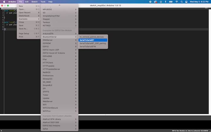
Having accomplished the MPU6050 and OLED components of my week’s goals, I turned my attention to the Bluetooth aspect. With the ESP32 Dev Module selected as the board in the Tools tab, I opened SerialToSerialBT from the BluetoothSerial tab in the Examples tab.
Once compiled, I uploaded this sketch to the board through the FTDI port.
#include "BluetoothSerial.h"

#if !defined(CONFIG_BT_ENABLED) || !defined(CONFIG_BLUEDROID_ENABLED)
#error Bluetooth is not enabled! Please run `make menuconfig` to and enable it
#endif

BluetoothSerial SerialBT;

void setup() {
  Serial.begin(115200);
  SerialBT.begin("ESP32test"); //Bluetooth device name
  Serial.println("The device started, now you can pair it with bluetooth!");
}

void loop() {
  if (Serial.available()) {
    SerialBT.write(Serial.read());
  }
  if (SerialBT.available()) {
    Serial.write(SerialBT.read());
  }
  delay(20);
}
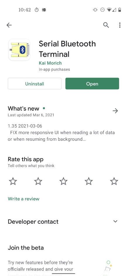
I downloaded a Bluetooth serial monitor app to my iPhone, but I was unable to detect the ESP32’s Bluetooth signal. I borrowed my sister’s Android phone and downloaded the Serial Bluetooth Terminal app from the Google Play Store.
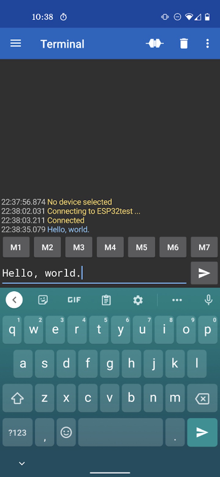
The ESP32 appeared on the list of Bluetooth devices, and I selected it to established a connection to the phone.

Once the two devices were connected, I opened the serial monitor in the Arduino IDE on the laptop that the ESP32 was connected to. I then typed “Hello, world.” into the Serial Bluetooth Terminal on the Android phone, and the message appeared in the serial monitor on the laptop!
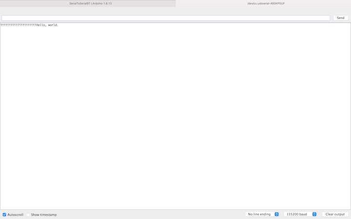
I then typed the same message into the laptop’s serial monitor, and it appeared in the monitor on the phone!