Week 16: Applications and Implications
Disaster struck early in the week, but I was able to make the most of it. Luckily, I was at a point where I needed to bury my head in CAD, and I could manage that on my temporary setup, but being without my computer for an entire week definitely threw a spanner in the works.
May 19
Neil gave an interesting lecture about exciting projects that have grown out of CBA and Fab Academy. Of particular interest to me was the cube-sat he briefly mentioned, as I am a big aerospace nerd.
May 20
While getting work done at Starbucks, my laptop battery failed. I tried a number of troubleshooting steps, but the computer would crash about five minutes after being turned on, no matter how much the battery was charged, or even if the laptop was plugged in.
May 21
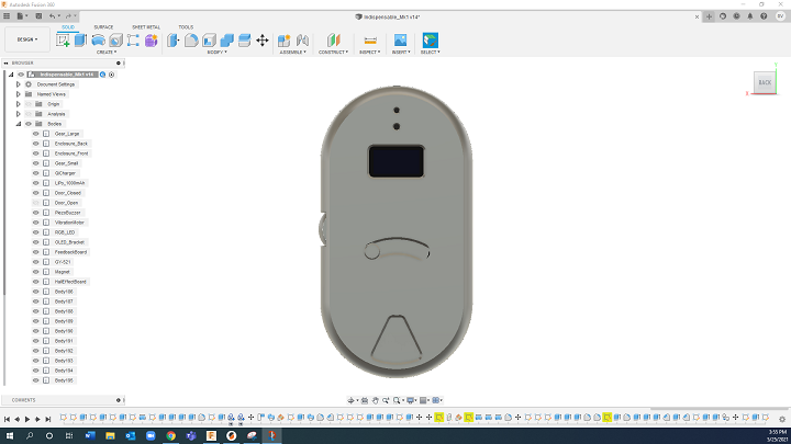
Accepting defeat, I brought my laptop into a repair shop, and began searching for an alternative workstation. Luckily, my generous mother let me use her desktop PC until my laptop was repaired, so I downloaded Fusion 360 onto her desktop and was off to the races. I began by laying out the pill compartment, the drive gear / thumb wheel, the battery, and the OLED display. These are the most prominant components, and my thinking was that once I determined their position, I could fit everything else around them.
Having designed similar pill cases before (minus the electronics), I had a good understanding of the limits of how compact the pill compartments could be while maintaining their usefulness, and how large the case could be without it being too cumbersome. With these parameters in mind, I modeled the components in Fusion 360, and an enclosure that encapsulated them.
May 22
During the Global Open Time, I discussed the current state of my project, and Rico shared a great resource describing supply-side time management.
Now that the enclosure was modeled around the large components, I needed to solve the 3D puzzle of getting everything else to fit inside it. In order to do this, the first step was to create a list of all the components. Luckily, this was part of this week’s assignment, so it was time to do my homework.
What will it do?
- Indespensable is a portable pill case to hold vital medications, remind users to take those pills, and track when the pills are taken. It is designed to replace a standard pill case, so it is assumed that the user can operate a traditional pill case independently, without assistance or intervention.
Who’s done what beforehand?
There are smart pill cases out in the world, such as Pillieve, Hero, and Pillo. Pillieve is a locking pill case designed to limit the consumption of opiods, and Pillo and Hero are counter-top, friendly pill dispenser that essentially serve as a smart medicine cabinet. While these are well designed, useful tools for their target markets, their intended use case is different from the case I have described above.
In 2016, Arsheena E.P. at Fab Lab Kochi built a pill case to remind her grandmother with Alzheimer’s to take her medication on time. In 2017, Corey Rice built a countertop pill dispenser to help his elderly grandmother take her pills on time. Finally, Jasim Bouresli at Fablab Kuwait initially planned to build a Bluetooth-connected pill box, but ended up building a Bluetooth-connected, locking jewelry box. Loes Schakenbos from Waag is currently working on an at-home pill case to sense when her pills have been taken. These FabLab projects give me confidence that my proposed project is not only technically possible, but it is achievable within the timeframe of the course.
What will you design?
- The case itself, the circuit board inside of the case, the code that runs on the board, and the app that connects the case to a phone.
What materials and components will be used? Where will it come from? How much will they cost?
-PLA/PHA filament - $29.99 / kg
-Bearings - $0.62 / bearing
-Neodymium magnets - $0.18 magnet
-1000 mAh LiPo battery - $9.79
-Qi wireless charging receiver - $14.95
-FR1 PCB blank
-ESP32 - $5.40
-JST connectors - $12.99 / kit
-GY-521 - $5.39
-SSD1306 0.96” OLED - $6.99
-Piezo buzzer - $2.62 / buzzer
-Vibration motor - $1.17 / motor
-Hall-effect sensor
-Nylon fasteners - $11.88 / kit
What parts and systems will be made?
-Pill case enclosure
-Pill case PCBs
-Mobile app
What processes will be used?
-3D printing
-CNC milling
What questions need to be answered?
-LiPo / Qi Charging circuitry
-Triggering state change with gyroscope value
-Sending data from ESP32 to database in app
How will it be evaluated?
-Can the app change the state of the ESP32 to indicate it’s time to take pills?
-Can the sensors detect that the pills have been taken?
-Can the ESP32 send that data back to the app to let it know the pills have been taken?
-The functional component will be fairly straightforward to evaluate, but the most important, and difficult component to evaluate will be the emotional design component. I hope to consult with mentors in the emotional design and affective computing communities to better evaluate this aspect.
May 23
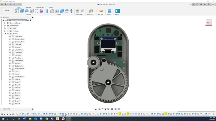
Now that I had all of my components itemized, I could begin fitting them inside the enclosure. I knew that this would take a long time, and I was right. I’m still not finished.
May 25
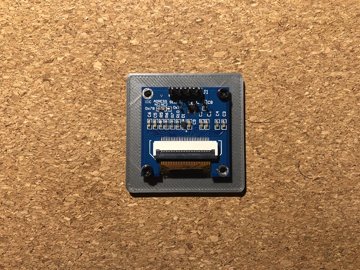
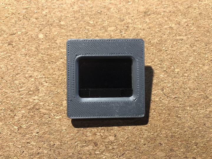
My SD card reader and M2 fasteners arrived in the mail, so I begin some test prints. The first one was to see if I could use the M2 holes in the OLED display to mount the OLED directly to the enclosure, or if I wouldn’t be able to print functional threads of that size. If the test failed, I would need to use a bracket to hold the OLED in place, and attach the bracket to the enclosure with M3 fasteners. This would be significantly more bulky, which would be sub-optimal.
The first test was a failure, but I used Fusion’s “Offset Face” feature to increase the size of the threaded hole to account for the over-extrusion of the printer. This second test was a huge success, meaning I don’t need to use a bracket to mount the OLED.
The next test print was to confirm that the gears interact properly. Each gear has two bearings attached to it, and sits on a shaft with a threaded hole through its center.
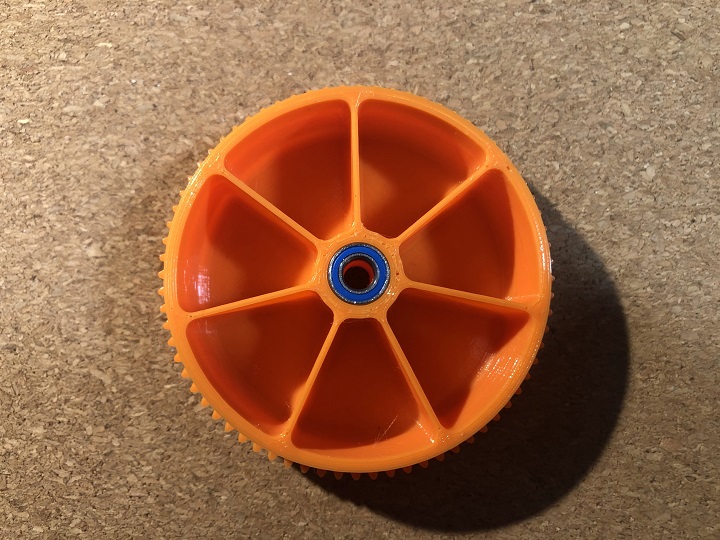
I printed out both gears, and noticed a few issues. One issue that was easy to fix was that the void to house the lower bearing was slightly too shallow, most probably due to the bridging filament sagging on top of its supports. I measured that the lower bearing is 0.4mm proud of the lower face of gear on both the small and large gear. The other issue was that the teeth don’t fully interlock. I suspect that this also has to do with the lower edge of the teeth on the large gear being printed on top of supports, which don’t do their job 100% perfectly, so the lower edge of the teeth doop, making them wider, and not fitting into the teeth of the small gear. This is also a simple fix of adjusting the width of the teeth to account for the dimensional innacuracy.