Week 6: Electronics Design
This week’s topic is especially helpful to my professional development. My company designs and sells circuit boards, but I mainly focus on other aspects of the business, and haven’t gotten around to learning the PCB design workflow. This week forced me to finally learn these skills, which will help me shape the direction of my company’s development. I mainly do my CAD work with Fusion 360, and my business partner uses Eagle, so doing this week’s assignment in Eagle was a natural choice.
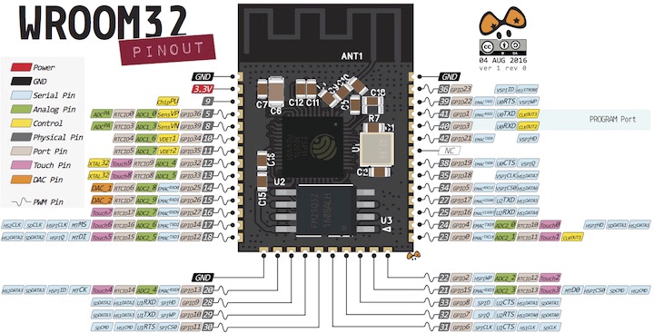
This week was ultimately yet another exercise in reducing my lofty ambitions to something manageable for the given timeframe. I was eager to make progress on my final project, and I intend to incorporate the ESP32 microcontroller, so I planned on making an ESP “hello world” board for Week 6. While I eventually had to settle for a simpler board, I learned a lot about the PCB design workflow, the quirks of Eagle, and what hurdles would need to be overcome in order to work with the ESP32 for my final project.
Mar 4
Greg gave a great electronics introduction and Eagle tutorial during our local node session. To prepare for this week’s assignment, I reviewed the recording of this lecture, along with text tutorials from the Fab Academy site and FabCloud.
Mar 6
During the Global MCU, I asked for the group’s opinions and past experiences working with the ESP32. Adrian pointed me to the documentation for the Barduino, which is a fab-able ESP32 breakout board. Both this board, and the ESP32 “hello world” board in the Fab Academy Embedded Programming page use the ESP32 WROOM32D, so I ordered a 5-pack of these chips from Amazon.
I was also directed to this tutorial for working with the ESP32.
Mar 7
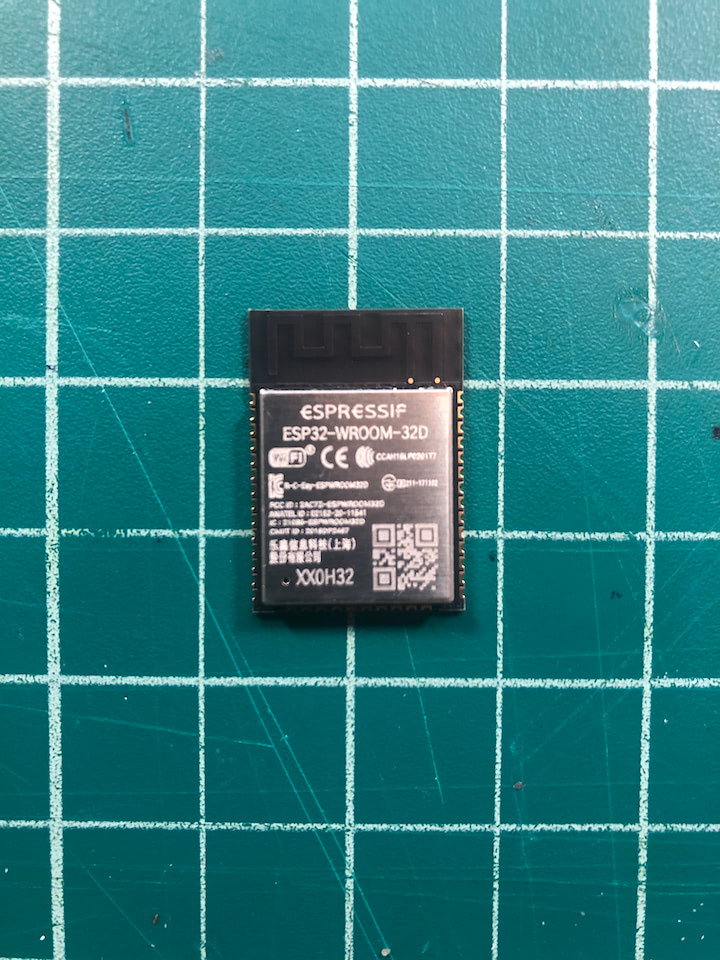
The ESP32s arrived incredibly quickly.
I downloaded Eagle so I could begin to design the “hello world” board. I also downloaded the Eagle fab library that includes Eagle-compatible part files for all components in the fab kits. This download was a .lbr file that I had to drag and drop into my “EAGLE” folder in Documents for it to appear as a library in Eagle.
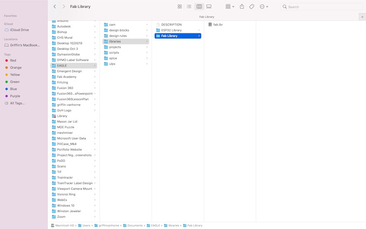
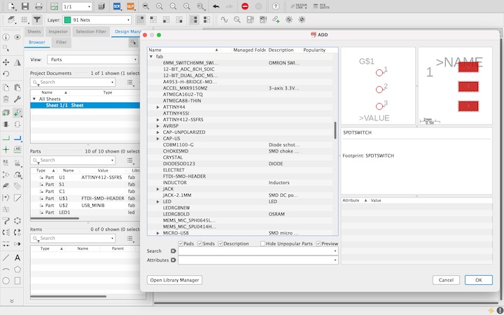
Following the Barduino documentation, I also downloaded the ESP32 library and added it to the EAGLE folder following the same steps. I created a new project file and a new schematic file to go inside it. Once in the schematic workspace, I could begin populating the schematic. First, I needed to include the fab library into the schematic…
Then I could simply click the “add part” button and select the “fab” dropdown to access all files in the library.
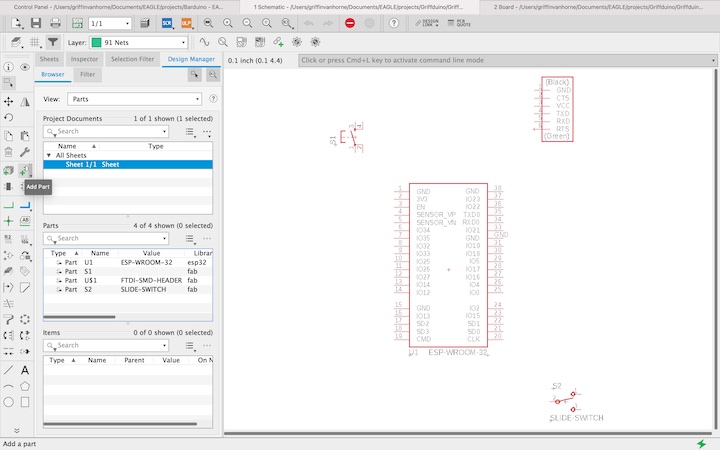
Once all necessary components were in the schematic, I could could use the “net” tool to create wires to the pins that will need to be routed, and use the “name” tool to identify where the pin will be connected.
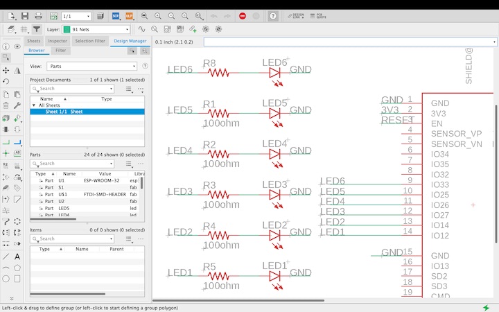
Rather than connecting the two pins directly by a “net,” I could simply just create small nets on the pins and label them with the same name, and they will still be connected by “airwires” when I enter the “board” workspace. This workflow simplified the process of getting a design ready quickly, but I can see how it would be helpful to build a functional schematic with all nets directly connected before entering the board workspace. Once all of the nets were labeled, I entered the board workspace and positioned the components in the center of the frame.
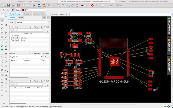
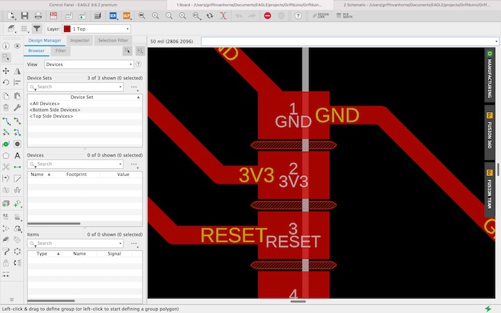
The thin yellow lines in the design are “airwires,” which indicate that the pins they connect were given the same label in the schematic. The goal in the board workspace is to lay out the components and the “route airwire” tool to connect any pins with airwires between them with traces in order to get the most efficient design possible. There are several tricks that can be used to make designs simpler and create shorter traces, including using components such as resistors and capacitors to “jump” over other traces, acting as a bridge.
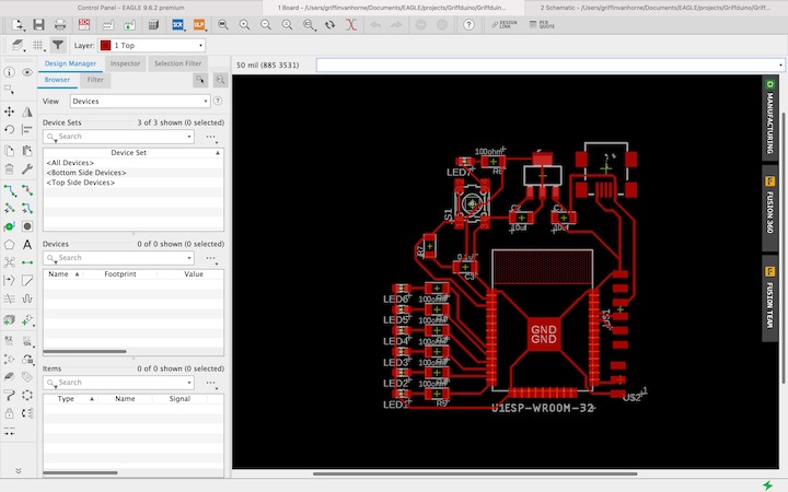
Once all airwires were routed, it was time to run my design rules check to ensure that there were no glaring errors with my design. In this case, the board was going to be milled on the 3018, so I downloaded the fab design rules and ran a check to ensure that the design was compatible with the manufacturing techniques. Unfortunately, the check revealed that the pads of the ESP32 were too close together for a 1/64” endmill to fit between them, so if the file were exported to Mods, no tool paths would be generated to separate the pads.
Interestingly, the “traces” .png file in the Barduino documentation appears to show wider gaps between the pads, but there is no mention of this issue with the ESP32 footprint listed in their documentation, or of any modifications made to the file to make it compatible with the manufacturing techniques we are using. While I did find an article on how to customize the component’s footprint in Eagle, this issue was a bit more than I could overcome in the given timeframe, and I unfortunately had to shelf the ESP32 hello world board in favor of something a bit simpler.
Mar 9
Now with significantly limited time to complete the assignment, I decided to follow Greg’s Eagle tutorial to create a hello world board for the ATTiny412.
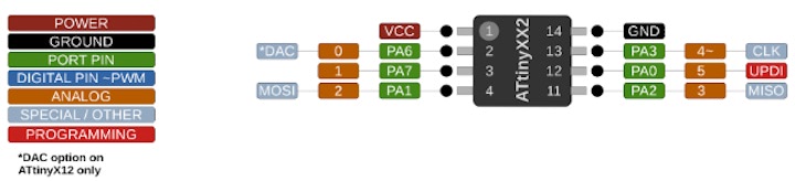
Neil’s ATTiny412 board schematic, trace, and interior files can be found in the Fab Academy Embedded Programming documentation. Building off this design, I included a LED to indicate when the board is receiving power, a programmable LED, and a mini USB to supply power to the board once it’s programmed so I don’t need to keep it next to the programmer to demonstrate its function.
In order to add the ATTiny412 files to the fab library, I had to first download them from UltraLibrarian. While the download does include instructions on how to add the package as a new library, I followed Greg’s instructions on how to add the part into the existing fab library.
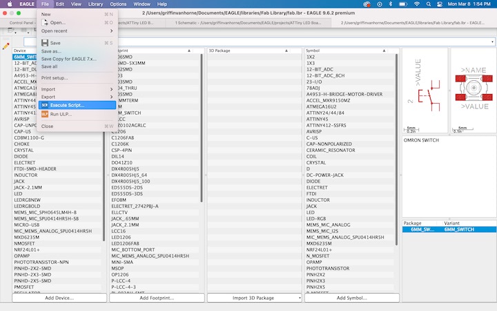
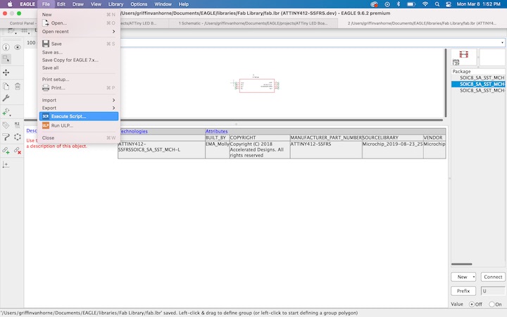
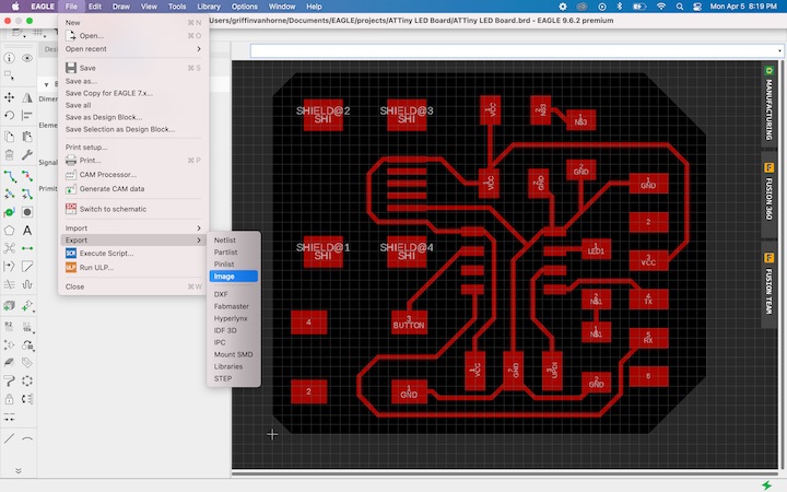
Once the ATTiny was included in the fab library, the process for creating the schematic and board files was the same as the process described for the ESP32 board, and it went very quickly, as the board was much simpler. I went into the “layer settings” tab and turned off all layers except for the top layer, and exported the file as a .png file, being sure to select the “Monochrome” option in the Export panel.
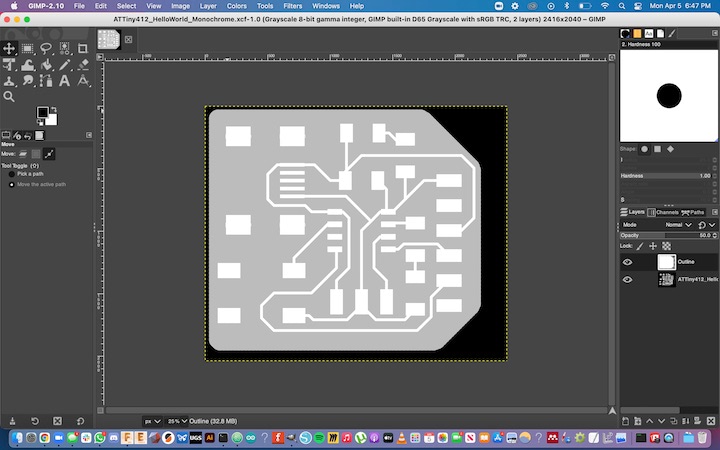
I then opened this file up in GIMP, created a new layer on top of the traces, and used the pencil tool to draw the perimeter of the board. By holding shift and control, I could draw straight lines the would snap to 45 degree increments, which simplified drawing the perimeter shape. Once the shape was created I filled it in with white, and filled in the alpha background with black. I also turned the opacity down to 50% so I could see the traces underneath the “interior” shape.
I configured the CAM settings for the traces file in Mods and modified the exported file as described in my Week 4 documentation. I began milling out the traces, but quickly realized that there was a scaling issue with the file, causing it to be 2x larger in both axes.
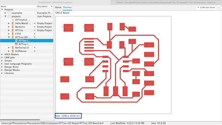
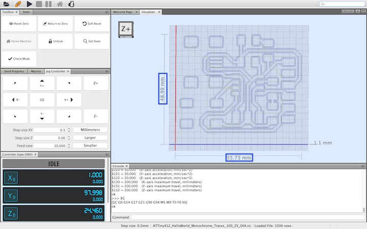
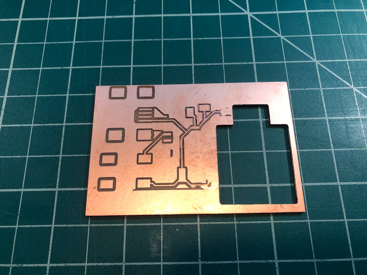
I checked the original dimensions of the file in Eagle, and resized the .png files in GIMP to ensure that they were the proper size. Once resized, I processed the new files in Mods and milled them using the 3018 mill. This was the highest quality board I’ve milled so far.
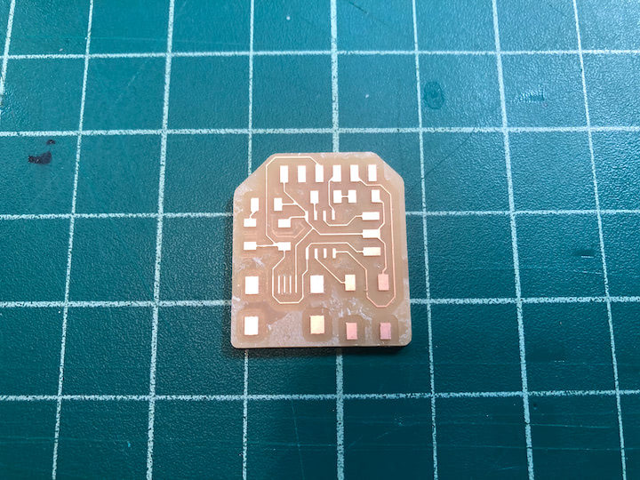
Unfortunately, while cleaning up the copper between the traces, I managed to sever one of the FTDI traces. I later attempted to bridge the gap with solder, but this effort was ultimately unsuccessful. I soldered the components on to the board without incident, using the techniques outlined in my Week 4 documentation.
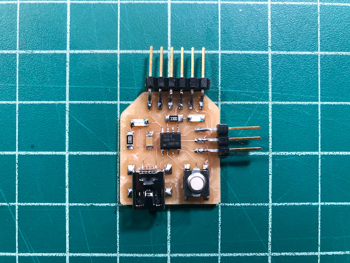
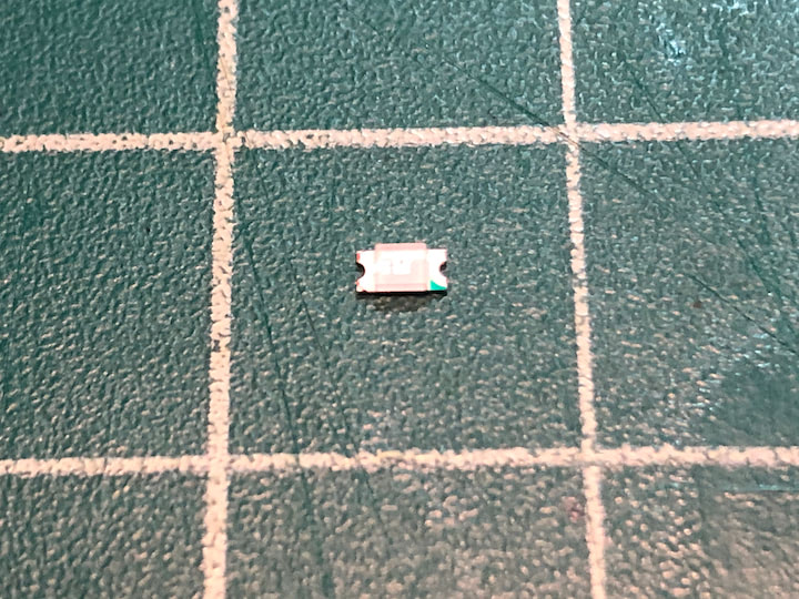
One important point to note about soldering is the the LEDs are polarized, and need to be oriented properly in the board, or they will not function. In order to orient them correctly, I referenced this Sparkfun article on LED polarity and this page by Talking Electronics on SMD LED markings, then matched the the orientation of my SMD LEDs to the orientation of the pads on my schematic file by using the green marking on the LEDs.
ATTiny412 PCB Files:
Mar 11
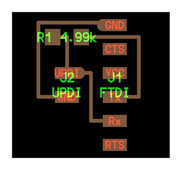
In order to program the board through its UPDI pin, I had to mill a FTDI to UPDI connector so I could use the FTDI programmer provided in the Fab Academy home kit. The files for the traces and perimeter of the board were provided in the Fab Academy Embedded Programming Fab Academy page.
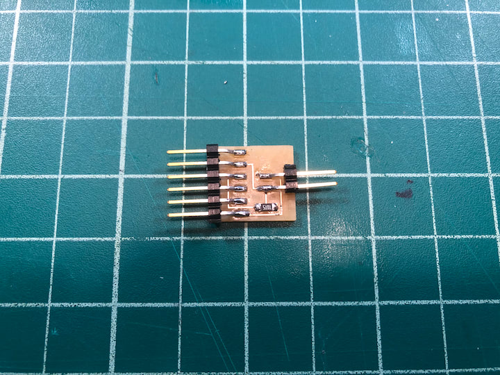
With the files downloaded, I milled the adapter with my 3018 CNC mill using the same process that I have previously documented.
I then used Neil’s ATTiny412 blink.ino sketch as reference to create a “blink” sketch to test my board. The code will make the programmable LED blink twice in rapid succession every second. The code is as follows:
#define LED 4

void setup() {
   pinMode(LED,OUTPUT);
   }

void loop() {
   digitalWrite(LED,LOW);
   delay(700);
   digitalWrite(LED,HIGH);
   delay(100);
   digitalWrite(LED,LOW);
   delay(100);
   digitalWrite(LED,HIGH);
   delay(100);
   }
With the code finalized, I began setting up the Arduino IDE to program the board. I first entered the Preferences menu and entered “http://drazzy.com/package_drazzy.com_index.json” in the “Additional Board Manager URLs” field.

I then clicked on “Tools,” then “Manage Libraries.” When presented with the Library Manager, I searched for the MegaTinyCore library, then pressed “Install.”

With the version 2.2.9 of the library installed, I closed the Library Manager and opened the Tools menu. I selected “Board,” “MegaTinyCore,” then “ATTiny412/402/212/202.”

I then selected “Port” and identified FTDI programmer in the menu as the USB serial port.

I then selected “Programmer” and chose “Serial Port and 4.7k (pyupdi style).”

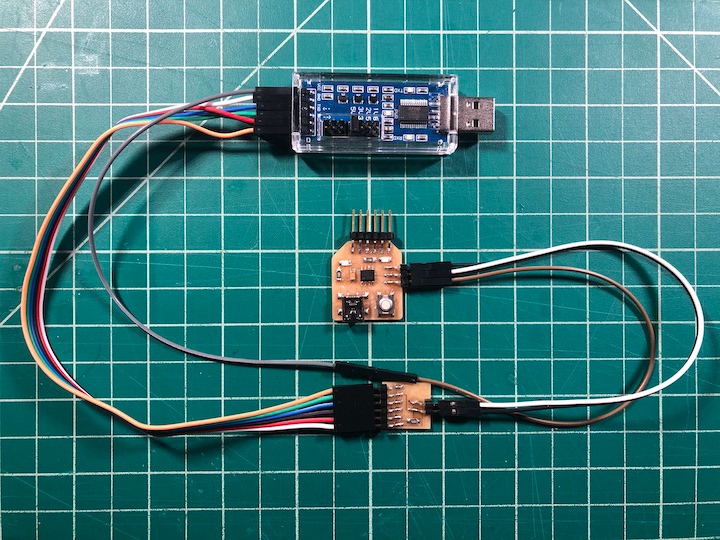
With these settings selected, I connected the FTDI programmer to the UPDI adapter, and the adapter to the ATTiny412 board.
I then verified the sketch and uploaded it to the board. The sketch ran as intended!
Apr 18
To test the voltage drop across the LED while it was blinking, I supplied 5V to the board via the MiniUSB cable and touched the red probe of the multimeter to the LED pin side of the LED, and the black probe to the ground pin side of the LED.
Reviewing the video, it appears that about 1.75 V were flowing across the LED when the LED was on, and about 250 mV were flowing across it when the LED was off.
I followed a YouTube tutorial shared by a classmate to get started using the DS212 digital oscilloscope included in our home kits, but I still had difficulty getting it working.