Planning
We decided to build a 3 axis camera slider. See the full group documentation here. I offered to design and build the Pan/Tilt Stage. Griffin had specified the open builds universal build plate to be mounted on V-wheels to run on the extrusion rail. I had to mount my parts on that. He imported models of the open builds components in Fusion 360 and passed the file along to me to build. I knew we had a kit with 3 NEMA 17 stepper motors so that would be my drive system. For the pan axis I picked out a turntable bearing from Mcmaster-Carr. I started my design by mounting that bearing and the motor and built up from there.
Design
Pan Stage
I needed a plate that would mount the bearing onto the open builds plate and mount the motor off to one side. I also needed a pair of gears to connect the motor to the top side of the bearing. I found a good video tutorial on using the spur gear generator that’s in Fusion 360’s default Add-ons. It made the different parameters very simple and gave a preview of the diameter of the gear that will be output.
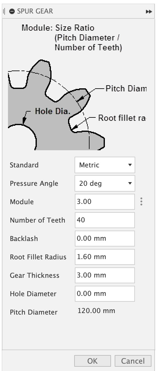
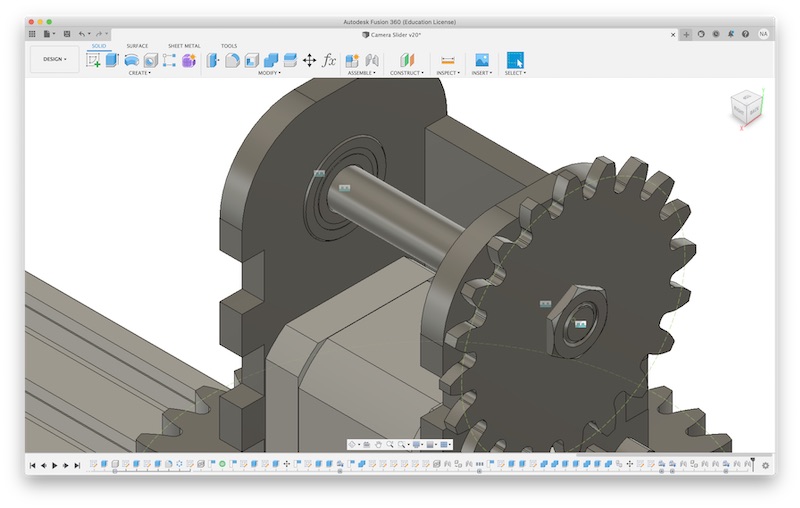
I generated a gear to fit on top of the bearing that would stick out past the edge of the open builds plate slightly. That turned out to be a 40 tooth gear. I then made a 10 tooth gear that would mesh with that. I arbitrarily chose a 1:4 gear ratio. I aligned the two of them and used the center of the smaller gear to position a model of the NEMA 17 stepper motor. I then used the stepper to project a sketch that included the motor mounting, the open builds plate, and the turn table bearing. This allowed me to create a mounting plate for all of those. The motor was hanging under the plate by a bit and two of the mounting holes interfered with the aluminum plate. I made two more layers to fill in the gap and fit some counter sunk screws to secure them in place.

At this point I wanted to test this system before I designed the tilt stage using the same basic principle. After those tests succeeded I moved on to designing the tilt stage.
Tilt Stage
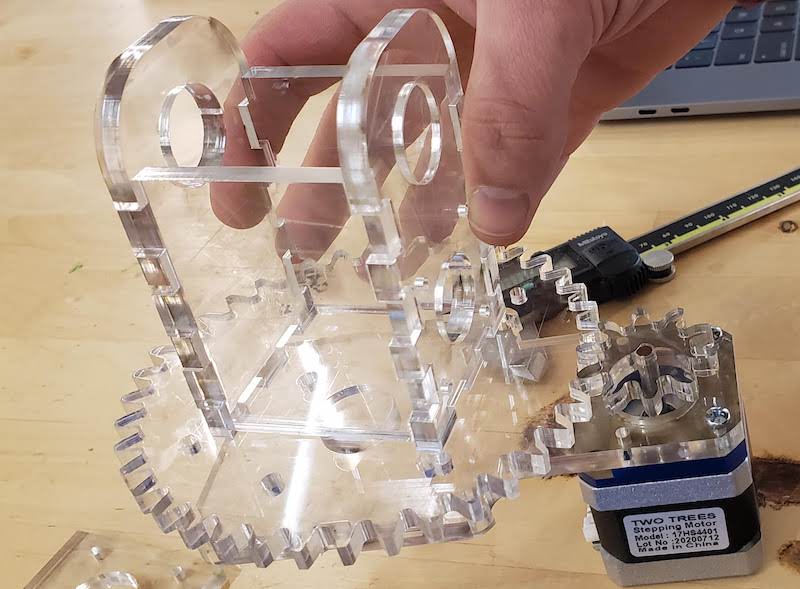
We had initially envisioned a forked tilt mount with a bearing on either side of the camera Xiaolin had sent us an image of a commercial slider that had the tilt mount cantilevered off to one side. I like this better so decided to go in that direction. I added another stepper motor on top of the pan gear and then added a pair of mounts on either side of it that would secure it and a pair of skateboard bearings above it to hold a shaft that the cantilevered arm will pivot on. As soon as I had that part roughed in I cut a test part to see how well the bearing press fit into it. I did do some kerf compensation in the model here instead of shrinking the vector at cut time.
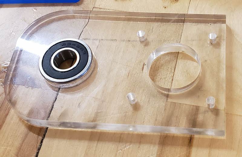
The bearing press fit worked perfectly so I continued with adding tabs and slots to box out that tower. Instead of making that all press fit I decided to just glue these parts together so I didn’t have to do a lot of cuts to refine the fit. I used this as a reson to try some new Fusion 360 tools and use the combine tool to intersect, cut, and join bodies to create the tabs and slots for all 4 sides from a single sketch.
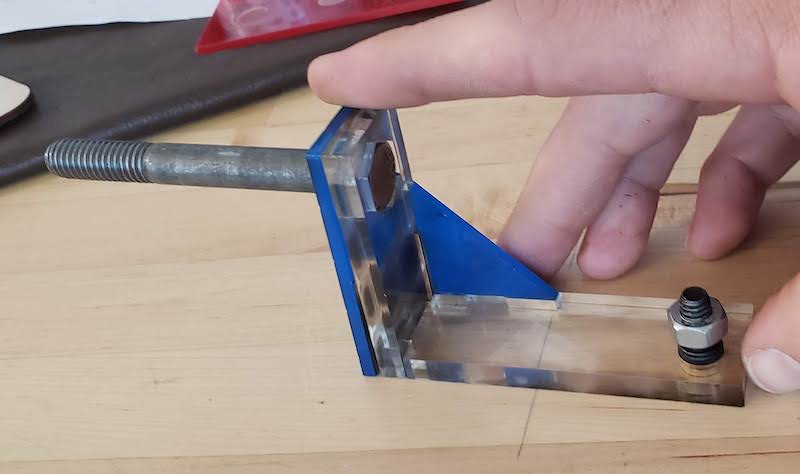
I found a 3/8 x 3 inch bolt that fit the bearings and added that, a nut to fit on it, and two bearings from the Mcmaster-Carr catalog I decided to press fit the drive gear onto the nut and press fit the tilt arm onto the head of the nut. This probabbly isn’t the best plan to put the drive onto a threaded part but I will just lock it with a jam nut and not worry about it. For a one week build it will do. I made another set of gears to transfer power from the motor to the tilt arm. The tilt arm itself is just a simple L with a little triangle to give it some strength I will also be glued together for simplicity. I found a cap head 1/4x20 screw to press fit into the end of the arm as a standard camera mount screw.
Fabrication
Laser Cutting
I modeled the plates and gears as either 3mm or 6mm thick because I knew we had plywood or acrylic in both of those thicknesses. I decided to go with acrylic because I though it would look cooler. I will laser cut all of these parts because it is accurate and fast to iterate. I hadn’t used the laser cutter at the DS lab since laser cutting week a few months ago so I had to relearn a few minor quirks of this software toolchain. See the laser cutter quirks addendum below.
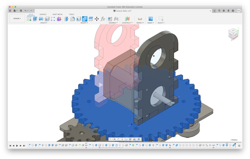
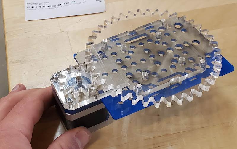
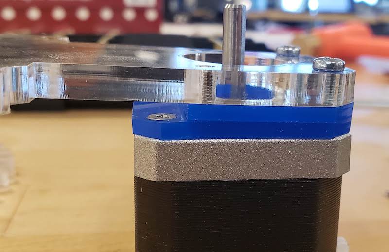
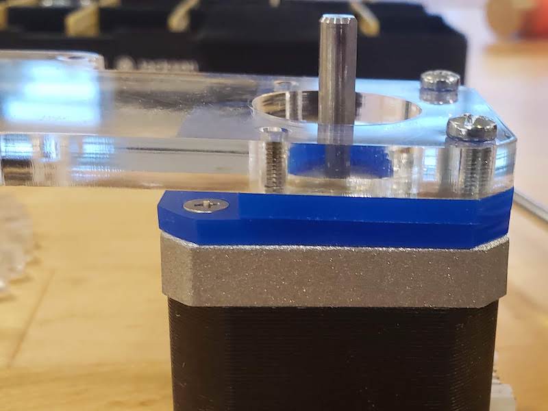
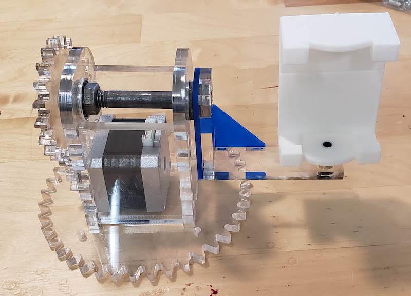
Once I had the laser working correctly I cut the two motor shims out of 3mm acrylic and the main mount and gears from 6mm acrylic. The first try of the gears fit together fine but the motor shaft was a bit loose. I hadn’t done any kerf compensation so this was expected. I wanted to try a quick kerf compensation instead of a measured version so I just selected the motor shaft vector and scaled it by 97% to make it slightly smaller. The re cut gear fit perfectly with a press fit. I grabbed two M3 Screws and mounted the plates and gears. I had also cut a stand in of the OpenBuilds mount plate because all our parts hadn’t been delivered yet. You can see that in blue in the picture below. The turntable bearing hadn’t been delivered yet either so I wasn’t 100% certain all was good but it seemed likely.
Now that I was confident this design and fabrication method would work for the gear train I moved on to design the tilt stage.
I cut the all the tilt parts and test fit them all together. Everything looked good. The press fit parts all fit in nicely.
Countersink Drilling and Grinding
Now I had to countersink all the flat head screws into the flat stack of plates to get the mounts correct. I couldn’t find a proper countersink bit so I just used a normal drill bit very carefully.
I though I was done but after my first assembly the plates were bowed a bit.
I bored out the holes a bit deeper and then it got better.
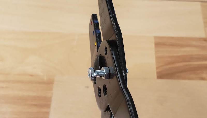
I had to shorten some screws and Spencer showed me a cool trick. Wire stripper multitools sometimes have holes in the heads labeled with common screw sizes. These are for threading in screws to shear them off. They didn’t come out perfect but it’s faster and safer than cutting them down with a cut off wheel or grinder. I used the bench grinder to clean up the threads a bit.
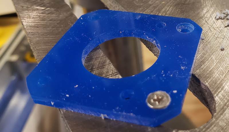
I also had to grind down the screws that held the pan mounting plate to the turn table bearing so they didn’t conflict with the mounting screws for the V-wheels. You have to be careful when you screw them in to line up the ground down side with the cutout but it wasn’t very hard. It’s faster and better looking than moving those screws slightly off center on the plate.
![]()
Gluing
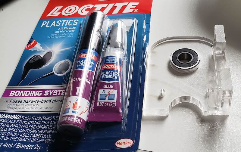
I hadn’t thought about the fact that gluing acrylic can be kind of a pain. I did a bit of research and found loctite for plastics. I did a test part the day before going into the lab and that came out fine.
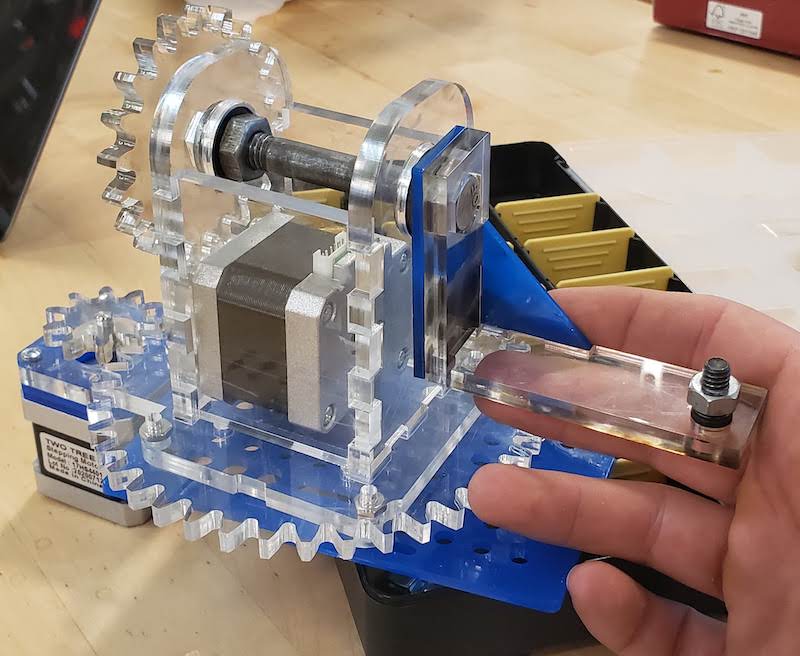
With that glue in hand I returned to the lab and glued up the tilt mount and tilt arm. Xiaolin had also 3d printed the camera mount and that fit right on.
Testing
At this point I had a working Pan/Tilt Stage that I could operate by hand. It just needed the electronics and a bit of code added in. It also needs to be mounted to the linear stage but those parts are all lost in the mail so that’s not happening yet.
Manual Operation:
I helped Jonathan get the electronics wired up to get a single motor moving and we connected that to the rotation stage and off it went.
Software
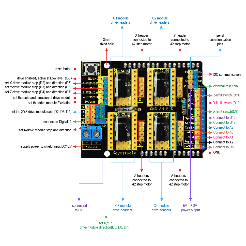
I stepped in to help Jonathan with the software when his computer died the day before the project was due. I had helped point him in the right direction earlier mostly by finding this image with the pinout for the CNC shield. This told us that we plugged in the X and Z motor drivers and that we needed to use pins 2,5 for X and 4,7 for Y. Also pin 8 for enabling the steppers.
Jonathan used the Arduino stepper library to get basic motion on these two axes. I tried tweaking the speed and steps of the motions but it was very jittery and wouldn’t produce smooth video. I knew just enough to get in trouble here and figured that I needed to adjust the acceleration of the motor. I searched for a different stepper motor library that could handle this. I found the FlexyStepper library which also had a handy example for use with the CNC Shield. This example had some helpful comments that I should have read earlier.
// For all driver boards, it is VERY important that you set the motor
// current before running the example.  This is typically done by adjusting
// a potentiometer on the board.  Read the driver board's documentation to
// learn how.
I still haven’t looked up how to do this current tuning because everything just worked out of the box and I foolishly assumed that the default values would be fine. (They were good enough I guess.)
// Note 1: It is assumed that you are using a stepper motor with a
// 1.8 degree step angle (which is 200 steps/revolution). This is the
// most common type of stepper.
//
According to the datasheet our motors are 1.8 degree per step so this is correct although running 200 steps didn’t seem to be a full revolution. Oh well, it moves and I’m short on time. Close enough.
// Note 2: It is also assumed that your stepper driver board is
// configured for 1x microstepping.
//
// It is OK if these assumptions are not correct, your motor will just
// turn less than a full rotation when commanded to.
//
Microstepping! I’ve heard of this, I don’t really know what it is, but that could also be the key to smoothing out the motion. More on this later. I don’t know what microstepping value the shield is configured to out of the box but 1x is probably a reasonable assumption.
// Note 3: This example uses "relative" motions.  This means that each
// command will move the number of steps given, starting from it's
// current position.
I assume this means relative position as opposed to absolute position which is good because we didn’t have time to add end stops and therefore don’t have absolute position for any axis.
I again messed around with the acceleration and speeds and it got better but still not great. That’s when I looked into the above comment about microstepping. I found these instructions on setting up the CNC shield and of course ignored all of it except the microstepping part. I should go back and read the rest when I have more time. I found that there is a set of headers under each stepper motor driver that control microstepping. How much each step is divided is based on what driver board we have. They aren’t labeled so I don’t know what they are but I saw that jumping all 3 header pairs put both listed drivers into their smallest microstep mode so I just went with that and applied 3 jumpers under both drivers. This worked great. The motion was immediately slower and silky smooth. Xiaolin and I recorded a video test and called that good for now.
There is a lot that could be added to the software to have a proper interface for setting start/end points and times for each axis to move or going so far as to set keyframes and interpolate between them. But I only had about 2 hours to get something working and record a video so this is as far as I could get on short notice.
Laser Cutter Quirks Addendum
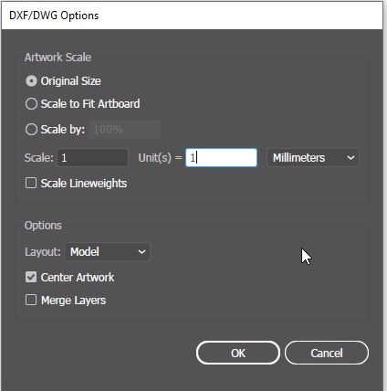
AI Units Importing DXF Files
When opening a DXF file that has been exported from Fusion it was referenced in mm. When Adobe Illustrator asks what to do about units set the scale to 1 unit = 1 Millimeters.
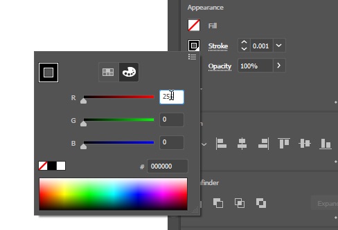
Stroke Width and Color
You need to select all the vectors and change the stroke width to 0.001 inches and change the color to Red. In the job control software the default cut line has to be that thin and red tells it to cut rather than engrave.
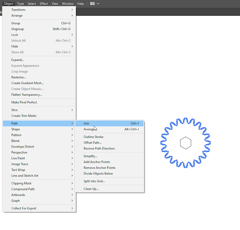
Combine Vectors
The gear generator doesn’t export a single connected vector. Select the entire gear and from the menu select Object > Path > Join.
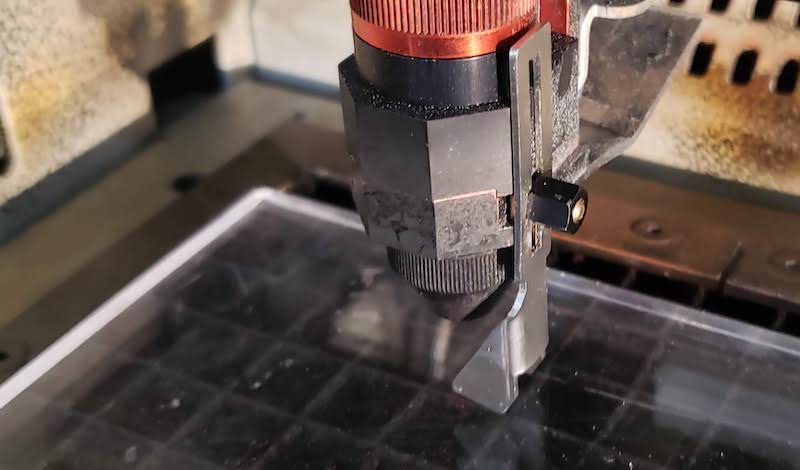
Don’t Trust the Auto Focus
My first cut didn’t come out right. Spencer suggested that it might be out of focus and showed me how to manually focus this laser. You hang the clip off the side of the laser emitter and raise the bed until the material knocks the clip off the side.