Embedded Programming
The goal this week is to get my own code onto a microcontroller board that I have designed. I have done this before with off the shelf Arduino development boards of various flavors. Last week I used the Arduino IDE to program my attiny412 board which would have satisfied most of the requirements for this week but I wanted to challenge myself and design another board using the samd11 processor and figure out how to use a JTAG programmer to get code onto it. The one trick is that I don’t have a JTAG programmer so that might be easier said than done.
ATtiny412 UPDI Programming
I setup the Arduino IDE to program my Attiny412 board from electronics design week. See that process here.
SAMD11 JATG Programming
OpenOCD on RaspberryPi
I wanted to start by programming the SAMD11 board I made during electronics production week. I don’t have a JTAG programmer but I found a tutorial from Adafruit to use a RaspberryPi running OpenOCD.
Installation
I ran this on a RaspberryPi Model B running the latest RaspberryPiOS
install dependancies
sudo apt-get install git autoconf libtool make pkg-config libusb-1.0-0 libusb-1.0-0-dev
clone OpenOCD
git clone http://openocd.zylin.com/openocd
enter OpenOCD directory and run bootstrapper
cd openocd
./bootstrap
configure native gpio twiddling
./configure --enable-sysfsgpio --enable-bcm2835gpio
run make
make
wait… for a long time. This took about 30 mins on my original RaspberryPi.
install it
sudo make install
Configuration and Wiring
Look at the list of available interfaces in /usr/local/share/openocd/scripts/interface
I’m using raspberrypi-native.cfg for my RaspberryPi 1.
Use the pinout command to get a cool visual representation of the GPIO header to know where to plug in based on the pins in the config file.
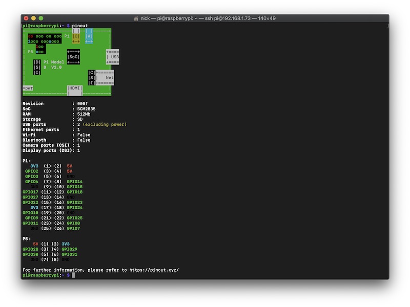
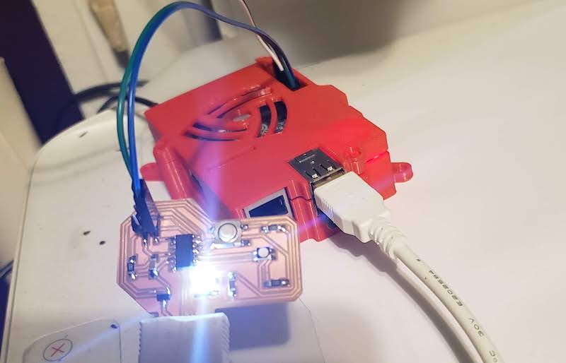
This page clarified that I can program the SAMD11C14 with the Serial Wire Debug SWD interface which is what this board from Quentin is setup for. It just needs Ground, 3.3V power, Clock, and Data which is the 4 pin header at the center of the board. The critical section in the OpenOCD config file is:
# Each of the SWD lines need a gpio number set: swclk swdio
# Header pin numbers: 23 22
bcm2835gpio_swd_nums 11 25

# If you define trst or srst, use appropriate reset_config
# Header pin numbers: TRST - 26, SRST - 18
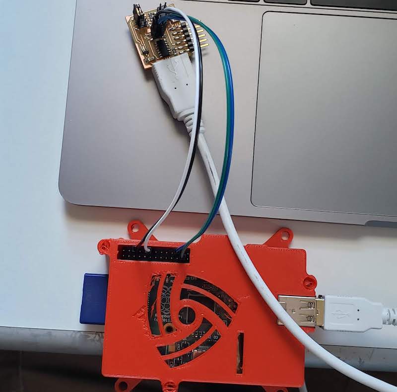
The clock signal is on gpio11 and the data signal is on gpio25. I’m not sure if I need the reset pin which is on gpio18. Those pins are connected to the corresponding pin on the JTAG SWD header on the board and the USB port is plugged in for power.
Create an openocd.cfg file for programming. The Adafruit tutorial example is for a slightly different board. This link was helpful in confirming what board target file to use. Look in /usr/local/share/openocd/scripts/targets to find config files for all the different boards. The correct one for SAMD11C14 is at91samdXX.cfg
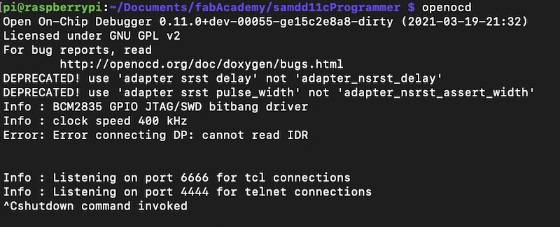
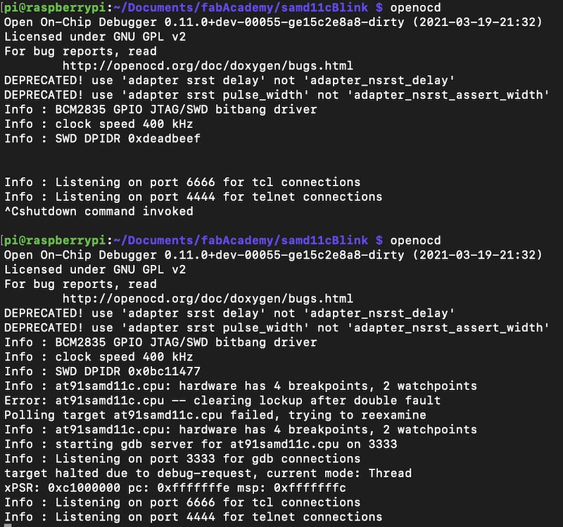
Try to connect once the board is correct. First try failed to connect. Gave a deprecation error about a few lines in the config and the error “Error: Error connecting DP: cannot read IDR”
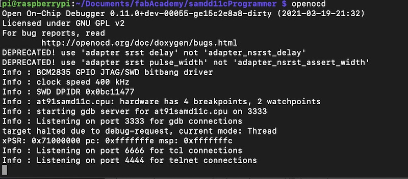
I had read that the reset pin might not be needed so I disconnected it from the board and it looks to be connecting correctly. The line “Target halted due to debug-request” is the key to indicate a good connection.
Programming
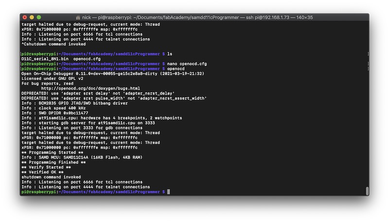
I downloaded Quinten’s bin file and added a line to program that file and verify it onto my board. Success programming and verified ok! Now I need to make a board that has some more useful outputs to have some fun with rather than just programming other boards.
I think testing this board to program my ATtiny412 board would be a bit complicated so I decided to try to run the example serial echo code from lecture. To start I wanted to use the Arduino IDE to install the tool chain. My initial attempt to compile Neil’s code linked above resulted in an error that Serial2 is undefined.
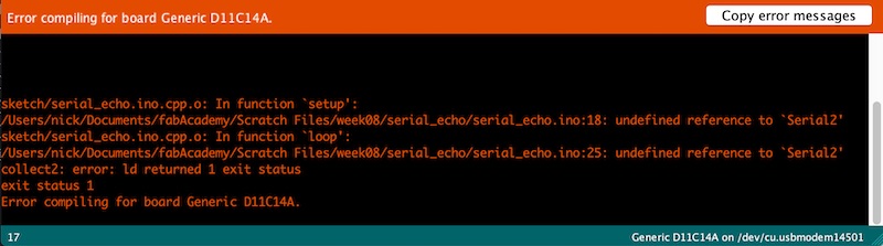
Reading through the serial section of the ArduinoCore-samd docs and it says to just use Serial for USB serial and Serial1 and Serial2 should be UARTs. It also says you need to add
while (!Serial);
to the setup function to wait for the serial connection for the Arduino serial monitor. I rewrote the echo code for these updates.
void setup() {
   Serial.begin(115200);
   //Serial2.begin(115200);
   while (!Serial);
   }

void loop() {
   if (Serial.available())
      Serial.println((char) Serial.read());
   }
I compiled this using the Arduino IDE and exported the compiled binary file. Copied that file to the RaspberryPi and updated the openocd.cfg file with the new binary. I ran openocd again and it reprogrammed the board.
source [find interface/raspberrypi-native.cfg]
transport select swd

set CHIPNAME at91samd11c
source [find target/at91samdXX.cfg]

# did not yet manage to make a working setup using srst
#reset_config srst_only
reset_config  srst_nogate

adapter_nsrst_delay 100
adapter_nsrst_assert_width 100

init
targets
reset halt
program serial_echo.ino.Generic_D11C14A.bin verify
reset
shutdown
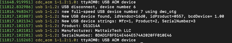
Double checking that it shows up as a USB device to the Pi I ran dmesg and saw it connect as /dev/ttyAMC0.
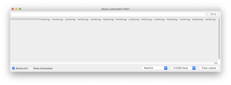
To talk to it on the Pi i tried to install minicom. That resulted in no connection. I assume it’s a minicom configuration problem. I decided to just unplug from the Pi and plug into my laptop. From there I opened the Arduino IDE serial monitor and whatever I typed was echoed back to me. I was fairly certain that this was working but because the code doesn’t modify the echo at all I wanted to be sure. I added another serial print line, recompiled and reprogrammed. It took a few tries to get the serial output right. It was definitely changing but I was getting a lot of blank lines and question marks. After a few variations I was getting responses that contained the string “echoing: " that I had put into a Serial.print statement.
New Board
Design
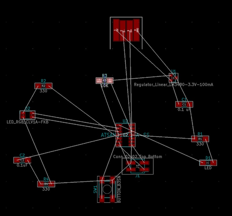
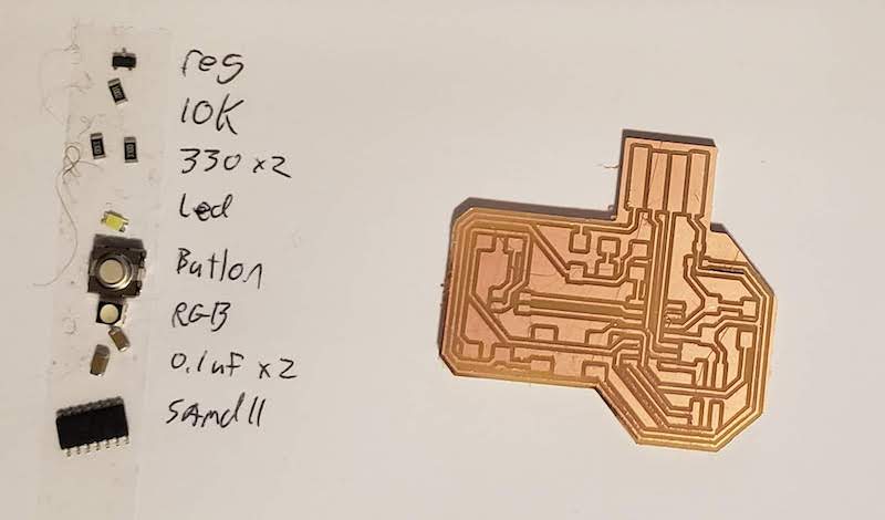
Designed another samd11 board that had something to interact with. Button, LED, RGBLED. In order to layout the board I had to dig into the datasheet for the samd11c14. There was no easy pinout diagram for this chip. In the data sheet there were a few charts and in the Arduino library there was an ascii art diagram.
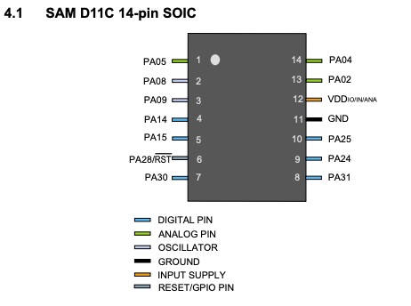
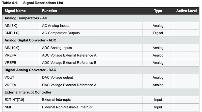
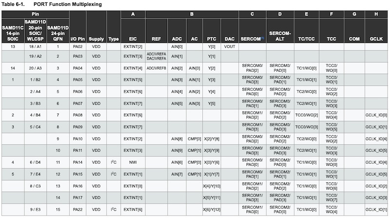
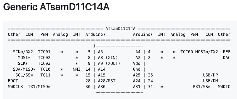
I used all of these resources and the board layout from the programmer board I had previously made to figure out which pins to attach the LEDs, button, power, ground, programming pins, USB data pins.
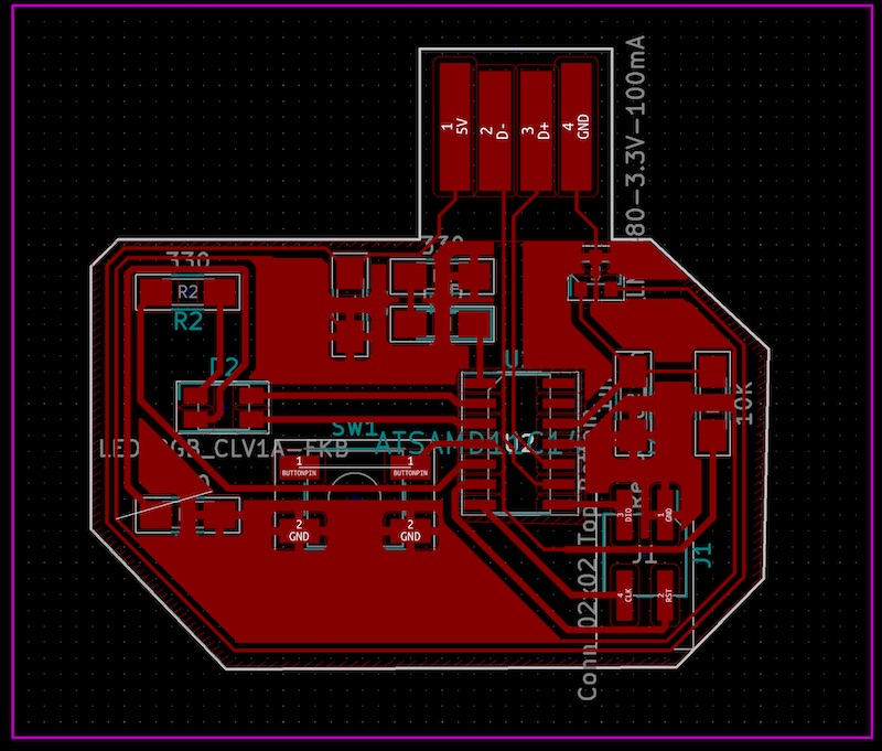
Once I got all the pins sorted out I had a bit of a fight to get the components laid out. This was the first board that I did the layout without following a tutorial. It was hard.
I also set myself up with a few challenges with the board edge USB connector which prevents me from running traces all the way around the board. Also the sot23 3.3V regulator had too small of a space under it for a 0.4mm trace to pass under it. I knew from Quinten’s board that he passed a track under it. I set the track size down to 0.2mm and I could fit one under the regulator.

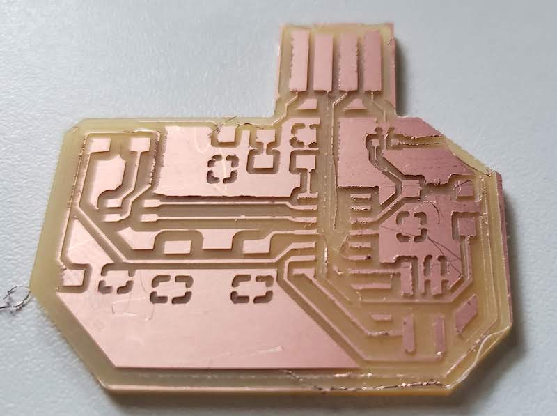
I figured since that size worked on his board I could just leave that as long as the clearance stayed at 0.4mm since that’s the end mill size I’m milling with. However once I had the finished board that had half 0.4mm tracks and half 0.2mm tracks. The track under the regulator came out fine but the longer thin tracks lifted from the board.
Milling and Populating
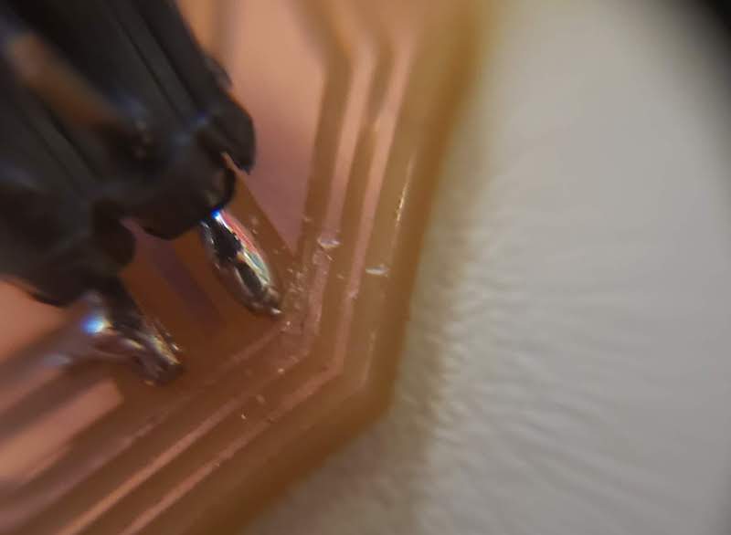
Failed Milling look at the bottom right corner.
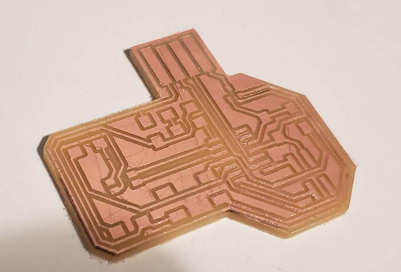
I reworked the layout to only have the thin track under the regulator and it milled fine.
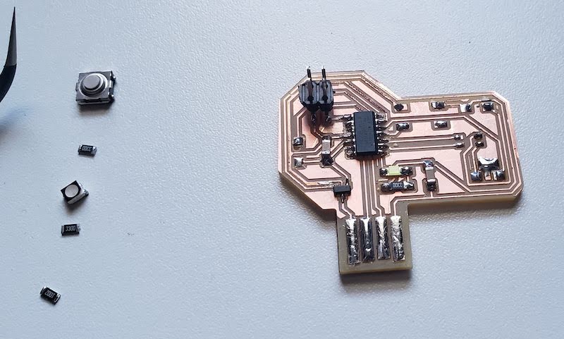
I populated the board.
When I first tried to program the populated board it wasn’t connecting. I beeped it out with a multimeter and found that there was a trace on the reset pin of the JTAG SWD header that was shorted to ground. I used an exacto blade to scrape that trace away.
Programming Down the Rabbit Hole
OpenOCD would now connect to the board.
I modified the stock Arduino Blink example to just blink a single LED and set the pin to 5 which is where I had installed a single white LED. I then ran down a huge rabbit hole of programming errors that I later concluded was something wrong with the chip, maybe because of that initial short. Initially the programming command threw an error that it couldn’t erase a sector of the flash. It wasn’t always the same sector but it always had this error.
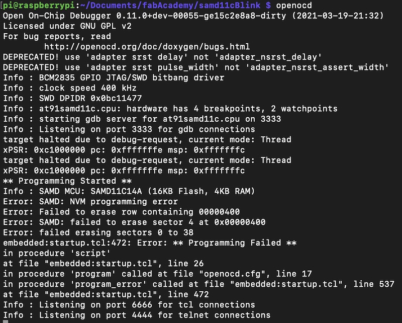
I dug into openOCD commands a bit http://openocd.org/doc/html/Flash-Commands.html I tried to do some manual flash commands. Read the sectors, they seemed ok, write protection was off. Manual erase still failed. Saw a suggestion https://www.avrfreaks.net/forum/samd51-and-openocd to use flash write_image instead of program. Found in the above doc to use flash verify_image as well. That worked. White LED Blinks.
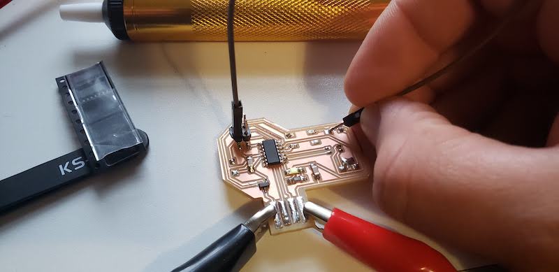
Next I made different blink versions for each pin on the RGB LED 15, 8, 9. But even with these updated programming commands it was still throwing all sorts of errors. I used a multimeter to see that when I programmed it to blink pin 15 which should have been the red component of the RGB LED that I could see the voltage turning on and off but the LED didn’t blink. I also tried to program the chip on the programmer board even though it didn’t have any LEDs on it. I could use the multimeter to see the pin turning on and off and there were no programming errors on this board. I thought maybe that the board is causing some problem so I started to depopulate the board to see if I could get just the chip and power system to receive code. I removed the RGB LED and the button. I left the white LED and resistor because I had seen them working.
I did a few more programming experiments with most of the components removed and it still failed most of the time so I replaced the microcontroller. With a new chip programming worked but didn’t blink the LED as expected. I reviewed the traces for the LED and found that I had routed the ground between the LED resistor and the USB ground through the button which was removed form the board. Jumped it with a wire and then the LED Blinked.
Soldered the button back on and that fixed it. Put the RGB LED and resistor back on and tried to flash with new software that should flash the green element. Pin seemed to work on a multimeter but LED didn’t light. At least programming still worked. Flashed it back to single LED and that still worked. At this point I think there was definitely a problem with my first microcontroller which lead me down a programming rabbit hole, and there is something wrong with my RGB LED circuit design that’s stopping it from lighting up. I also over complicated the button circuit because I hadn’t read enough of the data sheet or the Arduino library docs to see that the pins had internal pull up resistors so I included an external one and I think I did something wrong there. More experimentation needed.
A note from the future: I figured out a few weeks later that I reversed anode and cathode in my head and the RGB LED is hooked up backwards. The common lead should be connected to power and not ground. Check out my Output Devices week to see details.