Shop Bot Operation
Previous Experience
I have had project ideas for large format CNC routers for a long time but I’ve never had access to a 4’x8’ machine. I’ve done a few small sign projects on smaller machines so I’ve used vCarve for basic operations before but I’ve never made any large or interlocking parts.
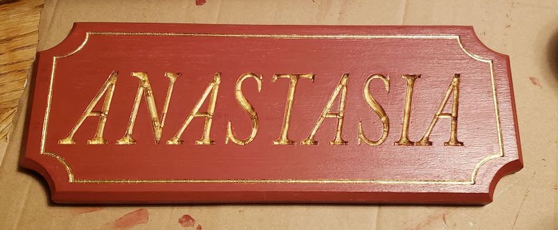
This is a replica of a sign that my grandfather carved. I did the design work for this in inkscape and cam in vCarve.
vCarve CAM
Project Setup
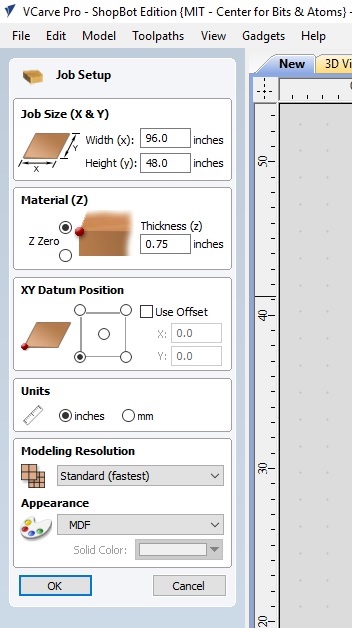
We will use vCarve to generate tool paths from DXF files. When starting vCarve create a new project. Set the job size. Spencer suggested setting this to the size of the entire bed so that you never get lost wondering where the origin is. Set the material thickness. This is really just for the simulation and for the warnings that the cut will go all the way through the workpiece. Set that XY Datum Position, this is which corner of the workpiece is the origin. Spencer suggested for our machine to use the bottom left corner as thats the closest corner to the workstation. Choose your project units inches or mm. One important note that when you change units on this screen it doesn’t convert the values on the screen from one unit to the other but if you come back to these settings later it does convert them. The Modeling Resolution and appearance only affect the on screen preview.
Import Vectors
Next you import vector graphics. vCarve can’t read SVG files so use DXF. One important thing to keep in mind is that DXF files don’t know anything about units. So if you export in mm from your design software make sure that vCarve is set to mm to import or your vectors will be off by a factor of 25.4. It is fairly obvious because that’s a very large scale factor to be off by.
Another thing I like to do is immediately after importing I group vectors so that pockets or other interior geometry stays locked to the outline it belongs with. You have to ungroup again to cut but it makes nesting much easier than having to do a selection box and hoping you got all the internal parts every time you want to move things.
Close Vectors
Next step is confirming that all the vectors are closed. Click on the Join Open Vectors tool and select all the geometry and there will be a counter showing a count of open vs closed vectors. Importing from Fusion 360 I’ve had no problems with open vectors but it’s worth checking. There are tools to close vectors in that menu if needed.
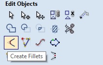
Add Fillets
Next you need to add fillets if you have any geometry that needs sharp corners because a round bit cannot cut a square sharp corner. I chose to use T-bones for nearly all my tab and slot joints because I wanted to maximize the contact surface on the short side of the slot. Using a Dog bone would have removed some surface area from both the long side and the short side. I also chose to add some normal fillets to the external corners to remove the sharp corners. This could have been done in the design files. A few notes on the fillet tool in vCarve. It asks for the radius of the tool rather than the diameter of the tool so make sure to divide your to tool size by 2. Also if you change the units of your job it will not convert this value.
Create Tool Paths
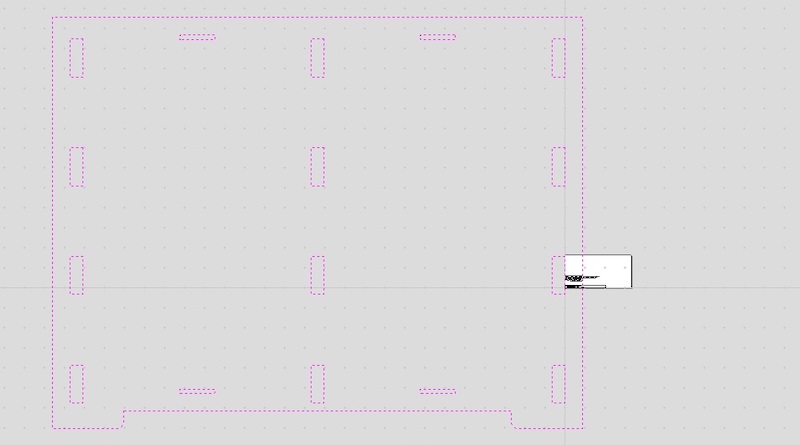
Once the vectors are ready for cutting create tool paths by selecting all the vectors that will use the same cut settings and choose the appropriate tool path type. For this project I used Profile cuts to outlines and large holes. I used Pockets for the holes that tabs will fit into and the slots for the straps.
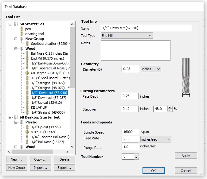
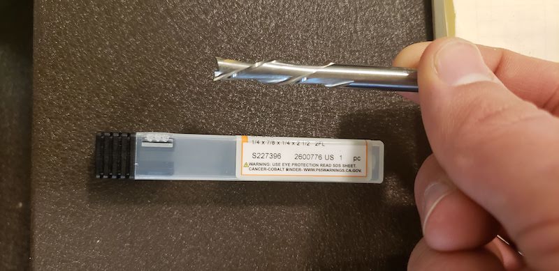
Regardless of the tool path type you need to set the Start Depth and the Cut Depth. Importantly, the cut depth is referenced from the start depth not from Z zero. Next select the tool for the cut. At our lab since the tool library is on a shared computer that anyone can change you should always double check the tool settings. For most of my cuts I used a 1/4" down cutting end mill using these settings suggested by Spencer. Pass Depth is usually the same as the tool diameter so 1/4" in this example. Step over, 48%. Spindle Speed 16000 RPM. Feed Rate 2.5 inches/second. Plunge rate 1 inch/second. Tool number doesn’t really matter for our machine because we don’t have a tool changer but it must be unique for each tool you use if you are going to export multiple tool paths in a single file. Once the tool is selected confirm that the number of passes is automatically calculated as you expect. I’m using 3/4 inch plywood and my 1/4 inch tool has a 1/4 inch depth of cut so it calculates to 3 passes.
Pocket Tool Paths
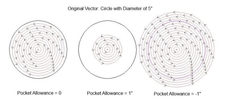
Pocket tool path settings include choosing the clearance method Offset or Raster and the cut direction Climb or Conventional. I stuck with the defaults. For the pockets on my design that received tabs for assembly I used the pocket allowance setting. Adding a negative value increases the size of the pocket and a positive value with decrease the size of the pocket.
Give your tool path a good human readable name and click Calculate.
Profile Tool Path
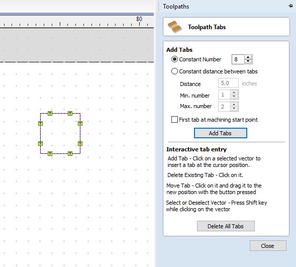
Profile tool paths start by selecting if the tool should cut outside the line, inside the line, or on the line. I used all three for different tools. I cut outside profiles of my parts outside the line. I cut inside the line for the large holes in parts. I cut on the line with a V bit to chamfer the edges of some of the parts. You can also set Climb or Conventional direction and add an offset. To prevent parts from breaking loose on the machine check the box to Add Tabs. Set the length and thickness of the tabs and then click Edit Tabs. I kept the default 1/4 inch length and depth. Under the edit tabs I chose to do a fixed number of tabs for each part. 4 tabs for smaller parts and 8 tabs for larger parts. I manually dragged them around so that they were approximately evenly distributed and on surfaces that would be easier to remove them and less visible on the assembled part. Once the tabs are in place click close.
There are a number of advanced profile options which I didn’t use. Then give the tool path a good name and click Calculate.
Preview Tool Paths
Once the tool path has been calculated you can display a 3d preview on your work piece. This is a good time to check that parts will cut all the way through and that the tabs are in places that will hold parts down. I had a few parts that ended up too close to each other so that I couldn’t put tabs between them. I just moved the tabs to adjacent faces and it worked out fine. From this point you can double click on a tool path to edit it and recalculate. If the preview is ready to go you can export it to the shopbot controller.
Setting Up The Shop Bot
Overview
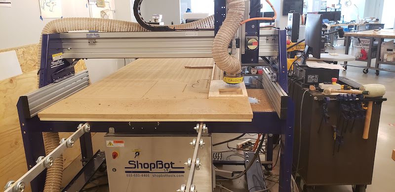
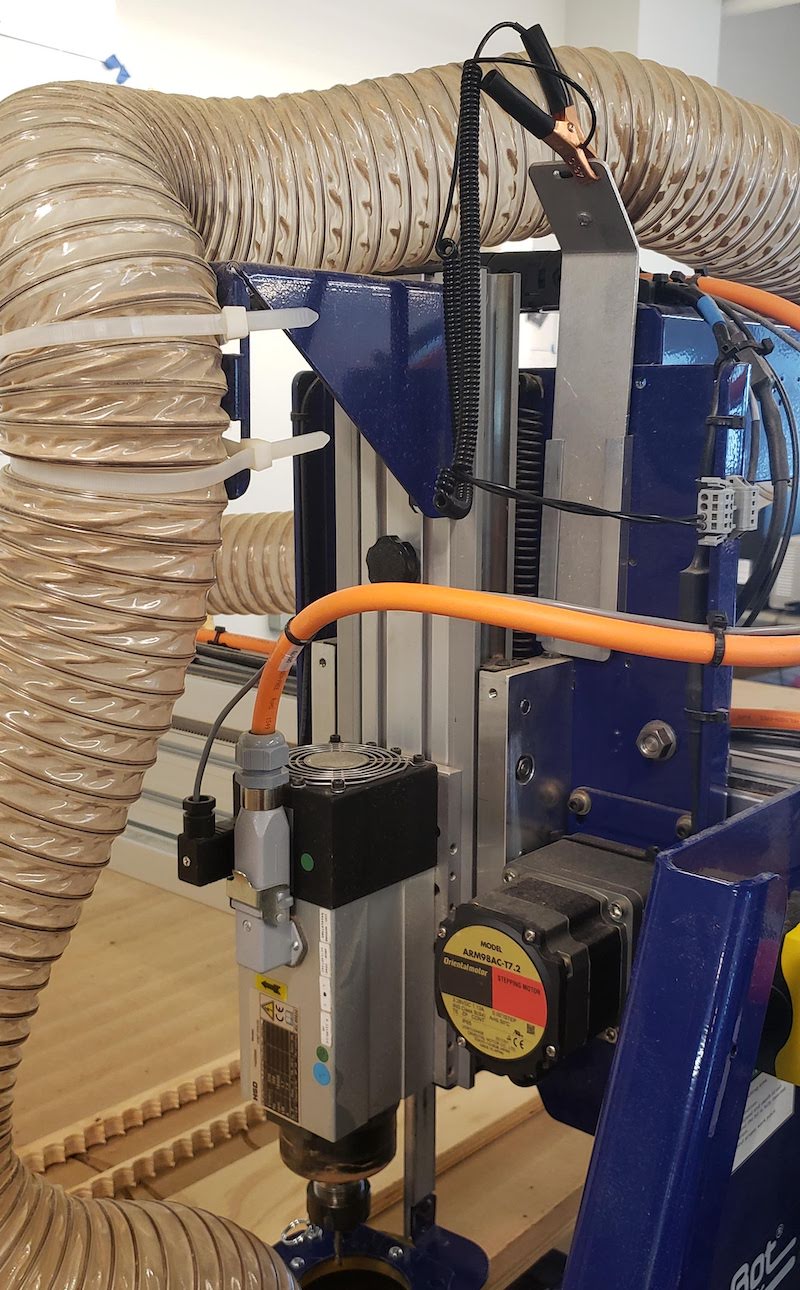
Machine Overview:
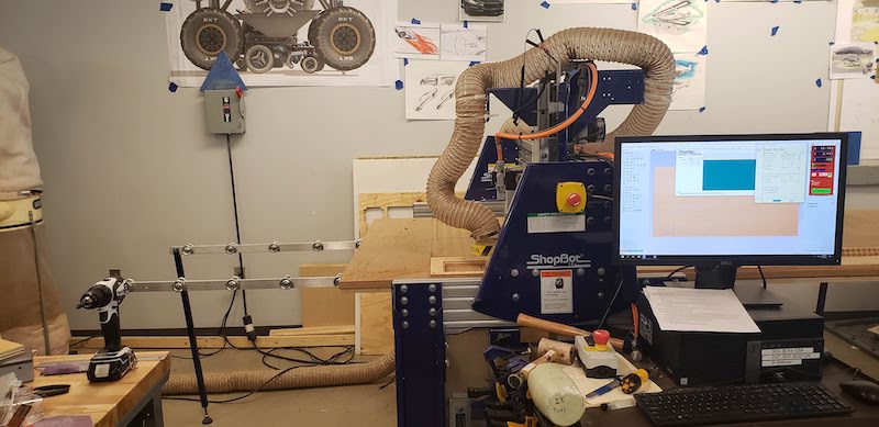
Workstation Overview:
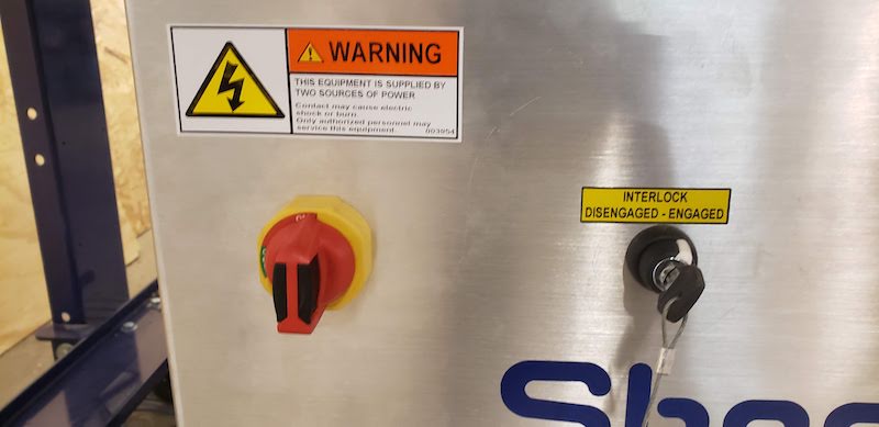
First turn on the Power switch located below the bed. The spindle lockout is controlled by the key switch. The wrench to remove the collet is attached to the key so that the spindle must be disabled in order to remove the tool from the spindle.
Spindle Warmup
The first time you turn on the machine for the day run the spindle warm up routine. Make sure the collet and tool are tight and not interfering with anything bbefore powering the spindle. Click on Cuts -> C5 - Spindle Warmup Routine. This takes about 10 minutes.
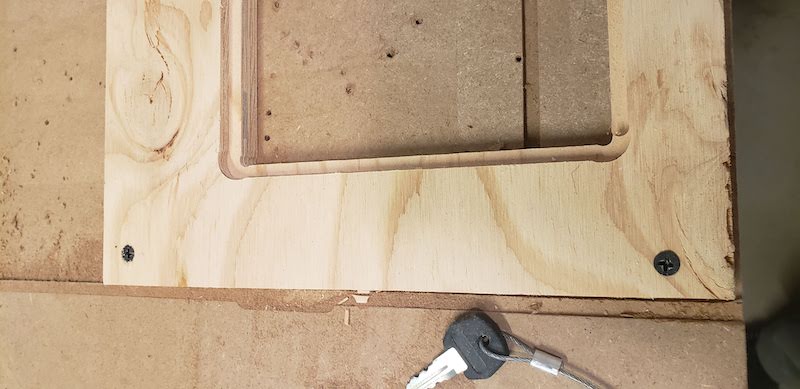
Secure Work Piece
Next secure your workpiece to the spoil board. We use drywall screws to secure the workpiece down. Make sure the piece is as flat as possible on the bed. Make sure that your cuts avoid the screws. We usually secure work at the front left corner of the bed when standing at the workstation.
Install Tooling
To install a tool in the spindle you must first remove the dust collector. Loosen the black knob above the spindle motor to lower the dust collector nozzle. You many need to raise the z axis for the dust collector to clear the bottom of the tool.
Lift the pin on the dust collector lock to slide it off the fork.Use the splined wrench which is attached to the lock out key and an open end wrench to loosen the collet. If there is a tool installed remove it so it doesn’t fall out.
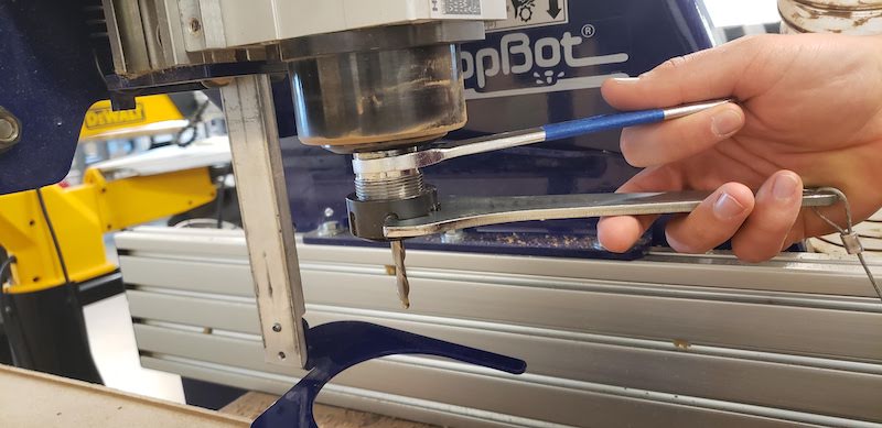
Then remove the collet holder and the collet.
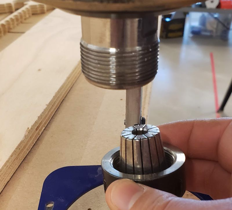
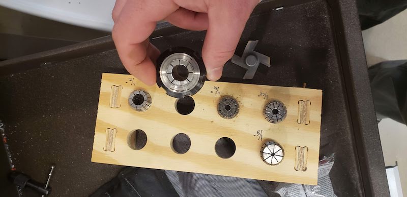
If your next tool uses a different sized collet from the one currently installed there are more sizes in the workstation drawers.
Reinstall the collet if it was removed. Install the tool checking if there is an insertion depth mark on the shank. If not make sure to not to clamp any of the geometry of the cutter into the collet. Use the two wrenches to tighten the tool. Reinstall the dust collector and slide it to an appropriate height based on the depth of cuts you will be making with this tool. then tighten the black knob to hold it in place. Install the key into the spindle lockout as it is ready for cutting.
Zeroing
Drive the machine to the corresponding corner of your work to what you had setup in vCarve. Usually the front left corner for this machine setup. Eyeball the X and Y axis by jogging the machine with the keypad which is accessed by the yellow keypad icon or the ‘k’ key on your keyboard. Be patient with the jog controls because I did manage to crash the software by tapping the arrow keys to quickly several times. Once the X and Y are in place select the Zero Axis menu and check X and Y. Move to the center of your work area and then close the keypad. On the main control window there is a button for zeroing the Z axis. Click this and then remove the alligator clip and zeroing paddle from the Z axis carriage. Clip the clip to the side of the spindle. Place the paddle on your work piece under the tool. Touch the paddle to the tool and confirm that input indicator 1 on the control window turns green. Then Zero the Z axis.
Cutting
Safety Notes:
Before starting the machine make sure you are not the only person in the lab. Make sure everyone in the vicinity of the machine has eye and ear protection. Start the dust collector before you start the spindle.
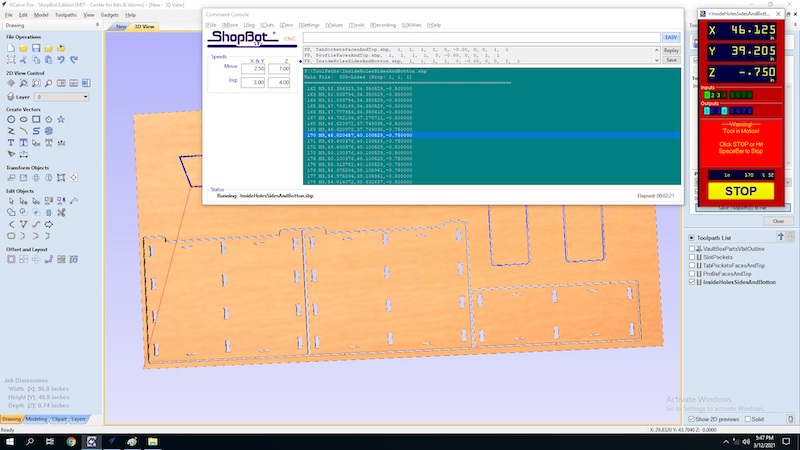
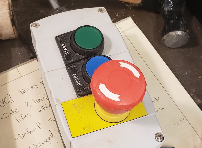
Once the machine is set up and your tool path is ready load the tool path into the shop bot software. Click the big START button. The software will pop up a number of checks that the right tool is in the spindle and that Z is zeroed. Lastly it will tel you to press the start button on the Emergency stop to start the spindle. Confirm the spindle is started and click OK. Monitor the cut. Use either the space bar to pause the cut or the Emergency Stop button if something goes wrong. Listen to the sound of the cut. A change in the sound is a good indication that something isn’t quite right.
Make sure you order your cuts so that pockets and internal geometry is cut first so things have less of a chance of moving. When one tool path finishes change the tool if needed and load the next tool path.
Testing The Machine
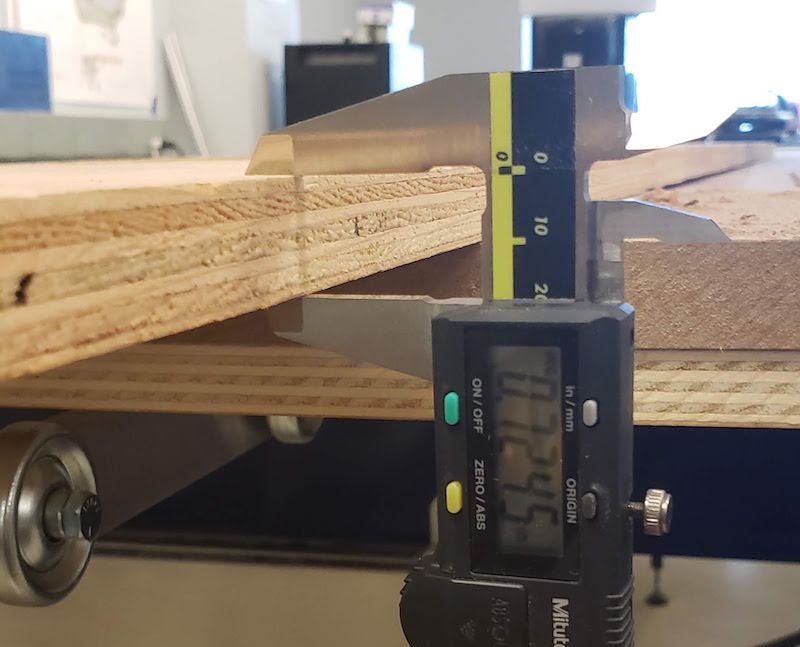
I tested the runout with a simple test square. I drew a 5"x5" square in vCarve and cut it out with a 1/4" down cutting end mill. I measured the width of the cut to check the runout of the spindle.
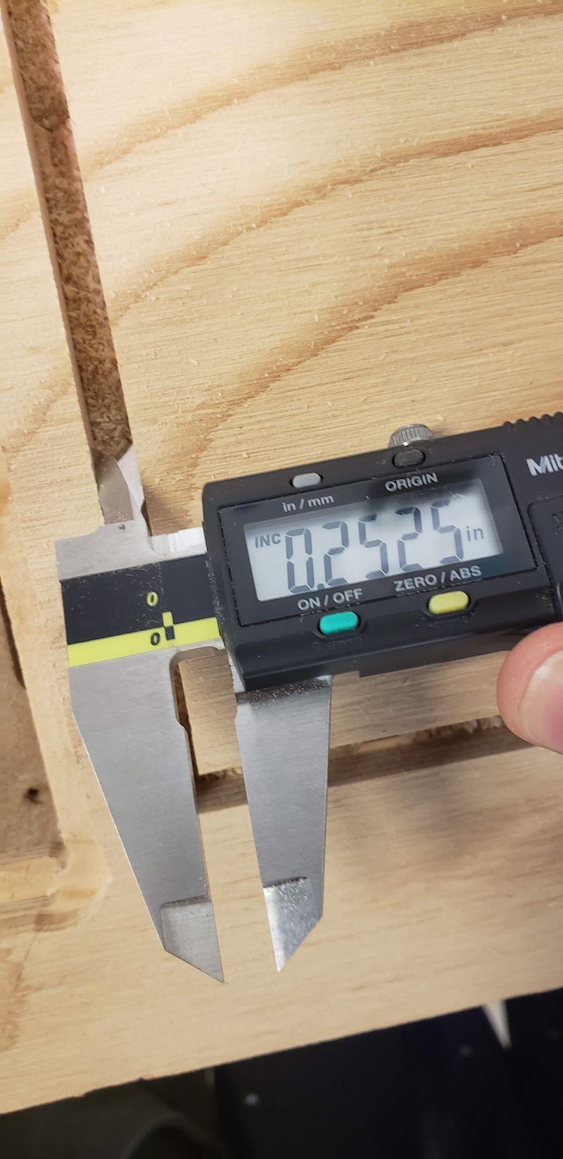
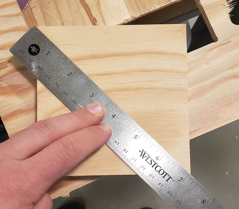
The cut measured 0.2525". (ActualCut - ToolDiameter)/2 = runout (0.2525 - 0.25)/2 = 0.00125" runout. I also tested the alignment of the machine by measuring the diagonal of the square and it was 7 1/16" on both diagonals so it cuts square at least on a small scale.
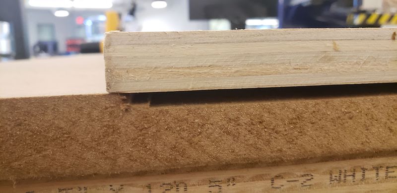
I also noted that this cut was not set quite deep enough. I had set the cut to 0.74" because the 0.75" plywood is slightly undersized.
I noticed a potential problem while executing these cuts. When the machine would make a plunge cut there was significant deflection of the workpiece as well as the entire machine bed. This will show up again later.
My Project
Inspiration
I’ve had my build something big project in my head for a while. One of my jobs is as a parkour coach and we often bring equipment to teach classes in schools. Frequently the schools we teach in don’t have a lot of space for us to store this equipment between classes. One of the most useful pieces of equipment we use is a vault box. Unfortunately they are quite large. I built one last summer using 2x4 framing and plywood and it’s quite heavy and hard to move.
I wanted to use tab and slot construction to build a box that could be assembled and then packed flat for storage or transportation. I also had the idea to use ratchet straps to hold the box together when it is assembled so it wouldn’t need traditional fasteners.
I have done plenty of research to find what else is available for vault box designs. I don’t know of anything that has solved this problem in this way. Traditional framed box plans. CNC cut boxes with traditional fasteners. A different shaped CNC cut box with traditional fasteners
Design
I designed my box in Fusion 360. I knew I was going to want to create multiple sizes of this box so I created a highly parameterized design. The base of the design is a trapezoid specified by the length of the top and the height of the box. The angle of the sides of the box I copied from the first design posted above at 18.8 degrees. I added tabs in orientations so that the sides, to p, and bottom could all be added or removed without interfering with each other. I extruded by the material thickness parameter.
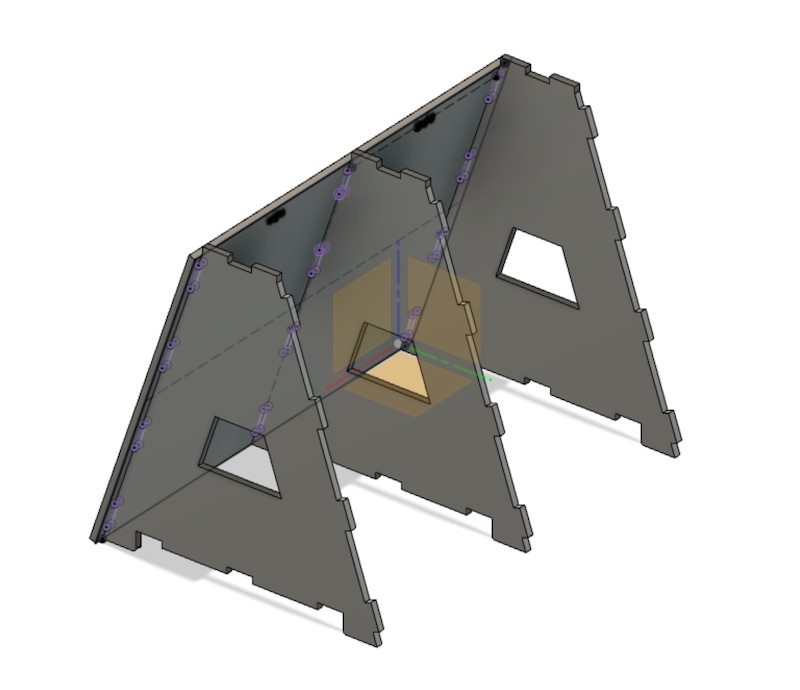
Once I had one side modeled I copied it twice to create three ribs and created sketches on the plane where the next part would be and projected the geometry of intersecting parts to define the next part.
Once I had all the sides of the box I added slots for the straps to hold the sides, top, and bottom onto the ribs. I also realized that it had 6 legs since I just copied one end three times so I added a sketch on the middle leg and cut off the foot.
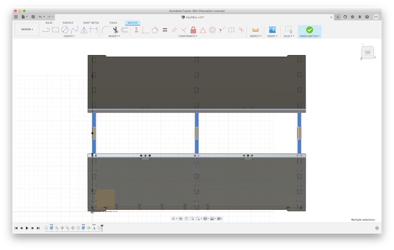
I learned from the laser cutting assignment that I can create a new sketch on the face of a body and you can export that as DXF for import into vCarve.
Once my design was complete I realized that it would not fit on a single sheet of plywood which is how much material I had for the project. I scaled it down to be 24" tall and 30" wide. I found when I modified the parameters the slots didn’t adapt properly.
I had used the mirror feature and something didn’t work about that I redrew them just as rectangles instead of mirrored lines.
Cut Testing
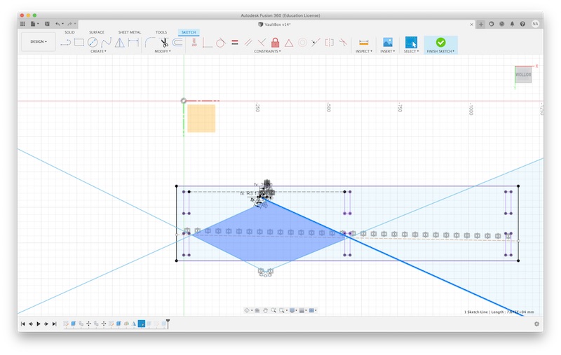
Once my design was complete I needed to do some test cuts. I foolishly didn’t start by measuring the plywood and just assumed it was .74" for some reason. I knew I needed to test my joints so I imported my files into vCarve and used the Node edit tool to cut off just the tabs and slots.
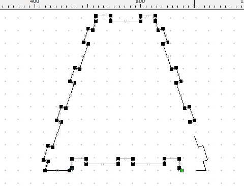
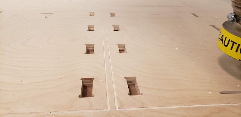
I setup a row of 4 slots and 4 tabs to test the general geometry and I would adjust from there.
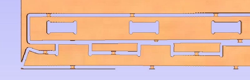
This test worked surprisingly well The fit was a bit loose on the narrow dimension but too tight on the long dimension. The parts had to be hammered together but they did fit.
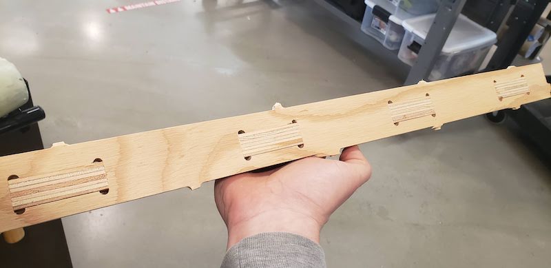
From there I remembered that I should actually measure the thickness of the plywood to get the tolerance right.
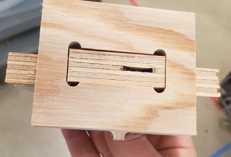
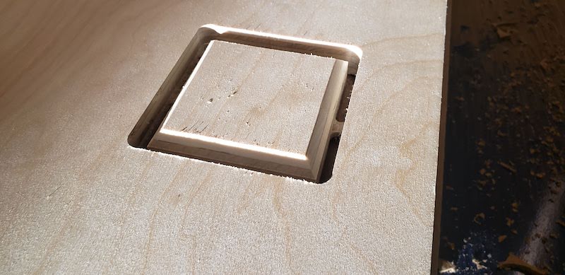
I adjusted the design in fusion, re-exported, and then used the node edit tool in vCarve to create a single tab and slot. The short side of a slot is based on material thickness and the long axis is set to be the same size as the tab so based on the results of the previous test I adapted the material thickness more accurately and decided to add an offset to the slots. I guessed that adding 0.02" would make the fit just right. I wanted the joints to be sturdy but able to slip together easily without tools and be removable also tool free.
I used the pocket allowance setting and didn’t think that adding a 0.02" offset would do it on all sides creating a 0.04" total adjustment. My first parts were a bit looser than I wanted.
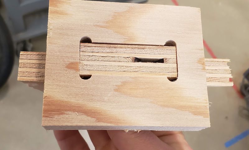
I realized my mistake and cut another pocket with a -0.01" offset and it fit very well.
Cutting
At this point I had the settings dialed in I setup the full sheet of material and had one more test to do. Installing the full sheet of plywood revealed a slight problem. The area of the spoil board that had been surfaced was exactly 96 inches long but our plywood sheet was 96.5 inches. I didn’t have enough time to fix this and get my cuts done so I just aligned my cuts to the other end of the plywood and screwed the sheet down as best I could.
I wanted to use a V bit to chamfer the edges on the top and sides of the box. We did a test in our training with a V bit and the cut it out and it didn’t cut on the line as I expected so I wanted to do a test cut. I made a square and cut with a V bit directly on the line and made a profile cut with at 1/4" downcut end mill. That came out as expected but was a bit deeper of a chamfer than I wanted.
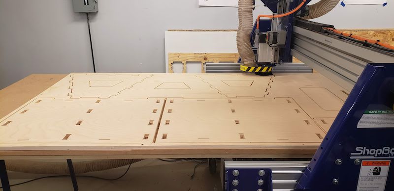
My first tool path for my final parts would be a V bit pass at 0.2" deep. I cut outlines of the two side faces of the box and the top with a profile cut using the on the line setting. This instantly revealed a problem with the flatness of the work piece. The cut was deeper than I expected on one edge and then reduced down to no cut at all on the opposite edge. Confusingly I would have expected the edges of the plywood where I had the work holding screws to be the low point and the middle with no work holding to be the high point but it was the opposite of that. The deepest cut was right where the screws were and the shallow cut was in the middle.
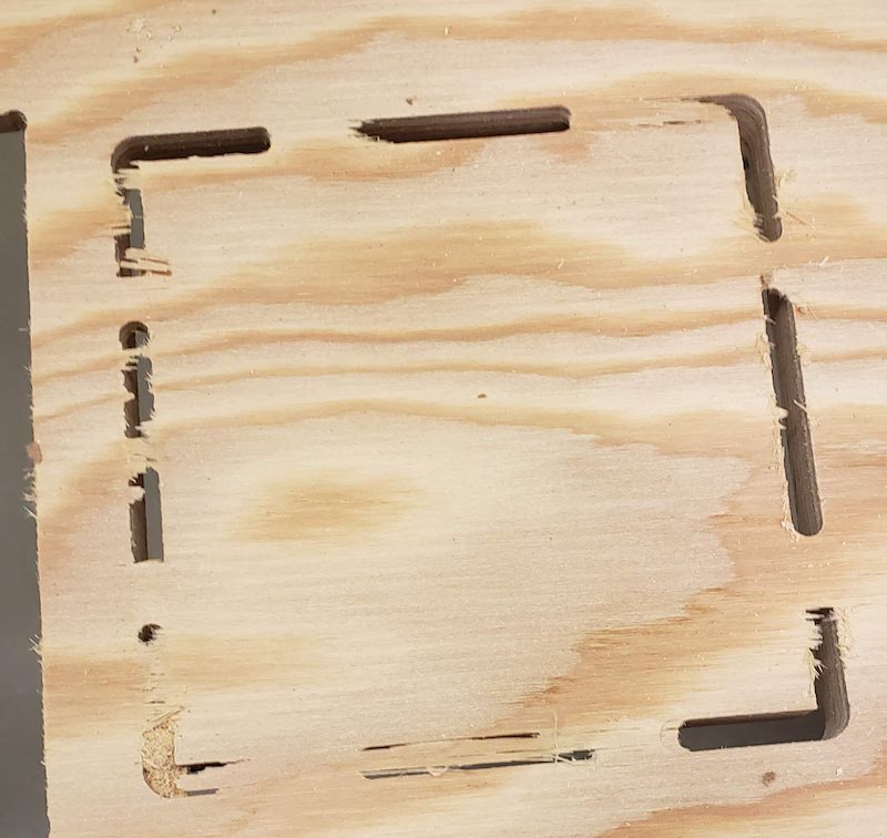
At this point I had to press on or accept that I ruined my sheet of plywood so I pressed on regardless. I made a pocket cut for the slots in each of these parts making sure to include the -0.01" offset for good fit. This was by far the longest time a cut took. It took about 25 minutes to cut 28 slots. Next I made a pocket cut for each of the slots for the straps to go through. This was just a single pass with the tool for a 1/4 inch wide slot so it was much faster. Next I made the profile cut outside the line to cut out the sides and top fo the box. I left tabs in place and had to creatively orient them because I had placed the two sides of the box so close together that there would be no material left for tabs to attach to between them. Once I saw that those had cut well I moved on to the ribs and bottom of the box. I made a profile cut using the inside the line setting for the large holes in the ribs and the bottom of the box. Then profile cuts for the slots and tabs in the bottom. I should have cut them at the same time as the others. Then I ran the outside profile cut to cut out all those parts.
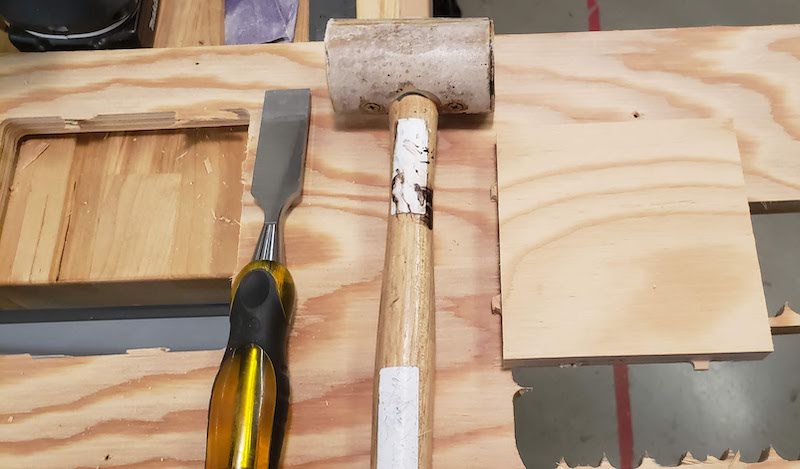
After all the parts were cut I used the chisel and hammer to cut all the tabs.
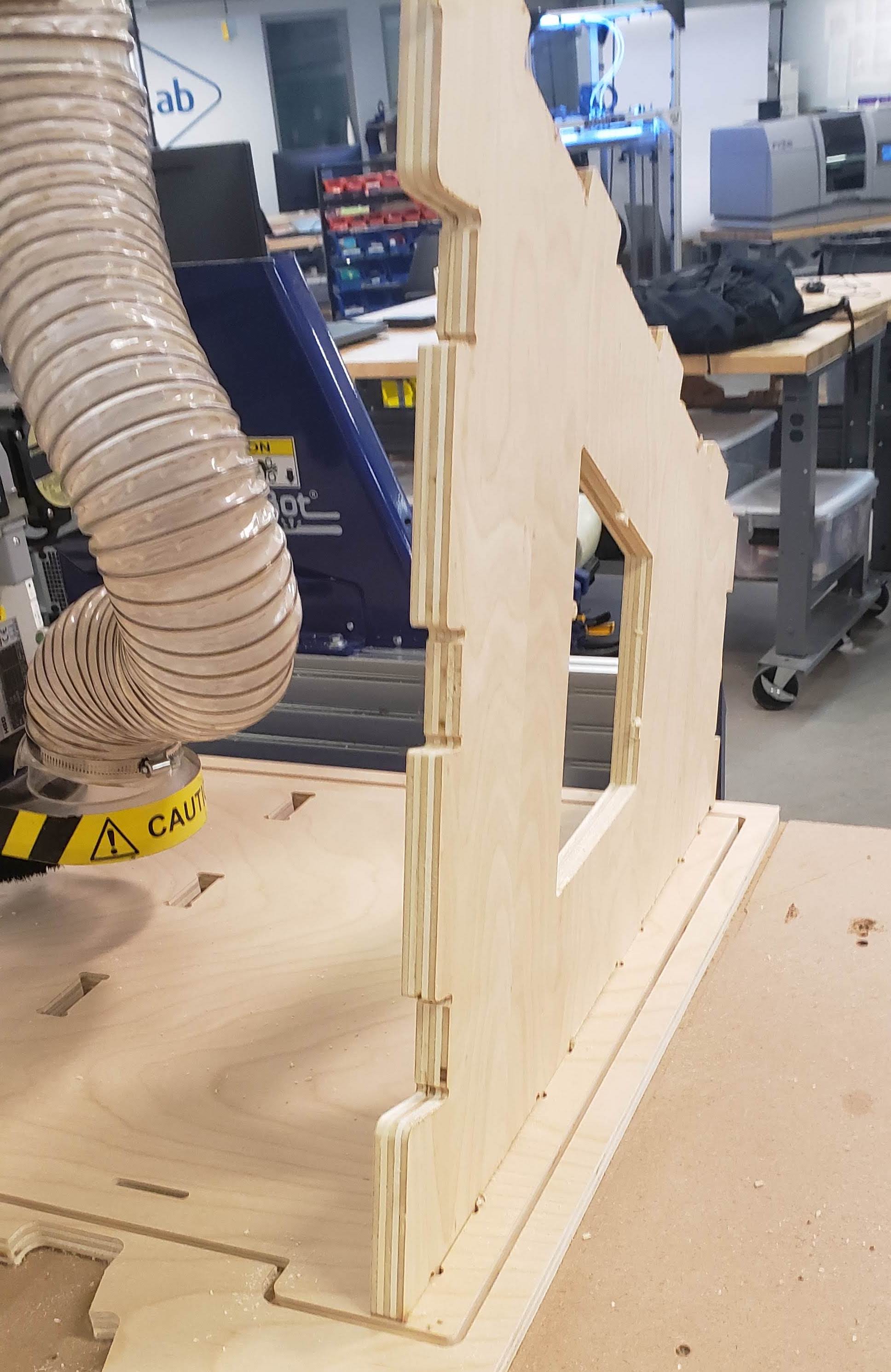
I quickly cut one of the sides and very excitedly tried to fit it into the face of the box that was still attached to the bed. It fit! I did a little happy dance and then went on with cutting tabs.
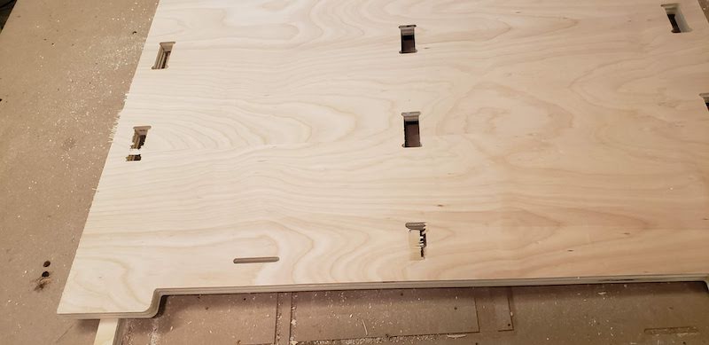
Once I got the parts off the machine I noticed that one part didn’t cut quite all the way through. This must be another side effect of the bed not being quite level. It was thin enough that I didn’t even need a tool to break it out.
Testing
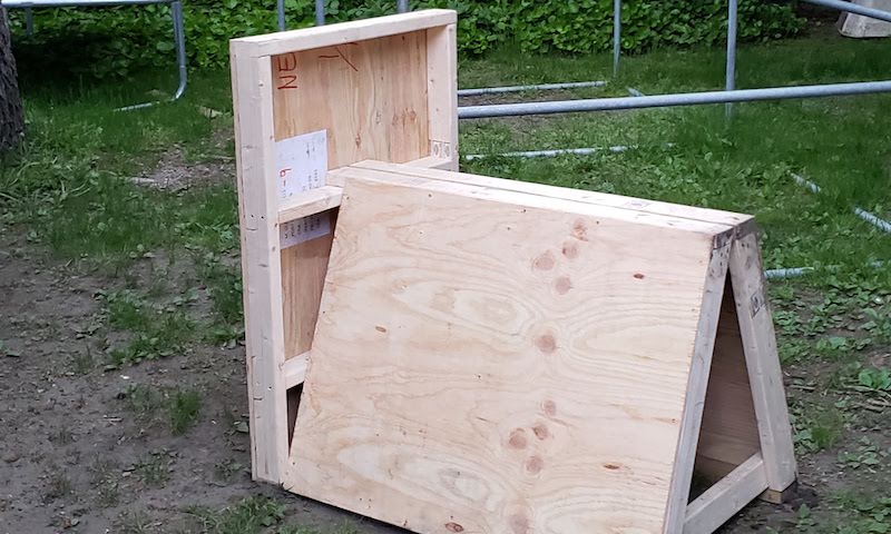
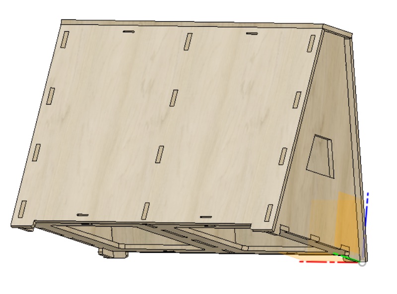
I built the box and everything just worked it was great! I did a few quick jump and vaults on it in my living room and it was all good. One of the straps I had was too short but even with only one strap it feels solid.
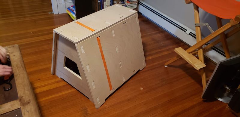
The next day I took it outside and gave it a good test. It feels rock solid.
Assembly 6x speed. Actual time ~6 minutes.
Disassembly 2x speed. Actual time ~2 minutes.
Community Response
I posted these pictures and video to a parkour equipment constructors group and the response has been overwhelmingly positive. Many positive comments have asked to buy either finished boxes or the plans so I’m going to keep refining this design into a product.
Design files
These files are scaled for a 0.75 inch material thickness and don’t have fillets that are added at CAD time. I would not recommend using these designs for parkour movements until I have throughly tested this design and which point I will post updated files for public release.
These files are licensed under the Creative Commons CC BY-NC-SA 4.0 license
Box Top
Box Bottom
Box End Rib
Box Mid Rib
Box Face