Electronics Design
I have a bit of experience designing circuits on bread boards and connecting up off the shelf microcontroller dev boards to switches, LEDs, and other input and output devices. I have never designed my own circuit boards but the theory is largely the same. Circuit boards replace the wiring in a more compact, harder to change form factor. To get started I will be designing a simple circuit with a microcontroller, a button, and an LED. The microcontroller needs a power supply and a way to program it. The button and LED need to use one of the pins on the microcontroller as a power supply and a connection to ground to complete that circuit. They also each need a resistor. The microcontroller has optional built in pull up resistors that I can use for the button, so I don’t need to add an extra component on the board. For the LED I will use Ohm’s Law to calculate the right resistor value based on the voltage of the microcontroller and the current needed by the LED.
To design this board I will be using KiCad as I’ve been hearing good things about it as an open source, fully featured circuit board design software.
KiCad
Learning The Basics
Contextual Electronics quick start This is a bit old, 2017, but got me going quickly.
Followed Kris’ high speed instructions which were clearly indented for someone who knew what they were doing, but I wanted to get the library installed and working so I had the right components and footprints.
Created his suggested dummy circuit just to place some parts and make some connections. Followed through to route traces, exported SVG, sent that through mods to generate g-code for the traces.
Schematic

Layout

Traces SVG

Mods Toolchain for svg

Again a bit slower
Another KiCad lesson from Kris at Aalto Fablab
Followed along with this to make the basic echo hello board with an attiny412. Added Button and LED.
Schematic makes sense, using labels makes things cleaner but a bit harder to read. What is the difference between a local label and a global label in kicad? Both seem to do the same thing for now. I expect it has something to do with larger projects. Got confused because the global label tool tip says something about same named things being connected and the local label tooltip didn’t say that.

Kris had a few good tricks. Use PWR_FLAG to note the sources of power in your schematics, positive and negative, so that the rules checker doesn’t complain that your power pins are not driven.

Track settings, Net Classes Tracks 0.4mm, clearance 0.4mm so that our end mills can cut them.

For layout connect comms pins and positive power pins. then use copper pour/ filled zones to fill in and connect the grounds. Use keep out areas to block the copper pour from getting in places you don’t want it. Copper Zone properties clearance 0.8mm, minimum width 0.4mm, thermal clearance and thermal spoke width 0.5mm.

Learn hot keys. Cmd + F1 is the hotkey list on mac. Shift + X is draw new trace. D is drag a component/trace/etc which maintains connections and moves things around to accommodate. M just moves the selected component and leaves connections behind.
Kris suggested using the drawing layer instead of the edge cuts layer to create the “interior” or board outline SVG. Use a margin to make some space around the board so there is an outline for it to cut and the board and traces line up.

Take advantage of changing the grid size for different operations.
I don’t understand why my copper fill has a big margin around it. This resulted in my traces SVG having a lot of extra cutting paths for nothing. I manually edited the g code to remove the extra outlines.
Traces Design File
Interior Design File
KiCad Files
Milling and Assembly

First cut I wasn’t paying enough attention in mods and I forgot to invert the traces and did’t notice until I milled the board. this resulted in a negative pcb. But it tested out my toolchain. I switched to using the CBA edition of mods because of the errors I found last week with the g-code module of community mods incorrectly representing the speed. I did have another issue with CBA mods not making multiple passes when I used the mill outline preset to cut the outline of the board so I actually used CBA mods for the traces and community mods for the outline. I’m cutting traces at 1.5mm/s or 90mm/min. For these boards that’s fast enough and I’m not worried about breaking bits. Kris mentions in the video to his students that he has some new bits that are running at 20mm/s so I want to message him to see what kind of bit that is.

Soldering the board went great. No bridges. I had some confusing on the LED to figure out which end was the anode/cathode but I found a good diagram on the item page from amazon. I did have to do some math to determine the right value for the resistor. I check the attiny412 data sheet and it will run from 1.8V-5.5V. I wanted to select a resistor that will let the LED work at any of those voltages. At 5V, to get 20mA of current on the LED I would need a 250Ω resistor. At 3.3V to get the same 20mA I would need a 165Ω resistor. I decided to use a 330Ω ressistor because it was the closest I had to 250 and would keep the LED safe at any voltage safe for the attiny.

As I added parts I did some continuity testing with a multimeter to make sure everything was connected where it was supposed to be and not connected anywhere else.

Programming and Testing
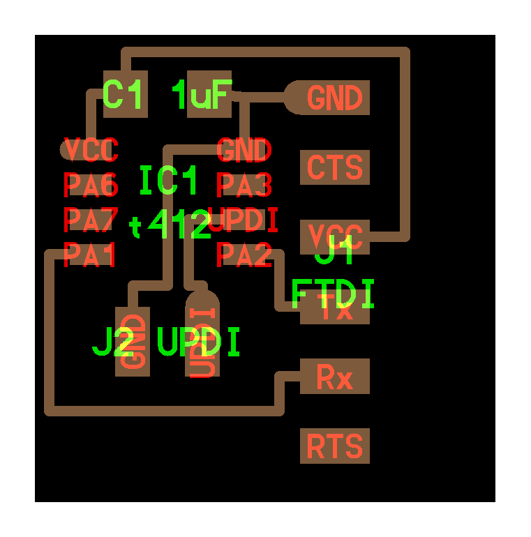
To program it I planned to use the FTDI programmer with a resistor. I was going to just use some jumper wires and solder a resistor into them but I only had SMD resistors and Neil already had published a board file for the right connectors. I figured I might as well use the tools I had available and make anther board to get some more SMD soldering practice.

Programming pointers from Adam, a fab academy instructor at Charlotte Latin School.

I initially looked at using pyupdi. My python installation on my mac is a bit messed up and I hadn’t done much in linux yet so I decided to try setting it up in my unbuntu virtual machine. I got everything installed but I ran into a permissions issue talking to the USB port. I couldn’t tell if that was a linux problem or a virtual box problem. I decided to try the arduino IDE megaTinyCore rather than continuing to fight with that. I tried in the linux VM but ran into the same permissions problem with the USB port but it was so easy to install that I repeated the process on the native macOS installation of the Arduino IDE and downloaded Neil’s hello.t412.echo.ino. To program the board with the updi adapter board and the Arduino IDE you need to choose the attiny412 for the board and the chip and set the programmer to the serial and 4.7k(pyupdi style).

I also added in a few lines to the setup function to blink the LED so that even if the serial port wasn’t working off the bat I’d have some positive indication that the programming worked. (This proved useful).

I had confirmed earlier in my design that the attiny412 works from 1.8V to 5.5V so I left my FTDI programmer in 5V mode and used it’s breakout wires to connect 5V directly to VCC on the FTDI header on my board. I connected Ground, RX, and TX to the UPDI intermediate board. Connected Ground and UPDI from the intermediate board to my board. I hit the upload button in the Arduino IDE and off it went.

Verify Successful is a good message to see when you’re in a bit over your head, and the Blue LED lit up for half a second as the program started running.

I rewired the FTDI board directly to the FTDI header on my board to check if the serial echo was working. No dice. I tried swapping the RX and TX pins just incase I had mixed them up but still nothing. I wasn’t quite sure what was wrong at this point but I wanted to verify one way communication because the echo requires two way communication. I also decided to enable the button to make sure I had the rest of the assignment ticked off once I got echo working. I added some quickie code to read the button and turn on the LED when the button is pressed and turn it back off when it’s released. I also added in some serial write commands that didn’t require a successful serial read first.Reconfigured the UPDI intermediate board, upload successful again. Button worked to blink the light.
Reconfigured the FTDI connection, and still no luck on the serial. At this point I wasn’t quite sure what was going on, and as part of the assignment is to use the test equipment I broke out the little logic analyzer form my kit and plugged it into the TX line of the FTDI connector. I downloaded the logic software and the only change I could see on that pin was it went from low to high when the board turned on. Other than that it was high all the time. I was a bit stumped for a bit there.

I was looking through all of my open tabs and found the board file of Neil’s echo board. I noted that his TX/RX pins were connected to different pins on the attiny412 than on my board. I went back to the pinout and his board uses what are listed as the Peripheral Alternative Locations. Also had I read a bit more carefully instead of just looking at the pictures I would have seen that there’s a line stating that you can call Serial.swap(1) to change the serial pin to the alternative location. Then I went back to Neil’s code and sure enough the first line is Serial.swap(1).

I took that line out, uploaded my code and I started getting jibberish over the serial monitor.

I realized that my previous serial write commands were running too fast and overflowing the input buffer so I added a few more lines of code to only send a command when the LED state changes instead of constantly updating it state. One final upload and success. Every time I hit the button it tells me that it turns the light on, which it does, and when I release the button it tells me the light is off and it turns off. I then typed into the serial send line and it echoed back my text. I’m not sure immediately why its echoing my text twice, but it works. So that’s success for now.

I wanted to test the logic analyzer again now that I had the serial working so I set that back up and plugged in channel0 to the serial TX pin on my board and configured that channel to read serial data at 115200 baud rate. It read the incoming serial data no problem.
