Arduino as an UPDI
There are three wires that need to be connected from the board (destination) to the Arduino (programmer).
- 5V (red)
- GND (black)
- UPDI (white)
Using a Female-to-Male jumper is the easy way to interface from the board to the Arduino and make the connections.
Arduino
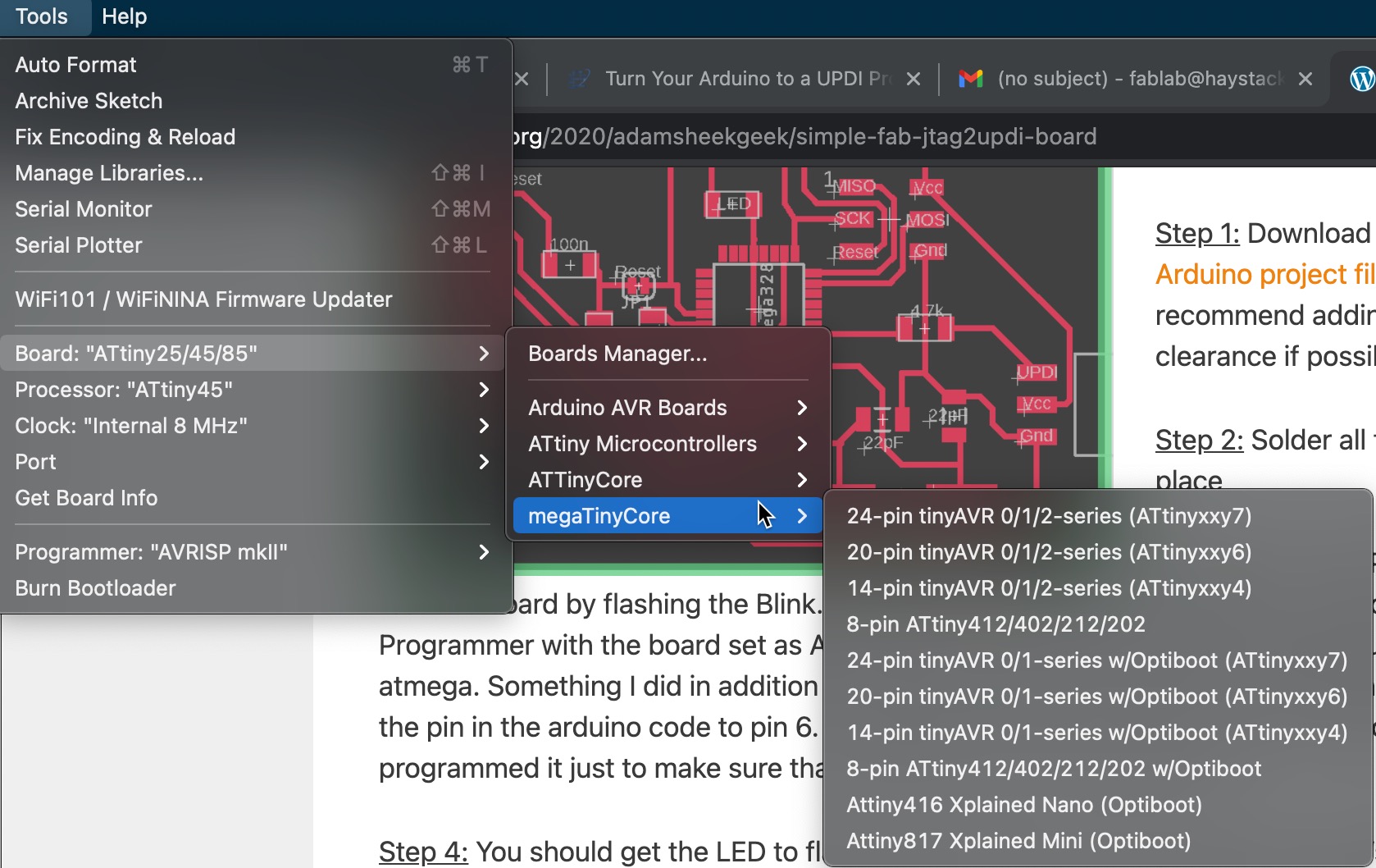
Board Manager > Install “megaTinyCore” package
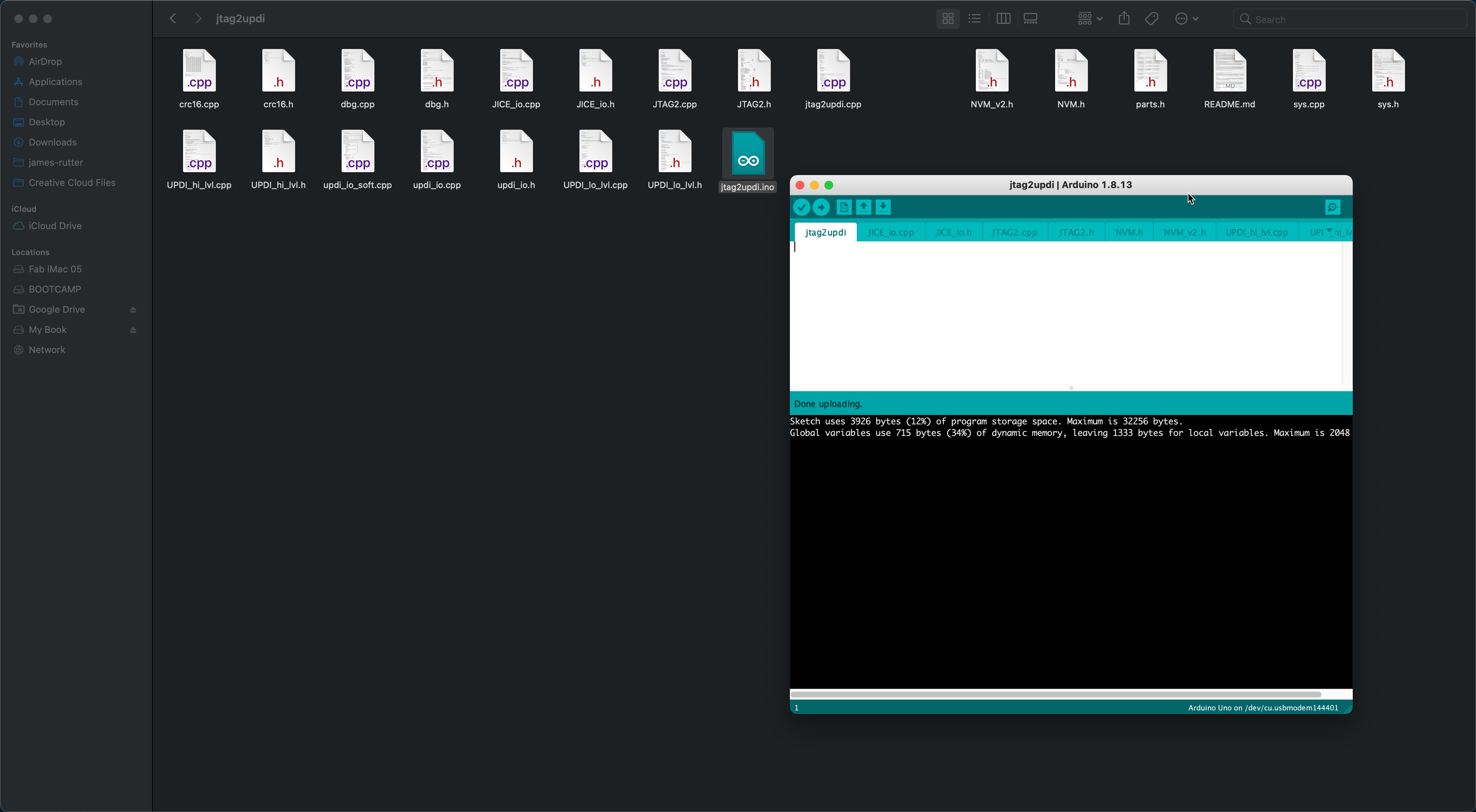
Download the (jtag2updi firmware)[https://github.com/SpenceKonde/jtag2updi]. This will need to be unzipped and renamed “jtag2updi” in order to match the .ino (sketch) file. Open the “jtag2updi.ino” sketch file located in the directory and you should see a bunch of tabs open, with the primary sketch being blank. That is okay. Upload to the Arduino UNO and this should turn the Arduino into a UPDI programmer.
References
- https://www.electronics-lab.com/turn-arduino-updi-programmer/
- https://create.arduino.cc/projecthub/john-bradnam/using-the-new-attiny-processors-with-arduino-ide-612185
- http://sheekgeek.org/2020/adamsheekgeek/simple-fab-jtag2updi-board
- http://sheekgeek.org/2020/adamsheekgeek/attiny412-general-purpose-blinky-board-and-updi-programming
- https://github.com/SpenceKonde/megaTinyCore/issues/24
- https://github.com/ArminJo/ATtinySerialOut
Last update: May 6, 2021