9. Embedded programming
This week was embedded programming, and while I would like to transition to using the ATtiny 1-series family of boards, all we have in our inventory is the ATtiny44/45. For my electronic design project, I designed a board using the ATtiny45 with a button and LED, so this week I am going to attempt to program the board using at least two different workflows/toolchains. The first of which will be using the make file via avr-gcc and avrdude programs to compile the code into a hex program and then flash that directly onto the board.
ATtiny45 Datasheet
Reading through the ATtiny45/V Datasheet gave me flashbacks from my electrical engineering undergraduate program over 10 years ago. It was slightly depressing to read through, skimming sections, and realizing that I remembered almost nothing from my college education. Of course, after reading a bit, certain concepts were familiar but there is so much going on in these chips that to understand what is going on under the hood is daunting.
Workflow 1: Programming through the CLI (Terminal)
I am using the AVRISP2 programmer simply to reduce the number of variables for things that can go wrong. As I build my up my process and become more confident, I will try using the Arduino as a programmer, as well as my original FabISP programmer.
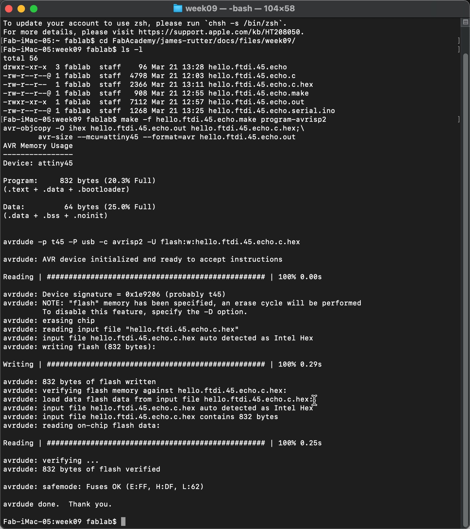
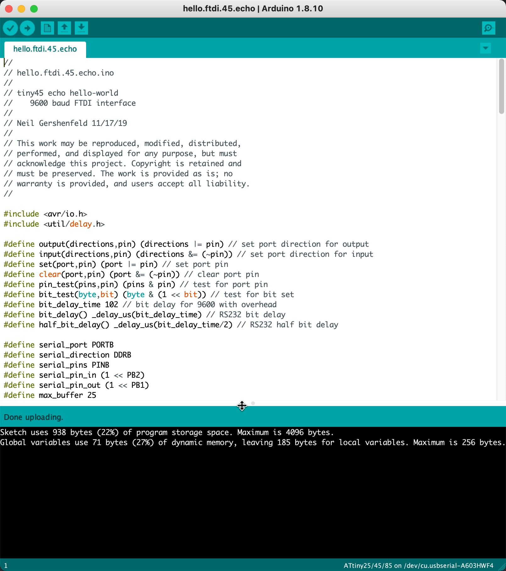
To test the process of compiling code and loading it onto the microcontroller, I am going to use the stock code that Neil provides on the lecture page. This is the hello.ftdi.45.echo.c and the hello.ftdi.45.echo.make files that I have loaded into my repo and will edit once I verify the programming workflow is all good. After reviewing the make file, it appears that I do not have to make any edits. So onto compiling.
make -f hello.ftdi.45.echo.make program-avrisp2
Running this at first led to an error message stating that the avrisp device could not be found or connected to. I ended up spending the next hour troubleshooting and figuring out that I needed to install the FTDI Drivers for macOS. I also needed to restart my computer, and then it ran smoothly when I booted it back up.
Workflow 2: Programming through the Arduino IDE
To evaluate another workflow-toolchain for programming microcontrollers, I used the Arduino IDE as another method for programming. I have used Arduino IDE for a long time now and it is a familiar environment so I am likely to use this moving forward with future projects.
Adding ATtiny Boards
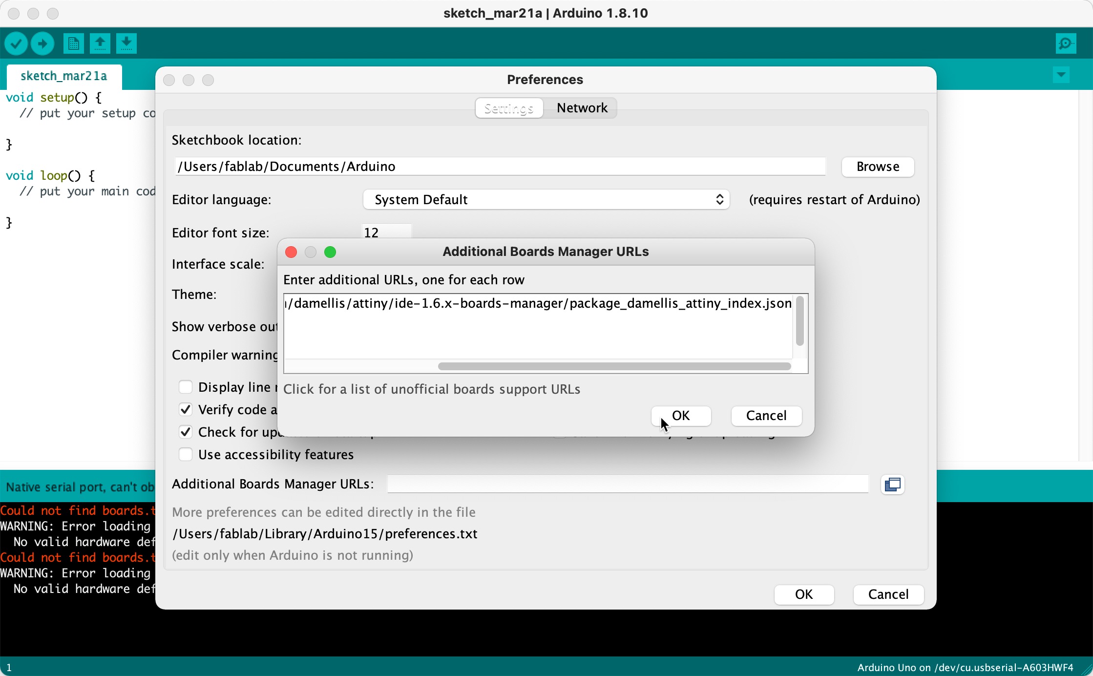
Arduino IDE does have the attiny boards out of the box, but it has the ability to add board managers/libraries from external sources. To do this, you go into Arduino’s preference window and load in the desired board library. You can browser all the currently available Arduino Board libraries hosted on git hub.
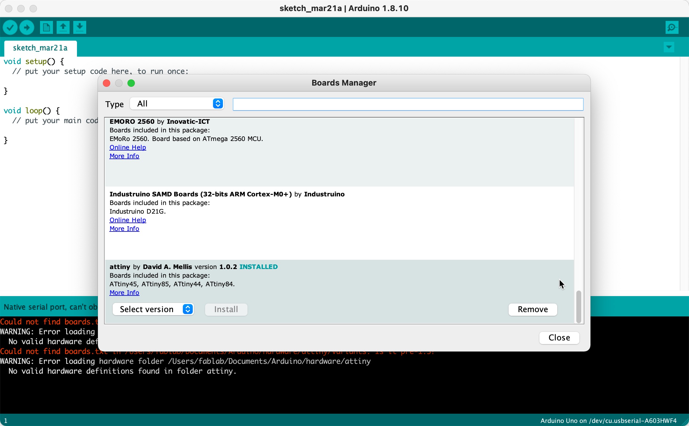
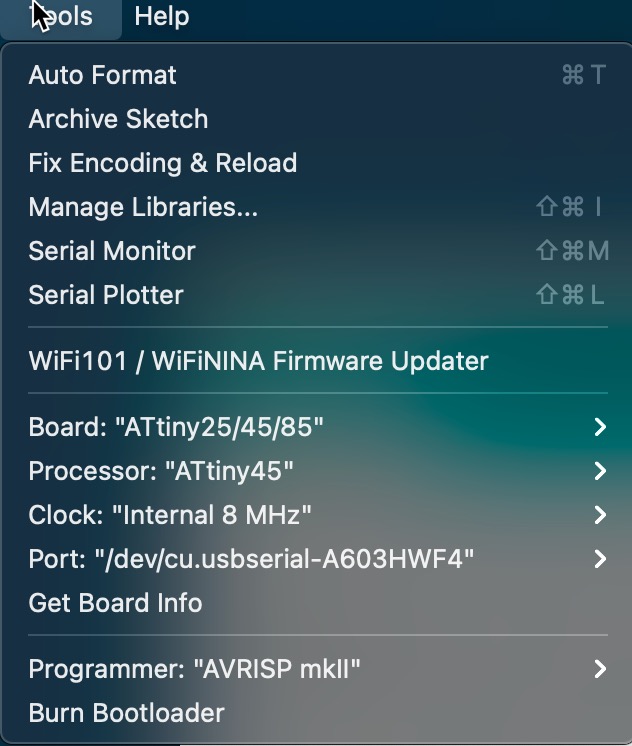
Install attiny board library into Arduino IDE and select to use attiny45 with the appropriate settings/parameters:
You need to specify the actual board/processor (45), clock speed (8MHz internal) and the programmer to be used. All of this was fairly easy to do, which I am sure is all the same information located in the Makefile.
After I had figured out the FTDI drivers and restarted my computer, uploading the code to the board via Arduino IDE worked perfectly. Below is what Arduino will look like when you successfully upload the code.
Programming LED + Button Program
Once I got the toolchain setup to program the ATtiny45 with Arduino IDE, I decided to use the Arduino programming language to begin my initial coding experiments with the chip. This will allow me to work faster and verify that everything is working as expected.
Button + Blink Code
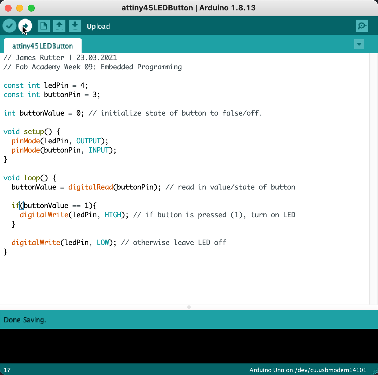
Reading in a button and controlling an LED is something I have done a lot over the years, so I was able to put the code together fairly quickly in Arduino. The same could not be said for writing this program in C, which after looking through Neil’s sample echo code in C, I decided that my time was best spent using Arduino to get this assignment done. There may came a time and place where I want to dive deeper, but now is not that time.
Anyways, the code compiled just fine but did nothing once I uploaded to the board. It just sat there, doing nothing. This is usually what I expect when I try things out for the first time. So onto the the debugging and troubleshooting.
Debugging Hardware
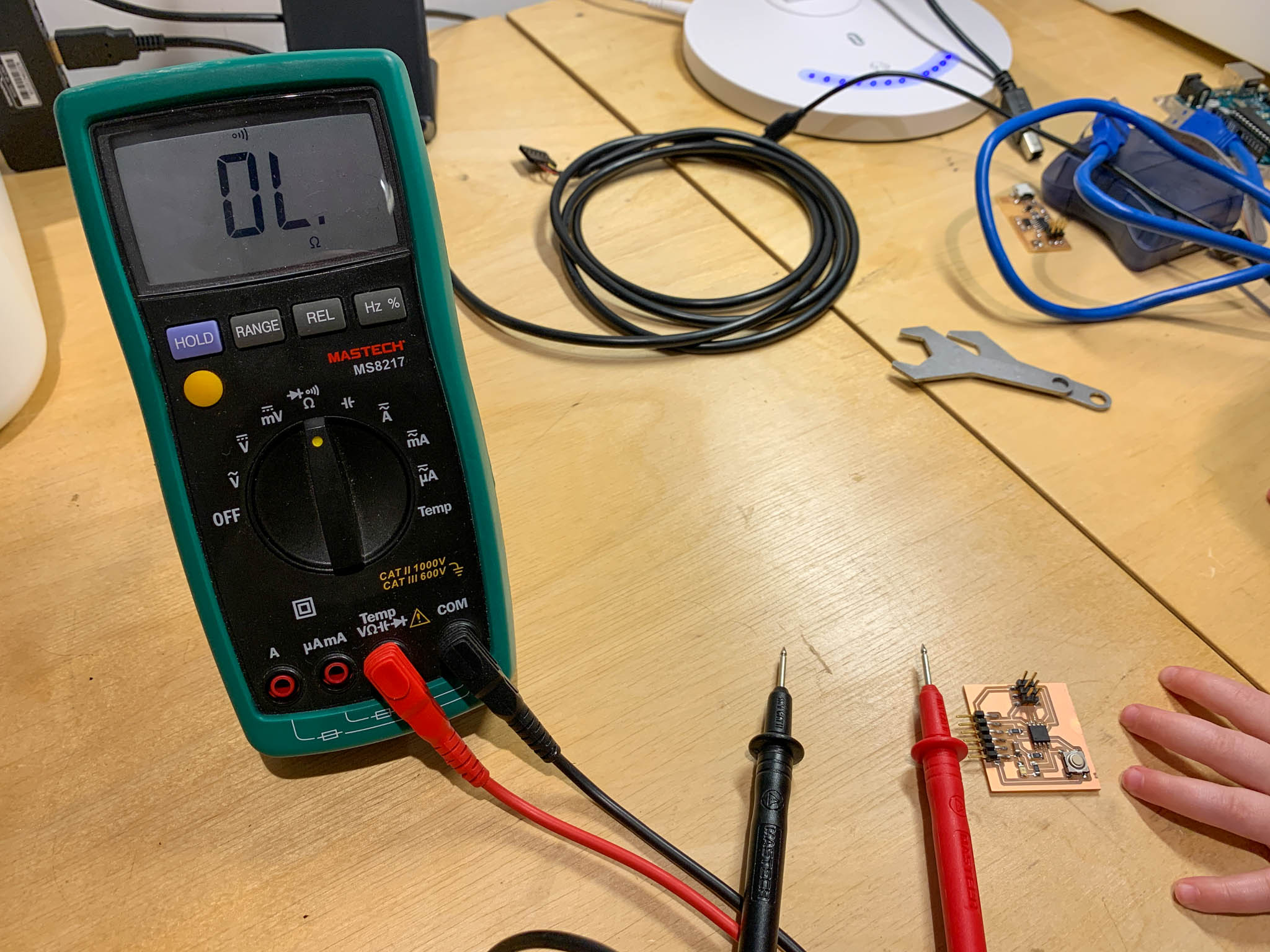
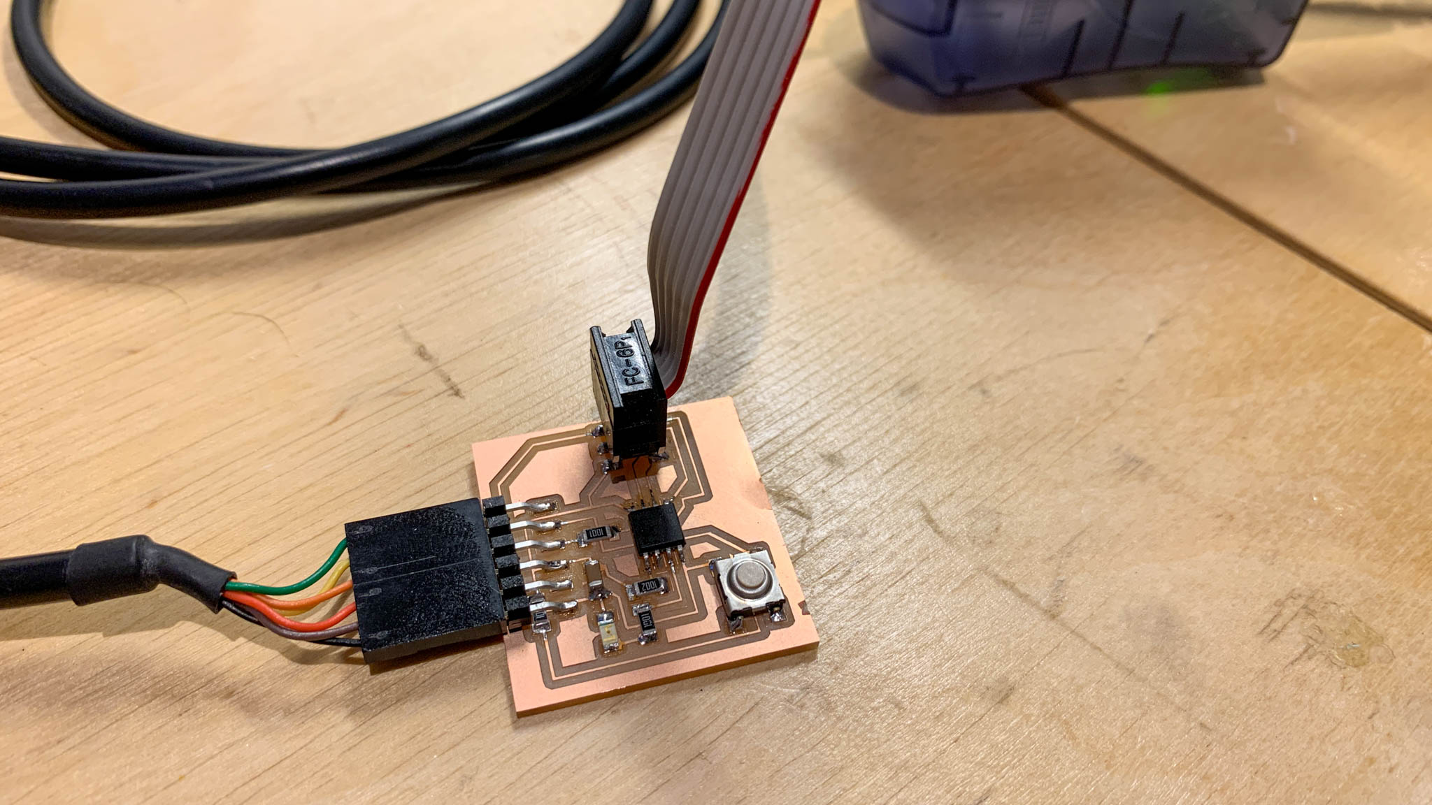
I had to do some troubleshooting or debugging, which is to be expected when dealing with electronics. I was fairly confident in my code that I first checked the circuit using a multimeter and 9V battery to see what was going on. To do this, I used a multimeter to check for continuity between particular components of the circuit. I found one open circuit on the button and fixed it with some addition of some solder.
Note: the small child-size hand creeping into the picture above. Probably not sage parenting advice to let your kid watch you debug circuits. Though, this project is ultimately for her to play with, so she should help a little bit.
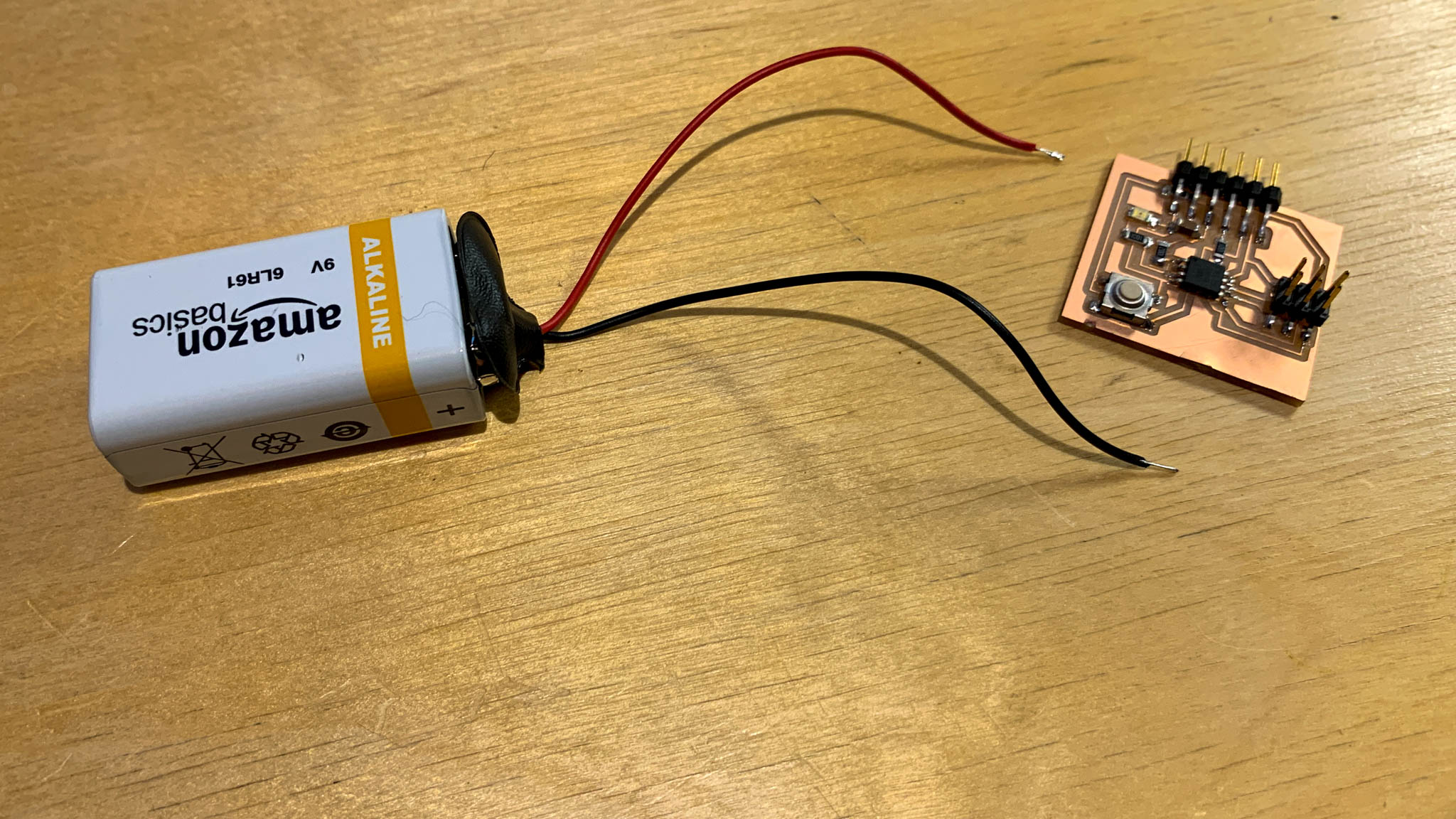
I know this is also probably frowned upon, but I will use a 9V battery with leads attached to active parts of a circuit. In this case, I wanted to make sure the LED was lighting up okay and wasn’t broken or wired backwards (wouldn’t be surprised if that was the case). I was careful to apply the 9V to the current limiting resistor and not directly on the LED, so it light up just fine and worked as expected.
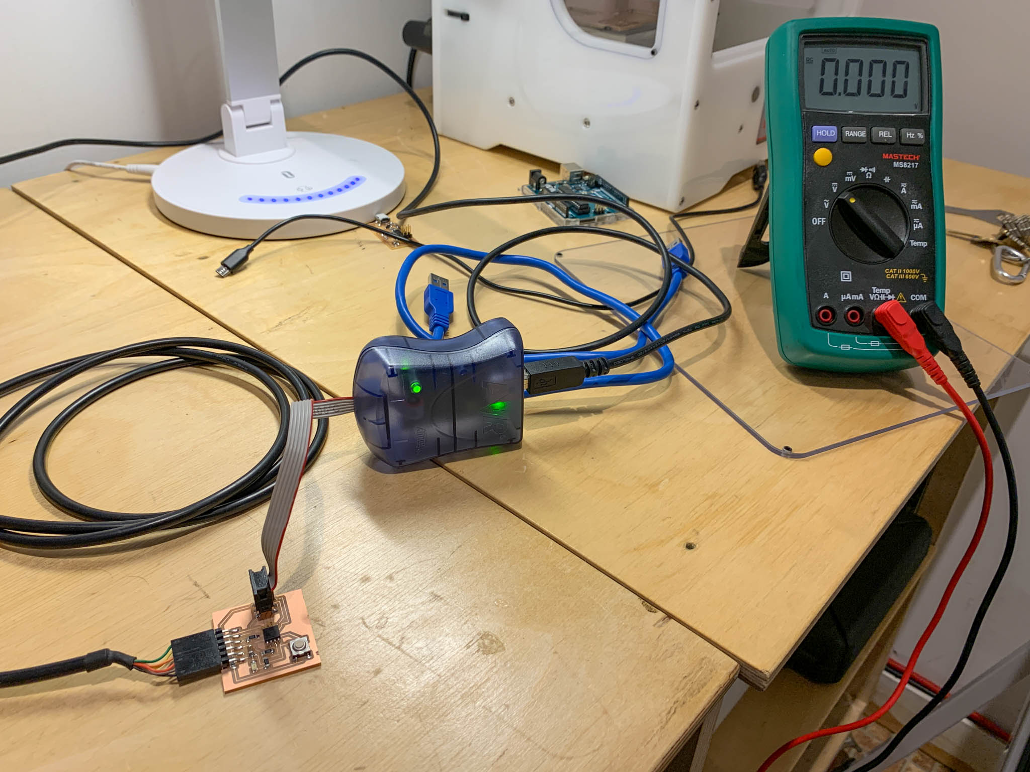
Another shot of my troubleshooting setup. I spent about an hour making sure my circuit was designed properly, using the schematic to verify everything. I was now fairly confident I had a functional board, and the code was uploading to the board so the I felt the microcontroller was okay as well. Back to the software for more testing.
Working Program
As it turns out, I had addressed the wrong pins in software. So, despite how simple I thought the code was going to be. I had my output pin set incorrectly. Once I set the output pin to #4 on the board, the LED light up and began blinking. My first program was to just blink the led, without any button interaction.
Reverse Logic
Once I got the correct pins, I had reversed the logic of the button and so when it was pressed, the pin went LOW instead of HIGH. This is probably how I designed the pull-up / pull-down resistor circuit. I probably designed a pull-down so the pin gets pulled down the switch is closed. I am not sure exactly if that is what I did, but I will go back and evaluate later. Below is the video of the logic flipped.
Correct Logic - Final Program
Correcting for this in software is simple. I just waited for the pin to go LOW instead of HIGH to turn on the LED, and the issue is fixed when the next version of coded is uploaded to the board.
Group Assignment
Charlotte Latin’s group work can be found here. However, since I am working independently, I compared microcontroller architectures myself.
ATtiny45 (aka “tiny45”)
According to Neil during the lecture, the tiny45 is aging out and thus should eventually be phased out of the inventory. However, I ended up using this since our lab as it in stock. The workflow, described above, is relatively straight forward but requires
ATtiny412 (aka “tiny412”)
I later got access to the tiny412, thanks to Charlotte Latin for shipping them up to Deer Isle, and was able to compare this agaisnt the tiny 45.
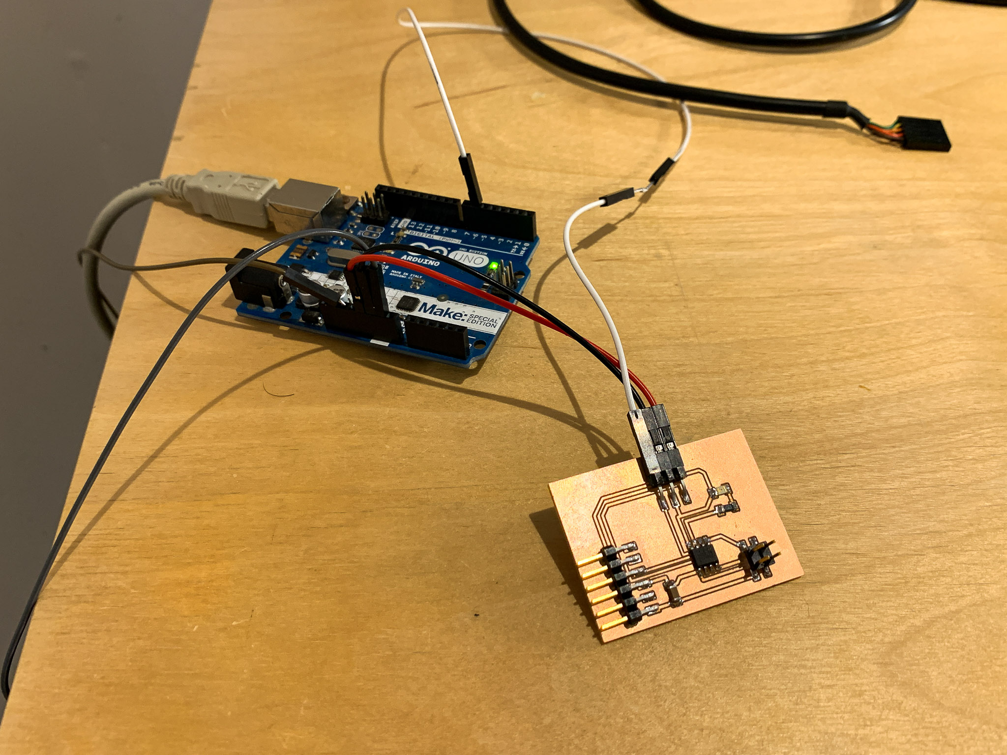
The ATtiny412 is part of a newer family of AVR-tiny microcontrollers and has a couple of performance improvements from the tiny45. The biggest difference is how you program the controller. The tiny412 uses the Unified Program and Debug Interface (UPDI) to program the computer on board. This is done through a single pin and can be easily configured with a spare Arduino to function as an ISP programmer. This removes the need for dedicated programming hardware and simplifies the board design.
The board also appears to have better internal clocking than the ATtiny45, which had issues using the internal clock to manage delay-times on my blink LED program in a prior week.
Files
References
Arduino Embedded Programming Tutorial
Neil’s ATtiny45 Programming Video
Diego Santa Cruz Meon’s Documentation