13. Output Devices
This week I design and programmed a RGB LED to pair with my temperature sensor. Until I build my final oven, I am going to have the RGB LED color change with the relative tempature measured by the thermistor. Neil’s website provides a template for using an RGB LED, which I used to begin my design process. My new ATtiny412 and 1612 boards have not come in yet, so I am going to stick with the ATtiny45 for this module. Maybe for the wildcard week I will get setup with the new AVR boards.
Designing the Board
I did this in Eagle, following Neil’s design for the most part. There were a couple of new features that I had to work through. First, there was the use of a 5V voltage regulator and an external power suppy using a 2x2 pin header. I believe this will allow me to power the board and circuit with a 9V power supply (or something else) and ensure that a clean 5V is supplied to the board.
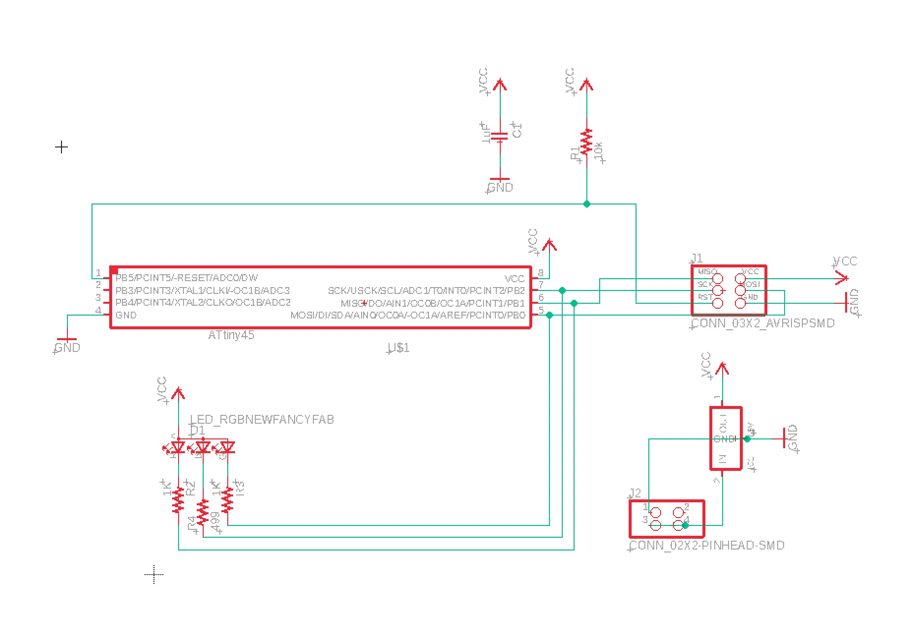
The above circuit was fairly straight forward to design. I tried to create custom labels for the 2X2 pin header so that it was clear when doing my board layout and soldering which the power and ground pins were.
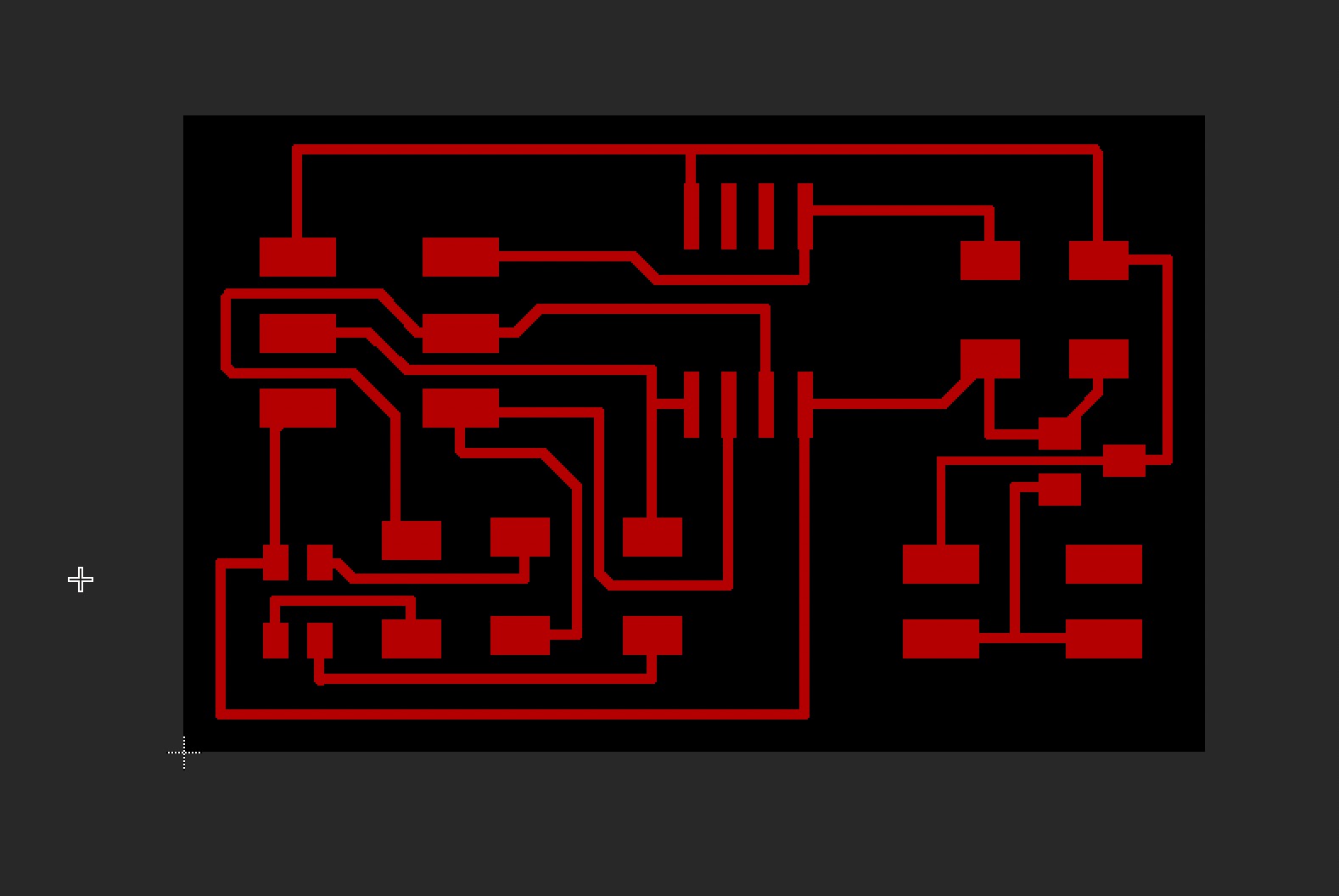
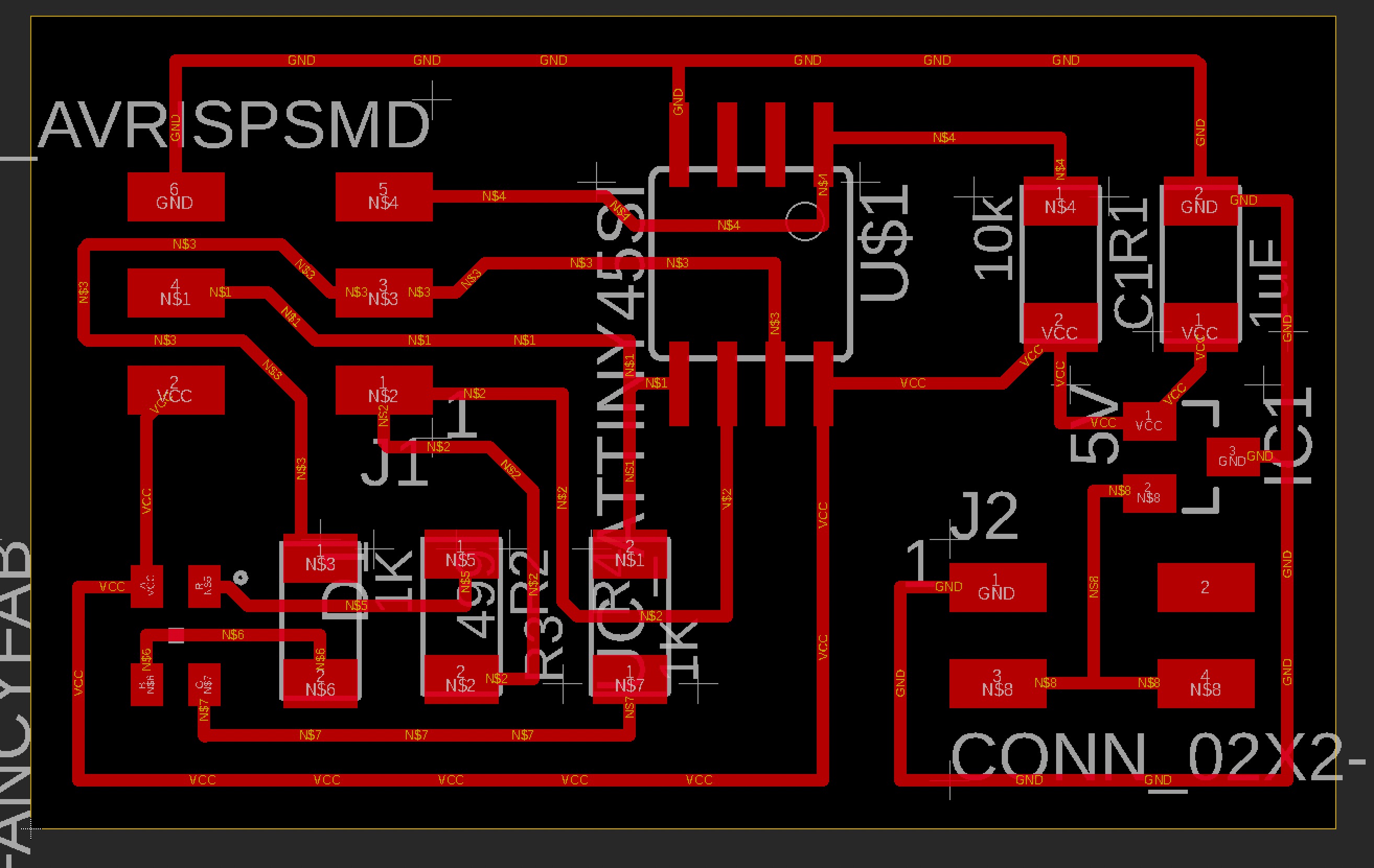
The board layout was not that difficult because I did not keep any of the input hardware on the board. For simplicity, I just want to get the RGB led working with the microprocessor. This is inline with a circular or spiral development cycle, in which I will add layers of complexity the further I get. Start simple and then add more layers or features.
I ran into an issue with the Bantam Tools CAM software. It was not happy about the trace spacing within the voltage regulator, even though Neil was able to do this on his board, I had to tweak the settings of my trace width from 12 to 6, and that still didn’t work. Therefore, I re-routed the traces, which was fairly easy but did my make my board slightly bigger. Oh well.
Milling the Board
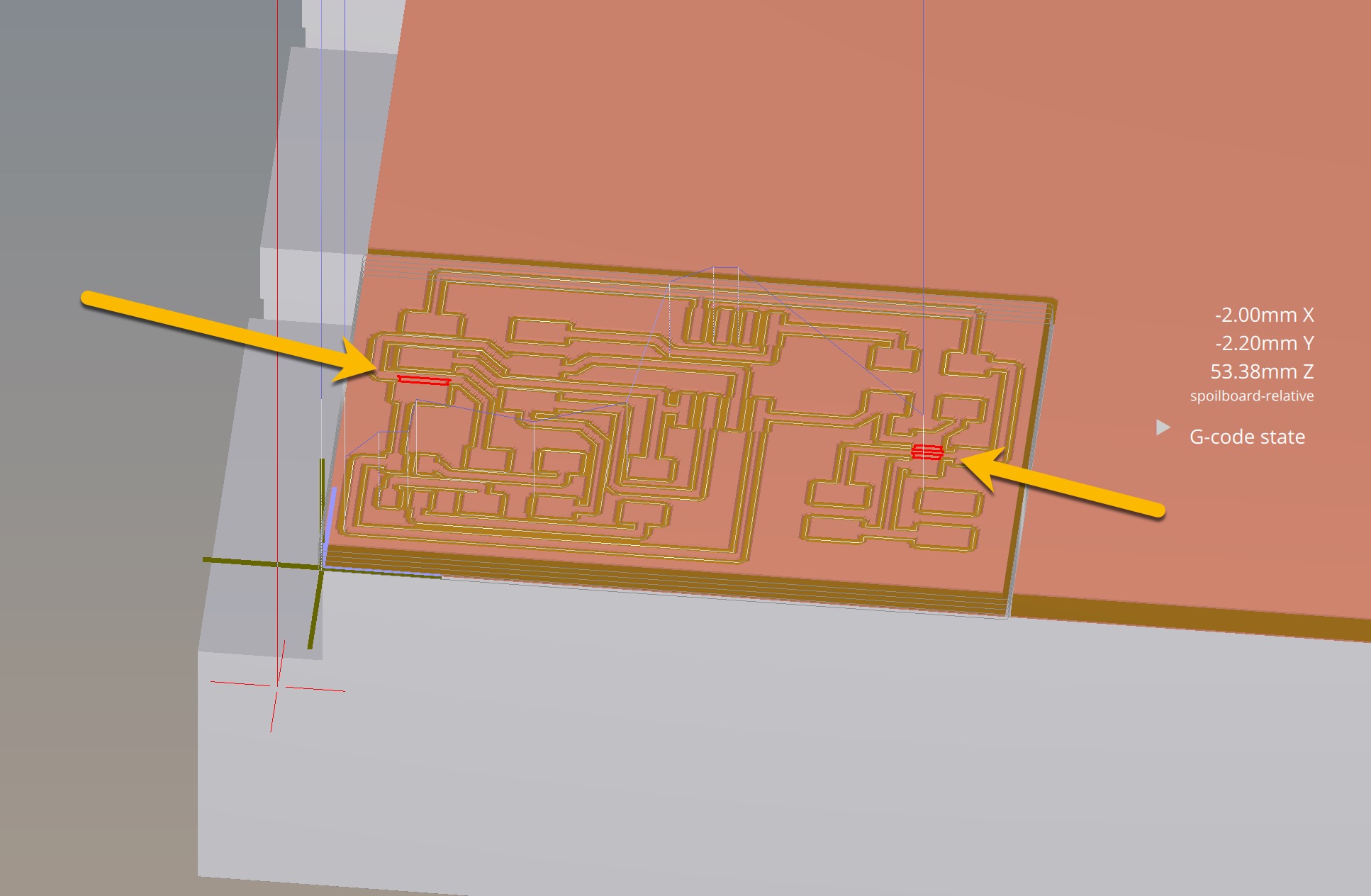
I have been using Bantam’s latest software package with my circuit workflow but ran into scaling issues out of Eagle and into Bantam (see input device week). After talking with Tom and David about this issue, they informed me that I could use the .BRD file straight from eagle and not have to deal with the PNG export. This was an attractive new workflow that eliminated a couple of steps. However, the new version of Bantam does not handle the file well and it was difficult to parse out the toolpaths intended for the 1/64” tool and the toolpaths for the 1/32” toolpaths.
Rolling Back to Legacy Software
Tom and David also recommended that I use the legacy version of Bantam’s milling software. I tried rolling this back on my iMac but the program did not want to run. It might be a compatibility issue with the most recent version of macOS Big Sur, but I am not entirely sure. In any case, I ended up installing the software on a spare PC laptop and it runs okay on Windows.
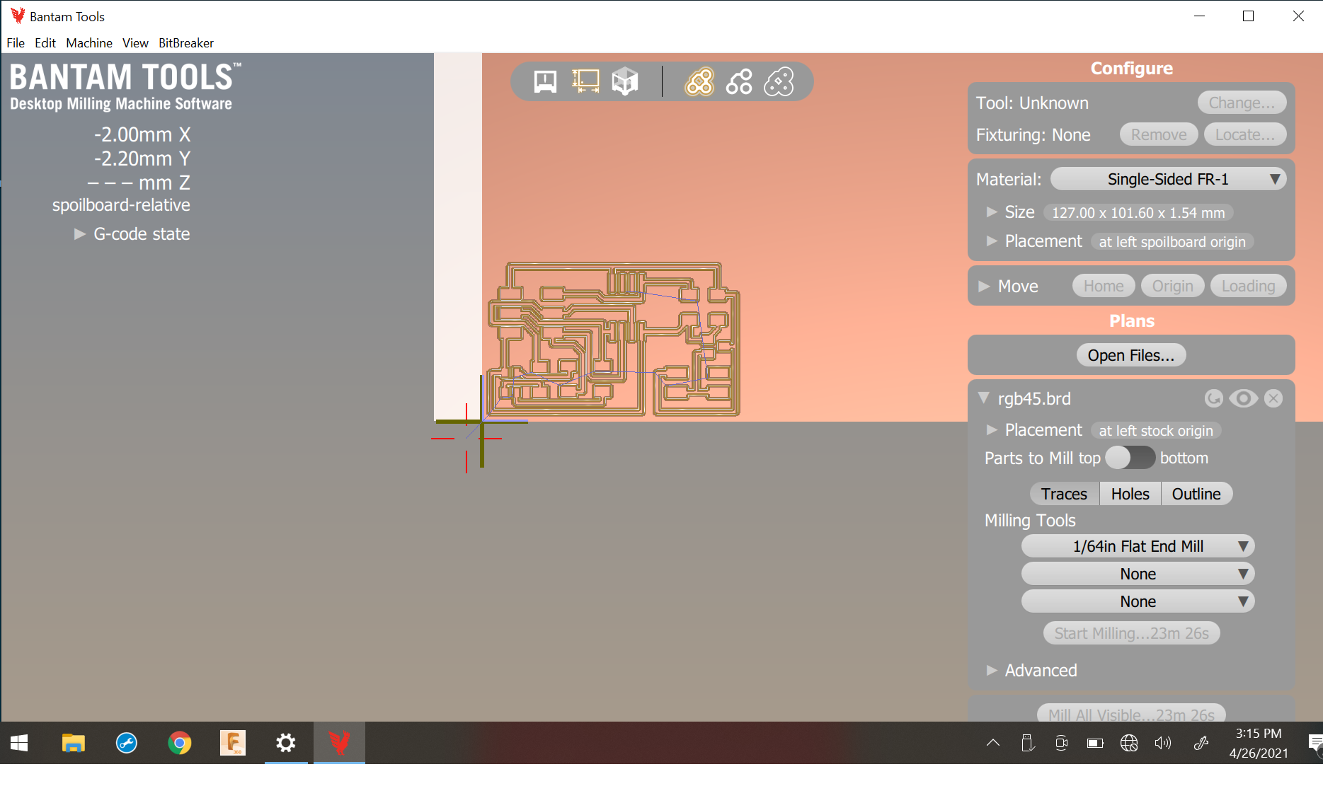
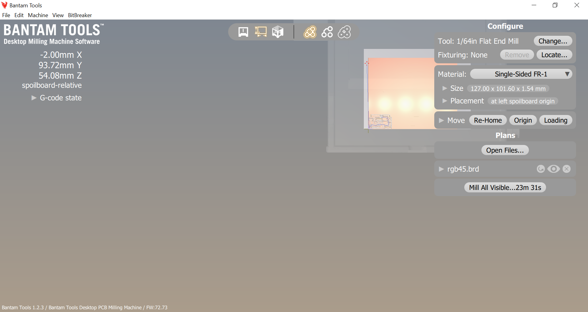
The software is actually easier to use than the newer version. All the settings and options are in one column on the right-side of the screen. I did the job in two passes. One with the 1/64” tool and the other with the 1/32” tool.
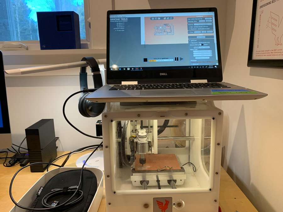
Here is a nice shot of my improvised setup using a Windows PC laptop resting precariously on top of the machine. Would not recommend, do not try at home.
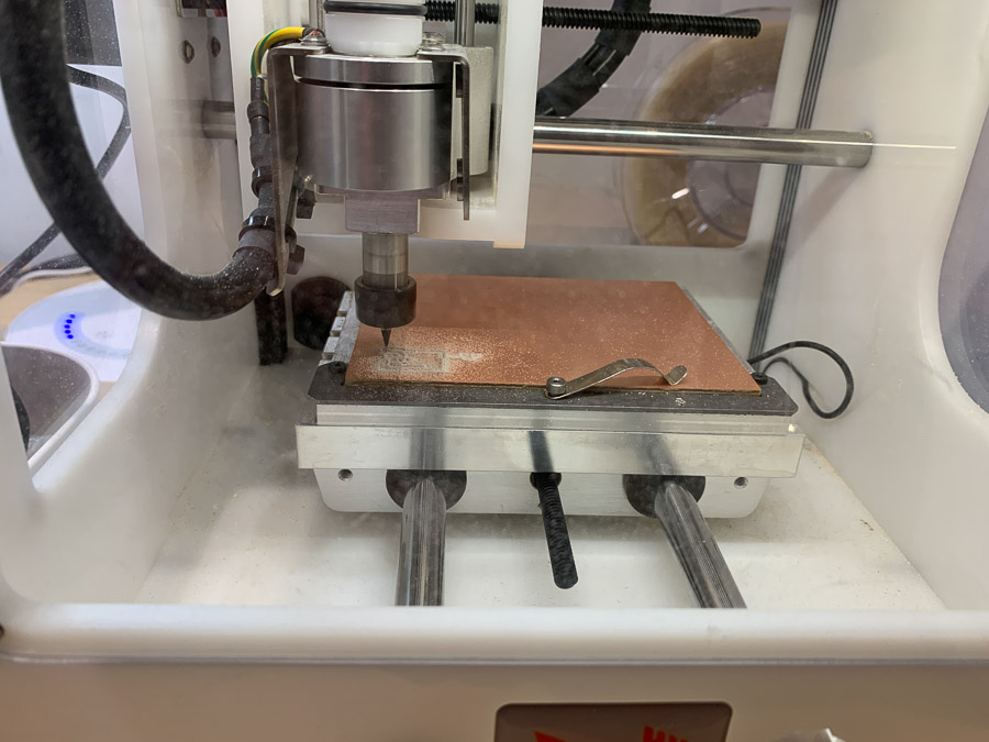
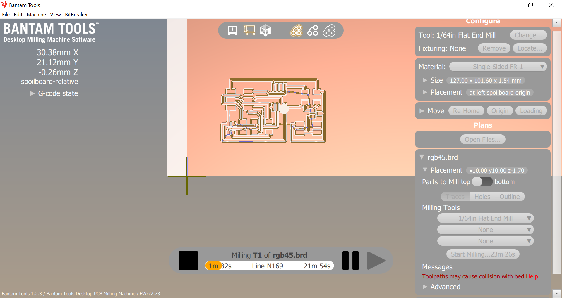
Everything went according to plan. My biggest issue with the software is that the settings (feeds, speeds, pass depth) do not appear to be editable and the program takes a lot longer than the fab modules gcode file. Not sure exactly why, but I will probably investigate a bit further on my next board.
Soldering
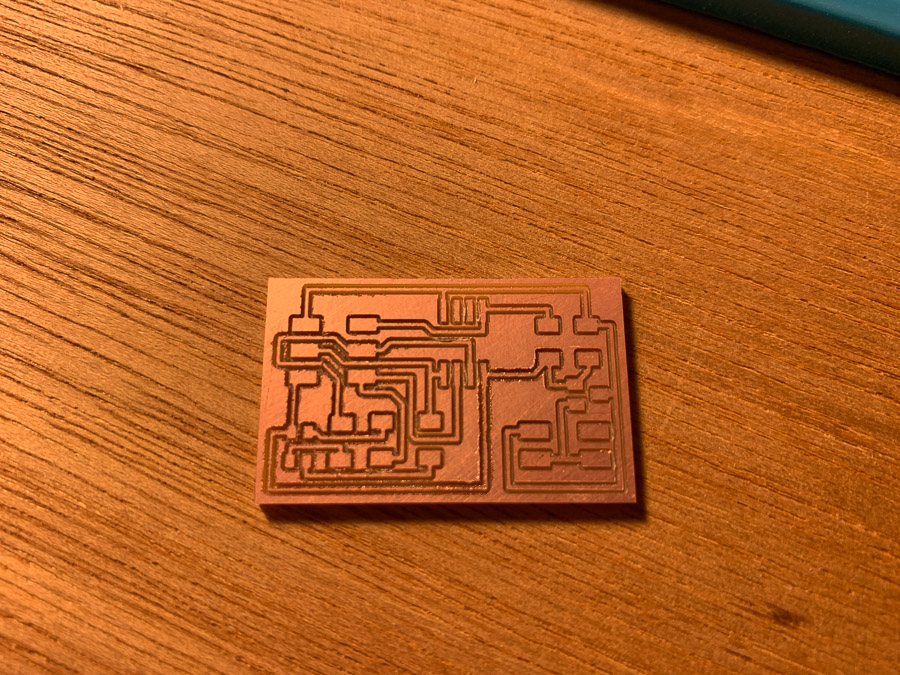
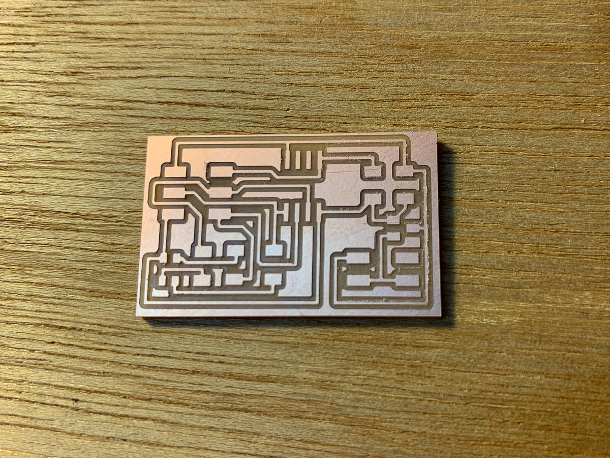
The above photo is a good example of what a board milled with a dull tool looks like. The edges of the traces are a bit rough. The engravings are not clean or sharp. I cleaned it up a bit before heading over to the solder station.
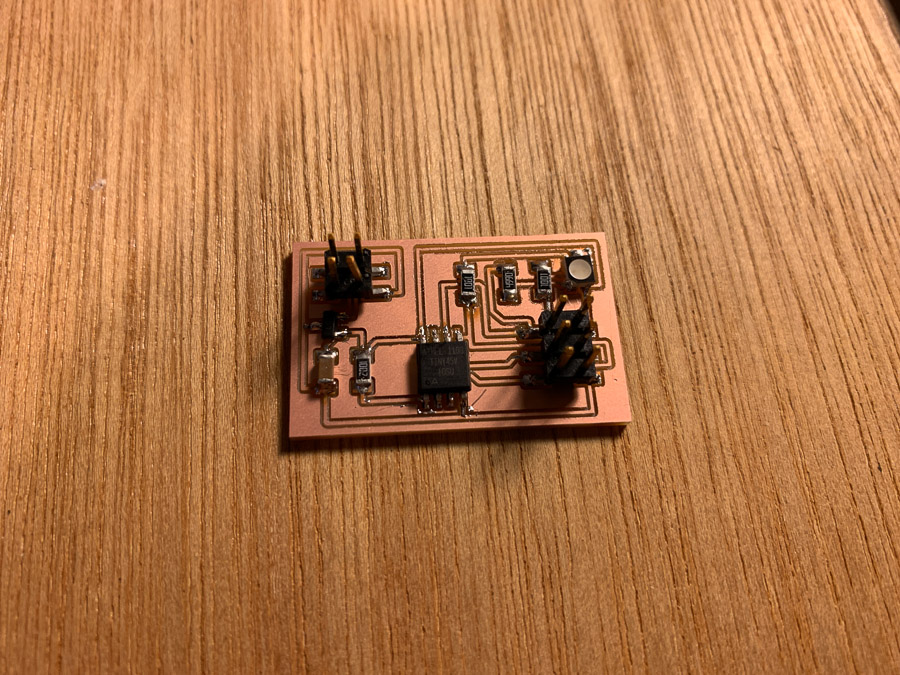
Soldering up this board was a little tricky. Mostly, the RGB LED leads are tucked underneath the component and almost would require me to use a reflow solder oven setup. However, I was able to solder everything up mostly.
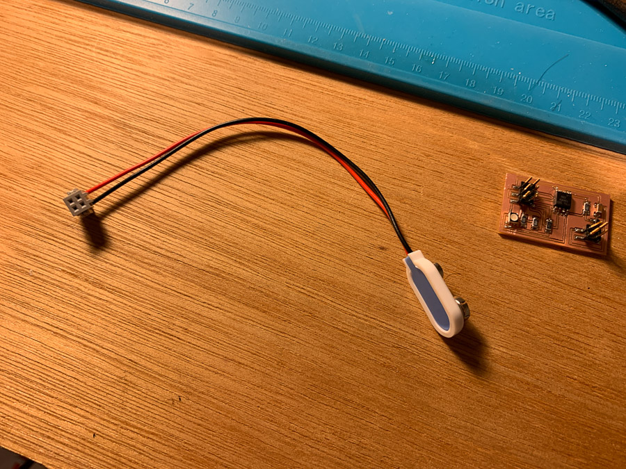
I made a 2x2 header adapter to plug into a 9V battery snap to power my board. I did not have an external power supply handy, and this board will not use a lot of power, so it should last a while.
Troubleshooting
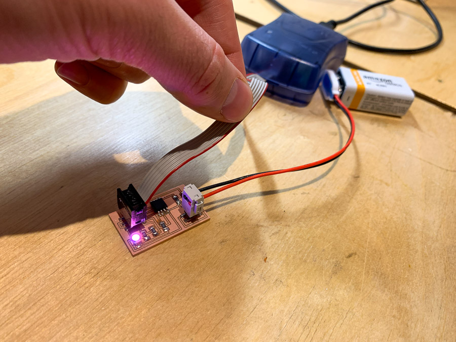
Okay, so this is where things get strange. I plug everything in and the program is not loading via Arduino. I am getting strange error messages and so I assume this has to do with my board. I bust out the Multimeter and turn it on the continuity tester to begin looking for a short. I quickly find an issue between the RESET pin and the rest of the board. There appears to be a short and I tried for a while to resolder and tweak the board to get the issue resolved but had no luck. Fortunately, the LED did turn on, even though it wasn’t programmed to turn on, so that is a good sign that something is working.
Redo
I had to re-mill and solder my board since the last one had a short and it was too difficult to fix with all the components stuck on the board. In fairness, I did try to use solder wick, but I ripped up traces and made a mess of the thing. It took me about an hour to redo everything and get the board fabricated and soldered.
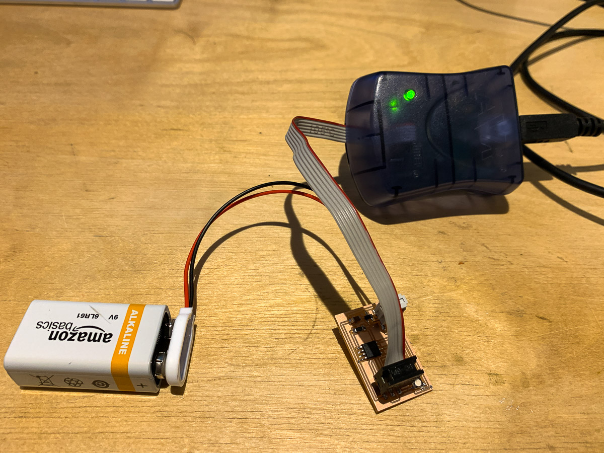
This time, I made sure to check connections carefully and everything came out as expected. I connected my programmer and got the happy green light. Uploading code in Arduino IDE also worked as expected. Life is good.
Coding


Final Test Program
Here is a video of my final code cycling through the different colors. I may add to this once I get my thermistor connected and running. My plan will be to use PWM to ramp up the color as the tempature changes.