11. Input devices
Group Work
The group work documentation for this assignment completed by the Charlotte Latin students.
This week, I decided to work with a temperature sensor as my input device. We had the NTC thermistor sensor in our lab, so I went with this as my input device. A thermistor is a special type of resistor that changes its resistance based on the ambient temperature around the device. If you configure the device properly with other resistors, you can configure the input of the microcontroller’s AD pin to read in a changing voltage, which will get converted into a digital number. This can then be used by the microcontroller in a number of ways.
Final Project
My final project is evolving into a low-temperature oven that can bake polymer clay into simple ceramic projects. Because of this, I am going to try and tackle the temperature sensor component and learn as much as I can through this assignment about how to thermistors.
Board Design
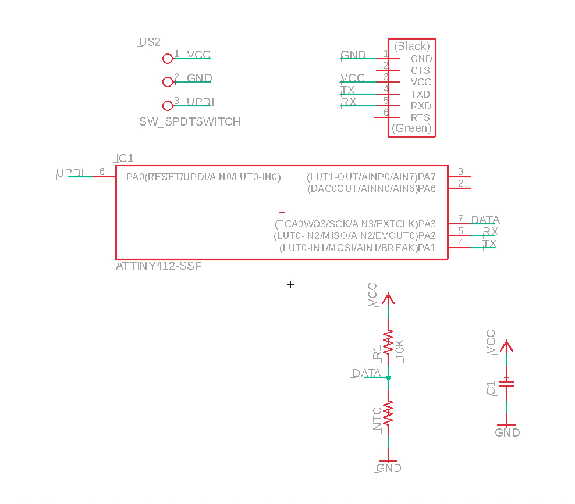
I originally tried to modify my LED + Button board from week 07 and add the NTC into the circuit, along with the additional resistors. After a couple of attempts, I ended up creating and designing a board with just a temperature sensor, similar to Neil’s example posted on the fab academy website. I ended up with the following schematic:
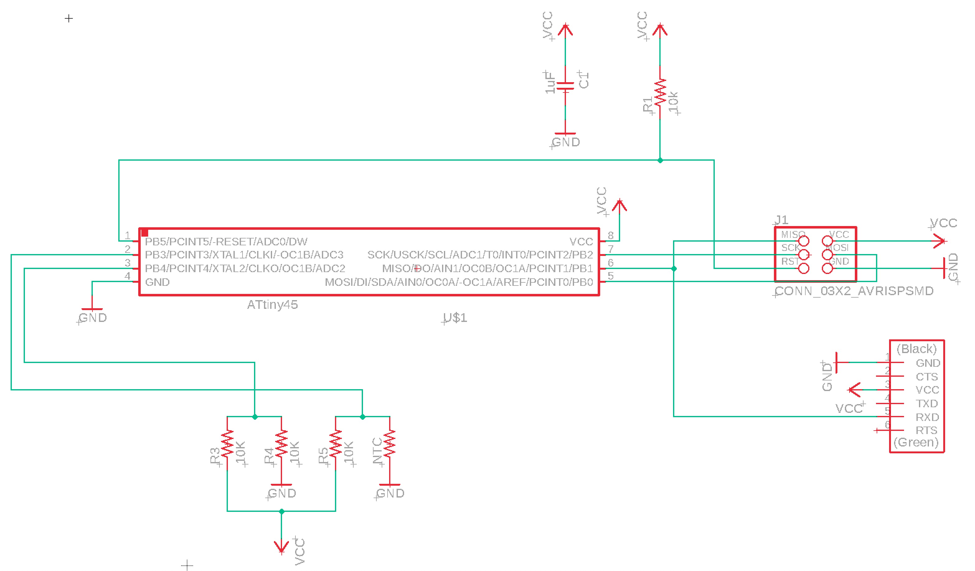
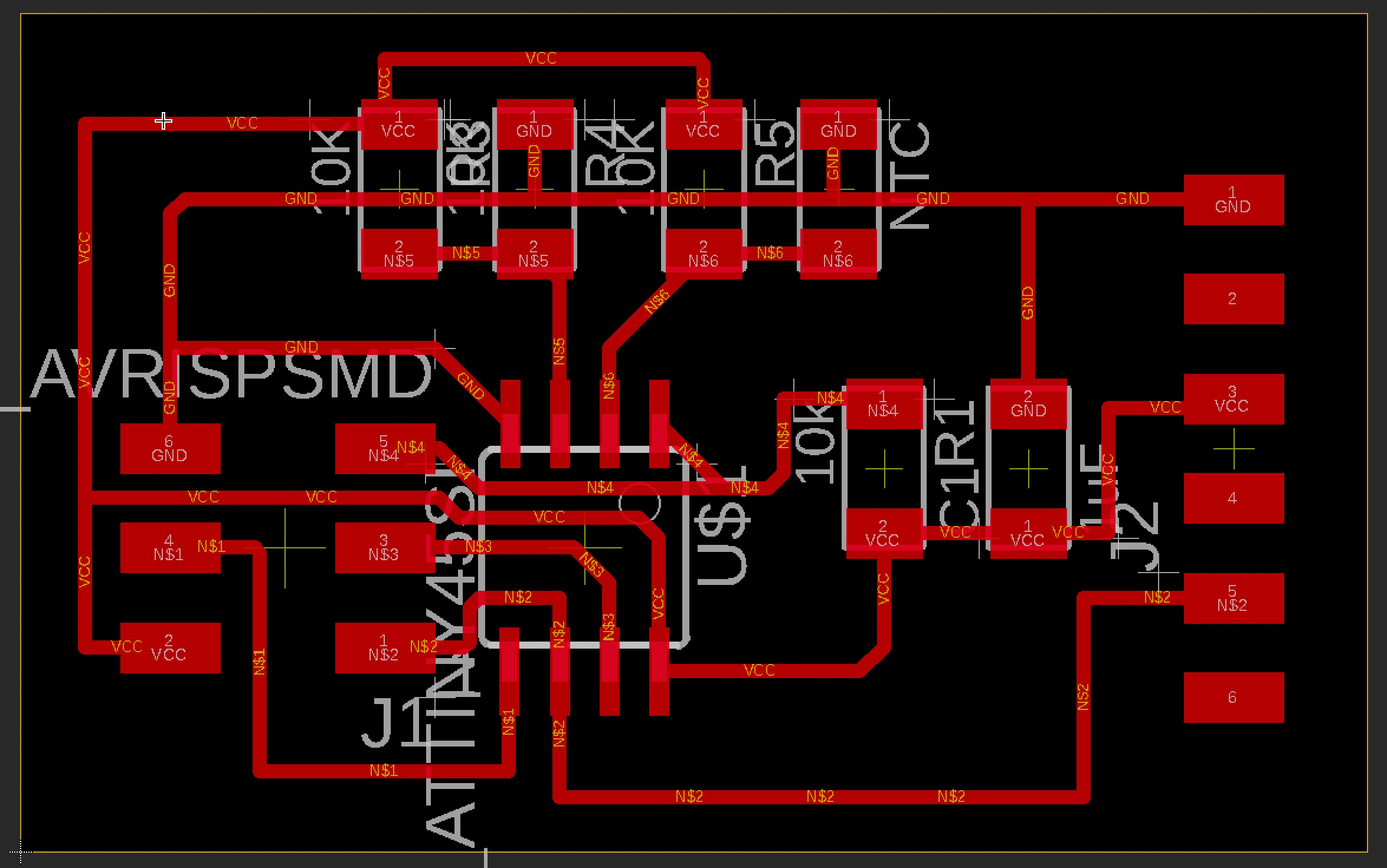
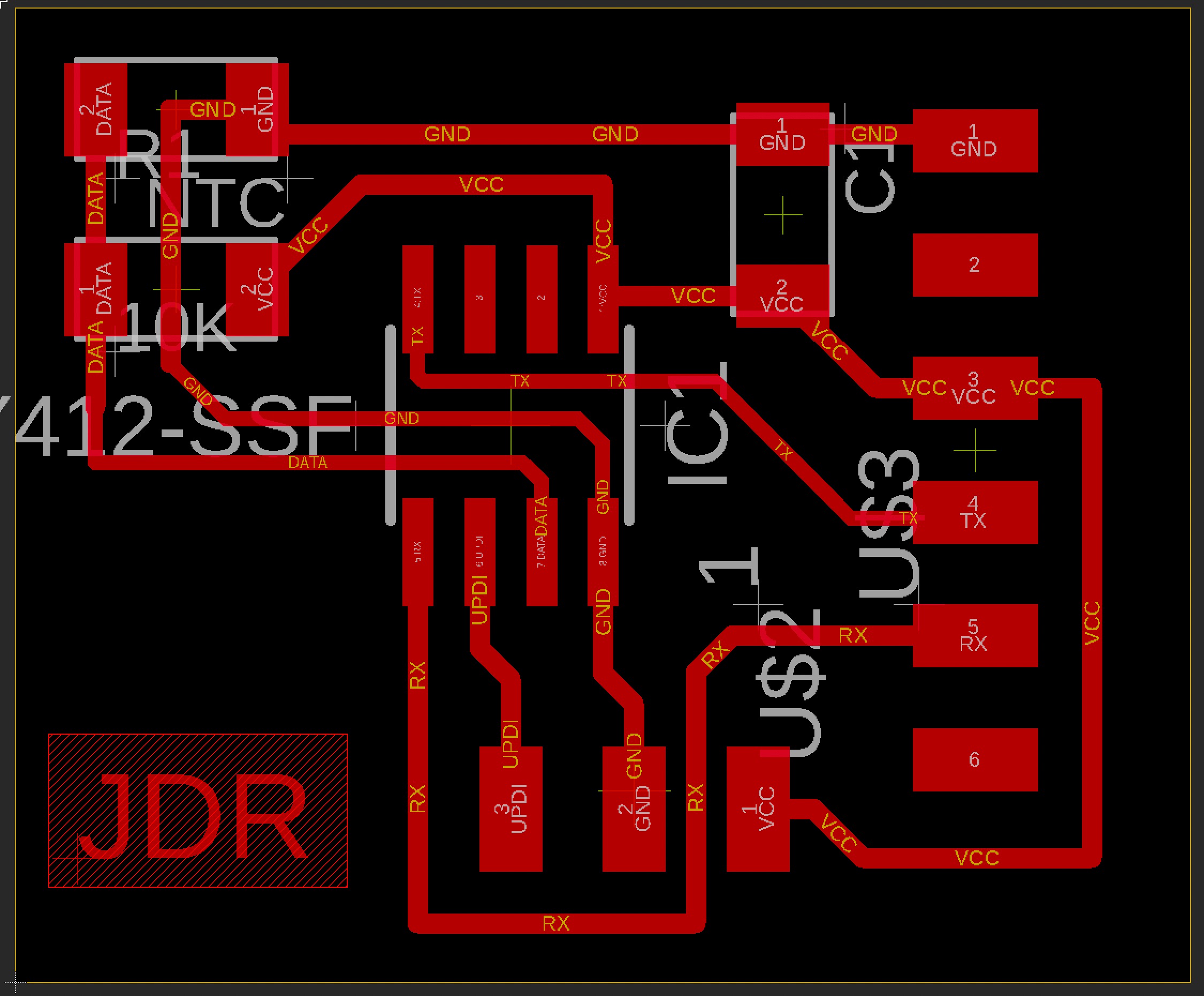
As well as the following board layout for the board. I relied on Neil’s layout to help figure out the most optimal path for all the traces/routes. As a result, my board looks suspiciously similar to Neil’s.
Export Issues
I ran into some issues exporting the PNG to Fab Mods and trying to import the .NC file into Bantam’s CAM software. There was a scaling issue between all three programs and I could not figure out what was going on. In a later week, I ended up reverting my software to the original Bantam CAM program and using the straight .BRD file that Eagle saves and was able to avoid the scaling problem altogether.
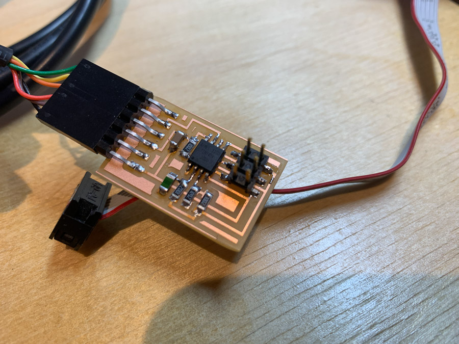
Milling Board
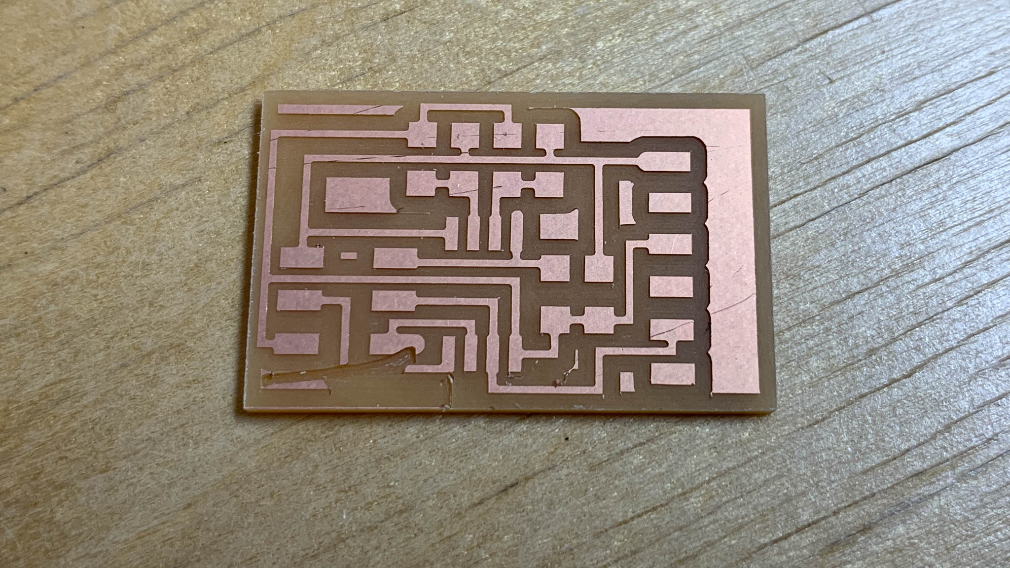
My first attempt at milling did not go well. Something happened with the milling, I believe the
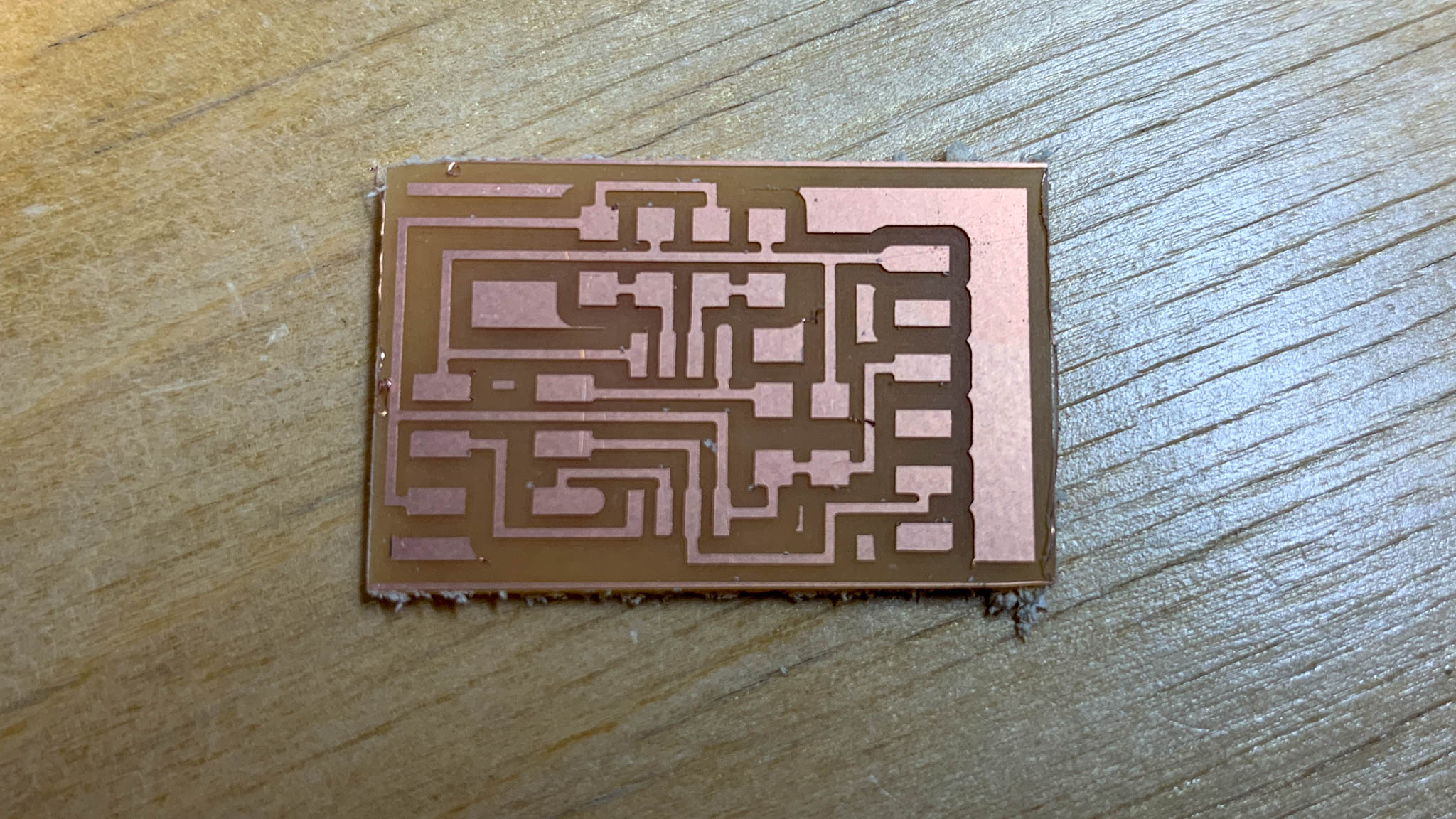
Next attempt worked out well.
Program
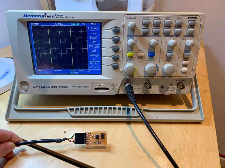
I started by uploading Neil’s stock codefor the NTC temperature sensor. This uploaded to my board without any issues, but when I opened the Serial monitor in Arduino, I was not getting anything useful back from the board. So I busted out the oscilloscope to take a closer look at the signal coming out of the NTC thermistor.
ATtiny45 Temperature Files
New Design with ATtiny412
After failing to make much progress with the SoftwareSerial library on the ATtiny45, I decided to redesign a temperature board using the ATtiny412 instead. This is a more modern microcontroller and has hardware serial built onboard the chip. It also uses the new UPDI protocol for programming which makes things easier.
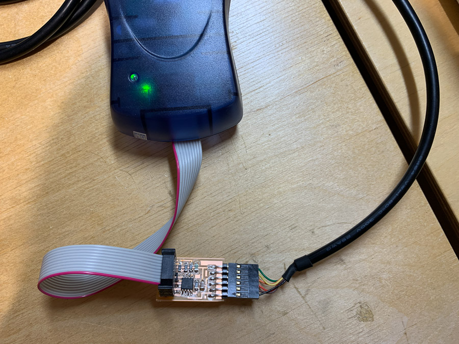
Programming
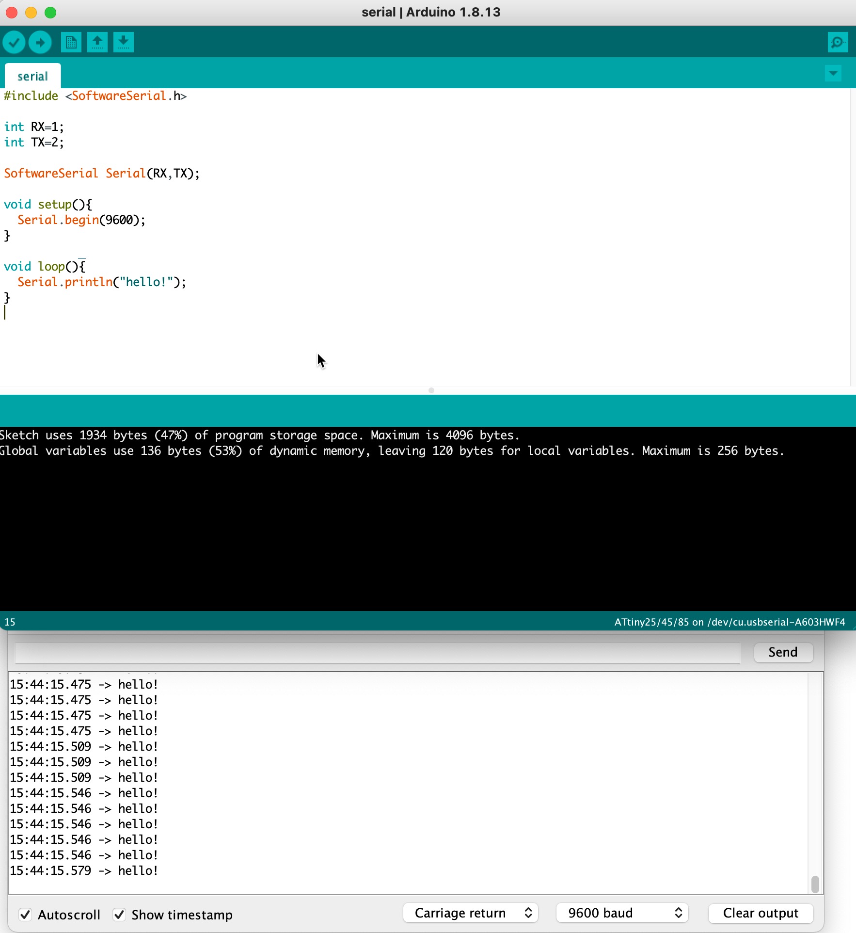
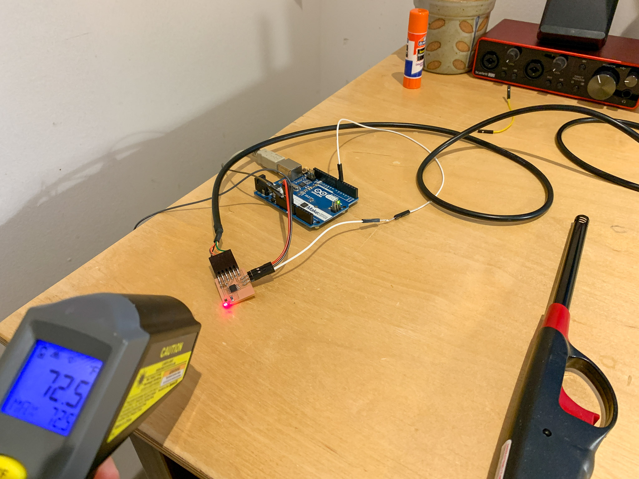
A couple of notes here: I ended up having to use the Software Serial library to get serial communitcation working via FTDI cable. I also experimented with calibrating the sensor data and so far still have some bugs to work out. However, I was able to calibrate the resting / default tempature. Currently, the tempature is decreasing when it should be increasing. I think I can fix this by switching the placement of the resistor/thermistor for the voltage divider, but I will do this later when I make my final board for my oven.
I made good use of this Arduino Tutorial to help guide my tempature forumula. Again, I probably am missing something with the tempature going down and not up, but it seems to be working for the most part.
#include <SoftwareSerial.h>
SoftwareSerial mySerial(2,3); //RX, TX

const int sensorPin = 4;

int Vo; // voltage across thermistor and 10K resister (R1)
float R1 = 10000; // fixed value resistor
float R2; // resistance of thermistor (variable)

float logR2, T;
float c1 = 1.009249522e-03, c2 = 2.378405444e-04, c3 = 2.019202697e-07;

int Tf; // display units in farenheight

void setup() {
  mySerial.begin(115200);
  pinMode(sensorPin, INPUT);
}

void loop() {

  Vo = analogRead(sensorPin);

  R2 = R1 * (1023.0 / (float)Vo - 1.0); // steinhart-hart equation

  logR2 = log(R2);

  T = (1.0 / (c1 + c2*logR2 + c3*logR2*logR2*logR2));
  T = T - 273.15;
  T = (T * 9.0)/ 5.0 + 32.0; // convert to farenheight unit degrees
  T =
  Tf = (int)T; // convert to integer for saving memory (warning: will round to the nearest whole number).


  mySerial.print("Tempature (F): ");
  mySerial.println(Tf);

}
I ran into some memory issues with the serial print commands. It turns out, printing a floating point number require a lot more memory than printing an integer, so I converted the final tempature number back to an integer. This causes some loss in precision, but for my purpose, this should not matter. I have access to the precise temp for my eventual control software.
ATtiny412 Temperature Files
References
- Neil’s temperature sensor board
- Jeonghwan Kim - Fab Academy 2020
- http://archive.fabacademy.org/2016/fablabesan2016/students/54/week_11.html
- http://archive.fabacademy.org/archives/2017/fablabsingapore/students/114/exercise13.html
- https://en.wikipedia.org/wiki/Steinhart%E2%80%93Hart_equation
- NTC Sensor Datasheet