14. Networking and Communications
Assignment
For this week, I decided to take the plunge and build a ATtiny412 board. Adrian Torres developed a version of Neil’s ATtiny45 bus example but with the ATtiny412. I may take this opportunity to develop a 412 board, since I have been putting it off.
Group Assignment
Charlotte Latin’s group assignment documentation for the networking and communications module. Because I was working independetly, I did not contribute directly to the Charlotte Latin’s group assignment. However, if I was going to connect and communicate with the group’s network, I would have used the SoftwareSerial module to emulate communication on my board and printed a message to the TX pin, which would have been received by the group’s main board’s RX pin.
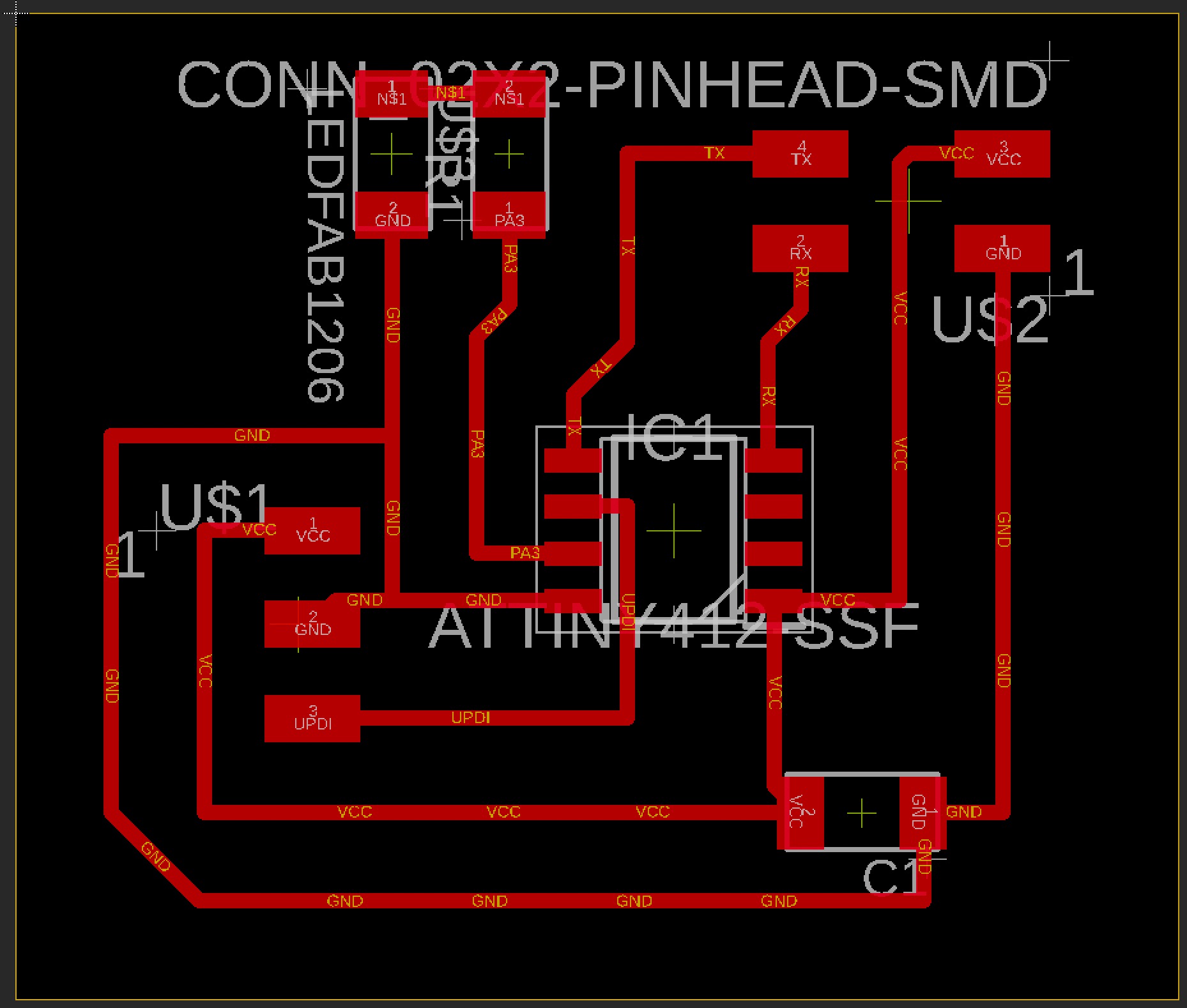
Designing the Boards
There are two boards to design and fabricate. First, is the Bridge board which will communicate out to all the nodes in the circuit. Second, is a node, which will receive messages from the Bridge. To design both the Bridge and Node, I used Adrian’s design as a reference and then drew the schematic and board layout in Eagle.
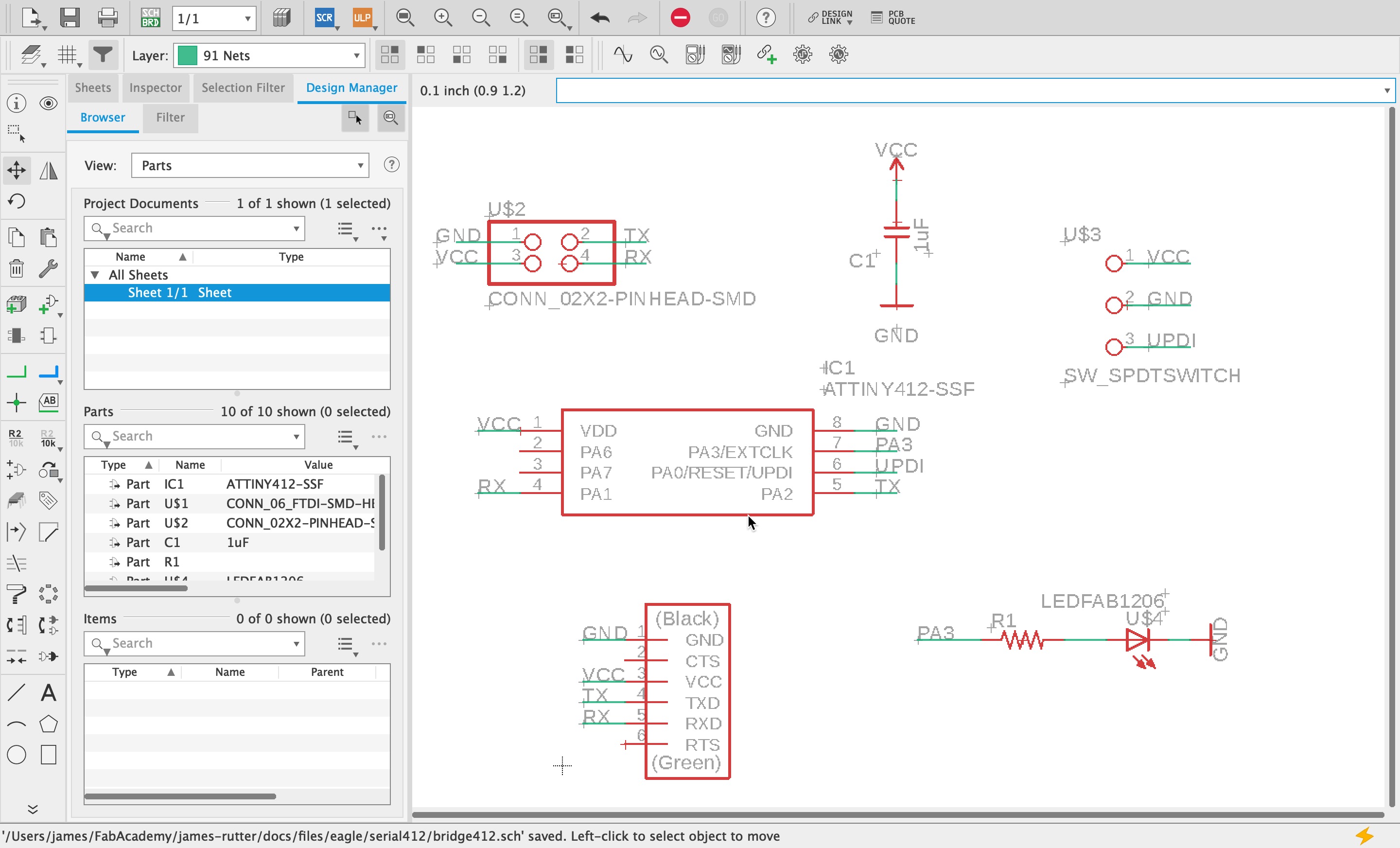
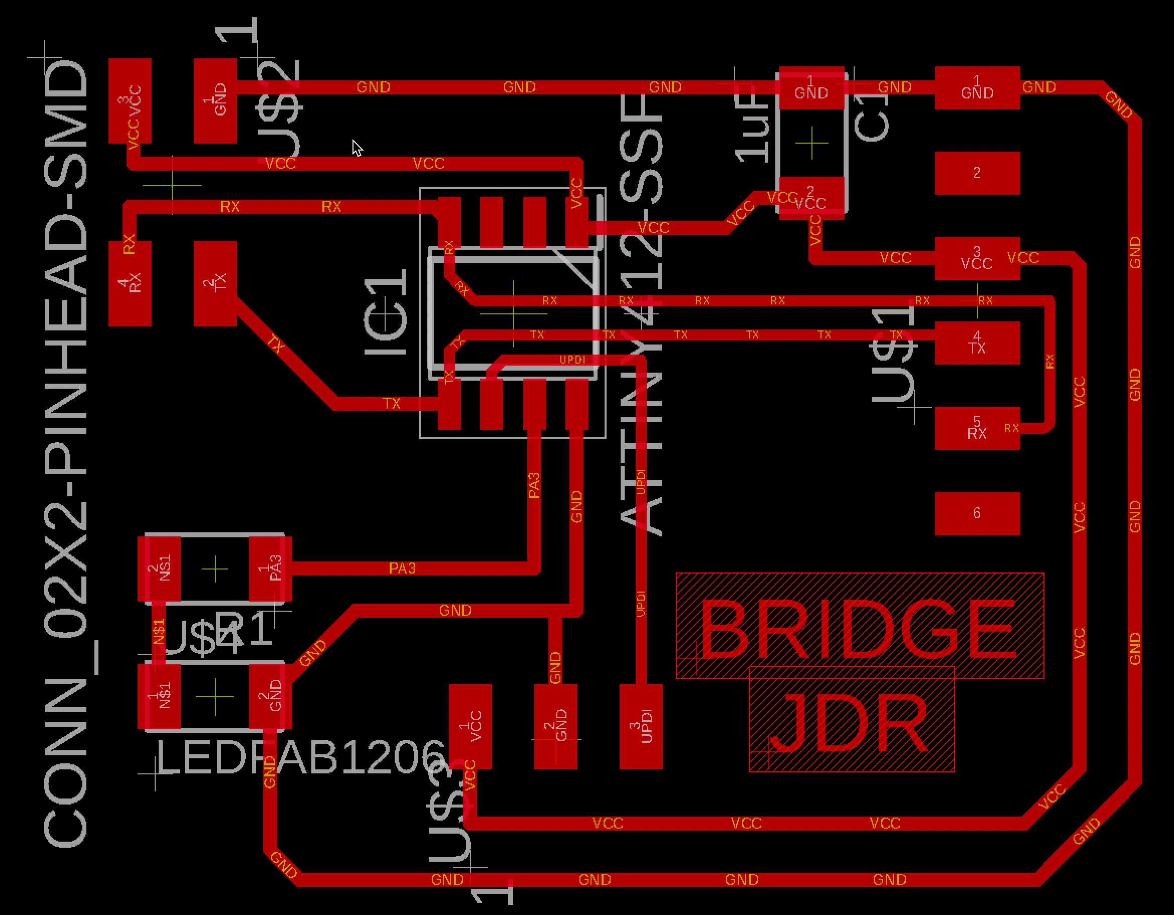
Both board designs are similar. The Bridge design has an additional FTDI header for possible serial communication from the computer (via Arduino Serial Monitor).
Board Design Files
Fabricating the Boards
I milled the two boards (node + bridge) on the Bantam using the legacy software on a dedicated laptop running Windows 10. I would eventually transition to running a virtual machine on my iMac so that I could run the legacy software, but I’ll save that for another note.
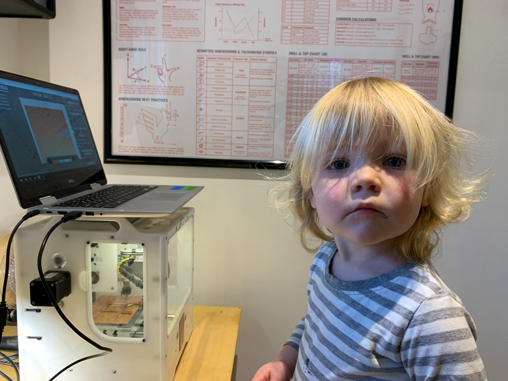
My daughter loves to help hand me the delicate milling tools. So far, I have broken more tools (2) than here (0).
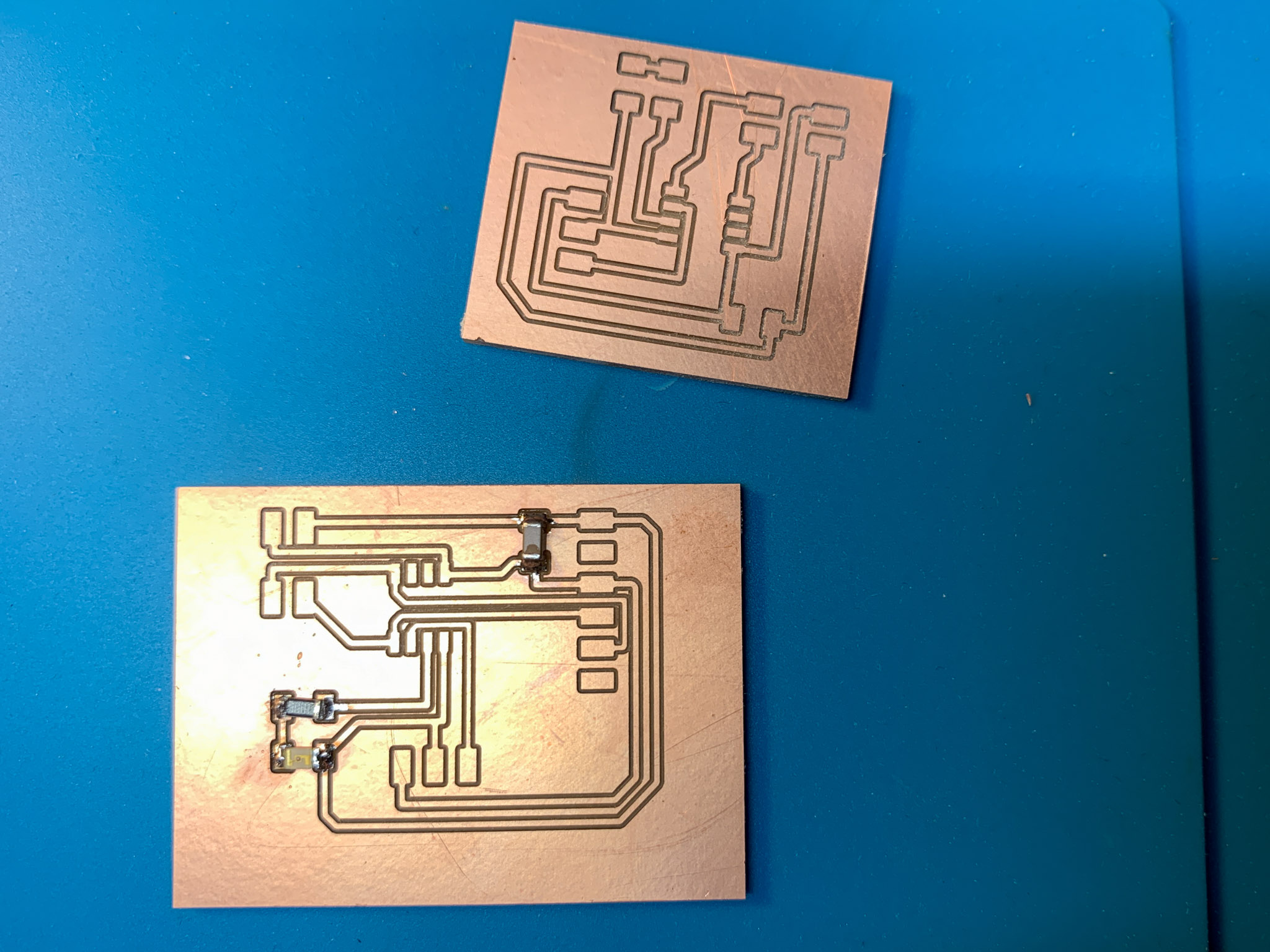
The boards milled out and ready to be stuffed.
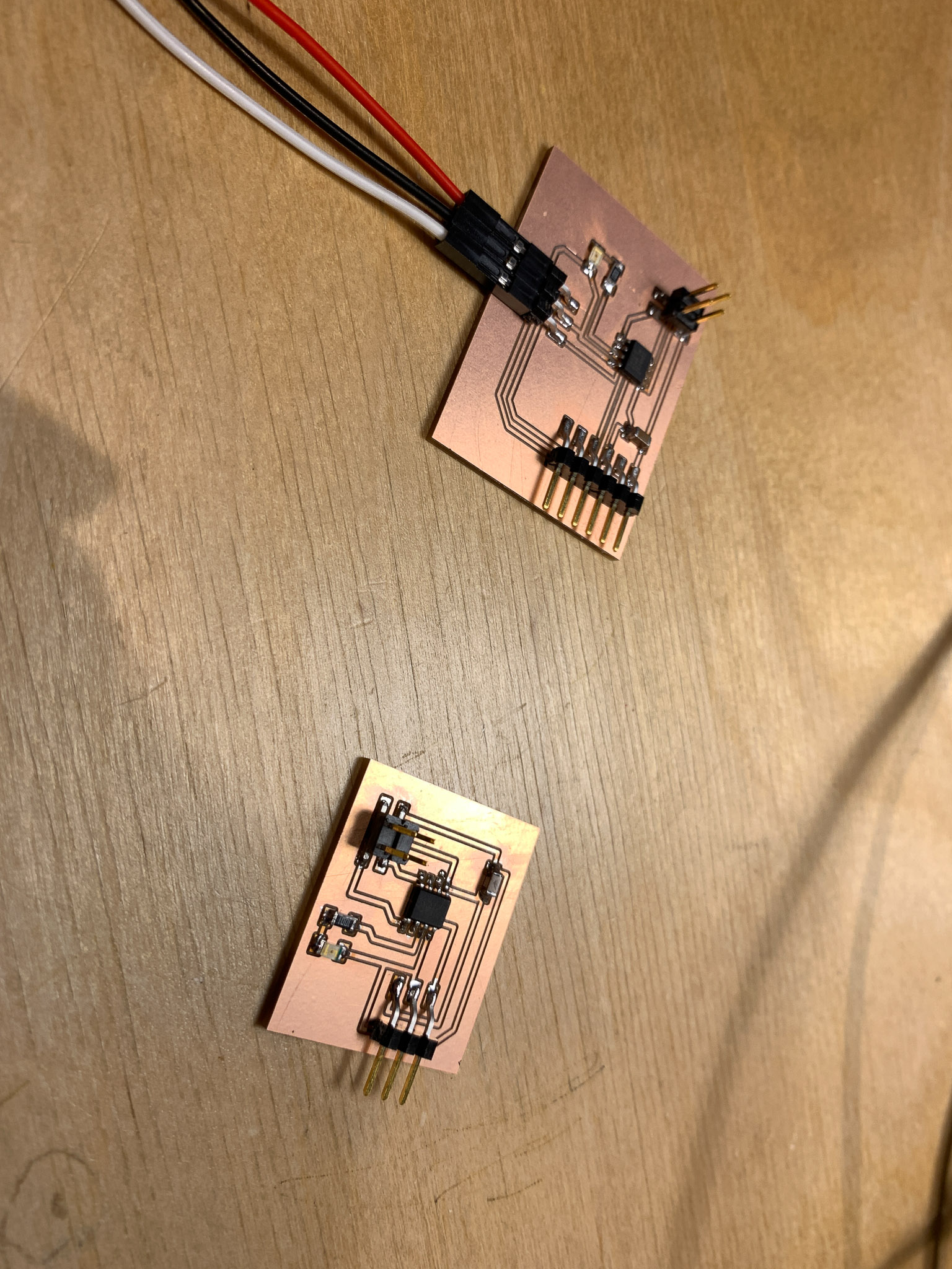
Soldering the Boards
The two boards solder up really quickly because there are only a couple of components. The ATtiny412 simplies the programming overhead, so there is no 2x3 ISP headers.
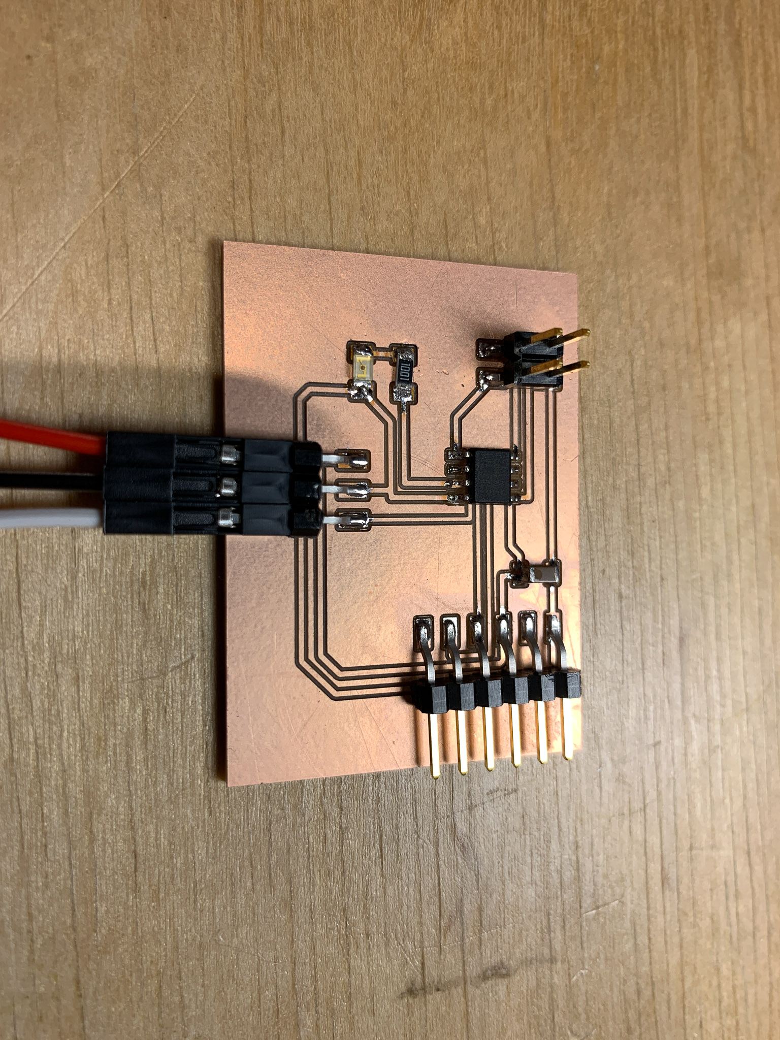
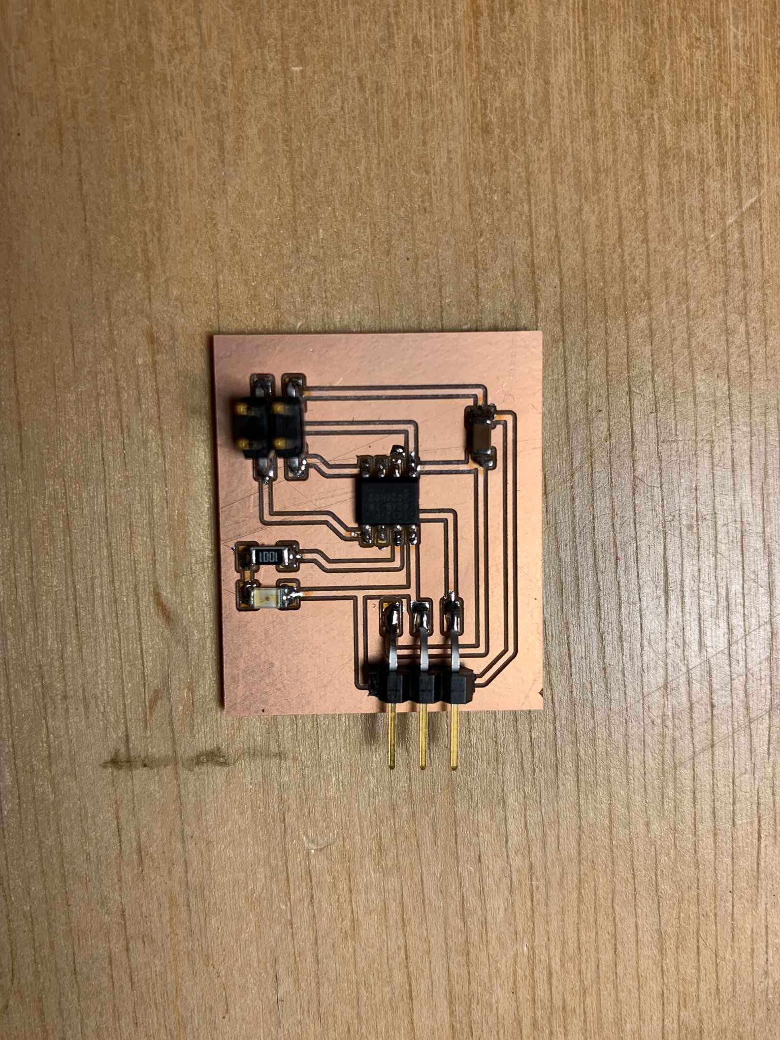
Above are my two boards that I designed and made for this assignment. They came out looking okay. I wish I had made the Bridge board slightly smaller, but it should get the job done.
Programming the Boards
The next step in this process is to program the boards. I referenced Adrian’s Code to develop my own. My process is to reconstruct the code (i.e., type it back out from scratch) to help ensure that I understand what the code is doing.
UPDI
This was my first experiment with using the UPDI programming method on the ATtiny412 boards.
Arduino IDE Settings
In order to program the ATtiny412, you need to use the UPDI protocol. To do this, you need to install the board manager for the megaTinyCore AVR boards.
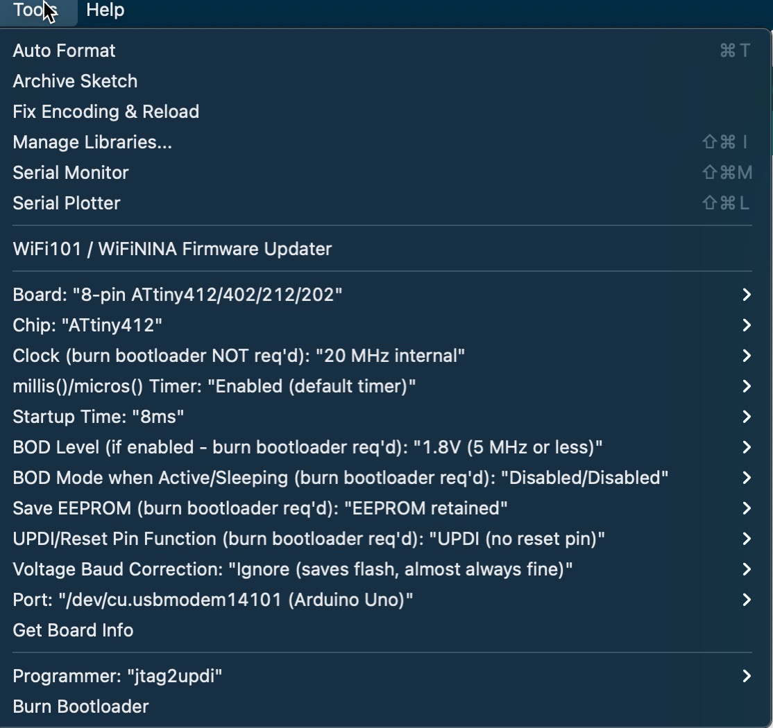
- Chip: ATtiny412
- Port: “/dev/cu.usbmodem14101 (Arduino UNO)”
- Programmer: “jtag2updi”
The above three settings are critical for this to work properly.
Wiring & Connections
Before actually uploading the code, you will need to ensure that the Arduino is properly connected to the destination board (to be programmed). Mostly, this involves connecting the UPDI pin on the destination board to pin 6 on the Arduino.
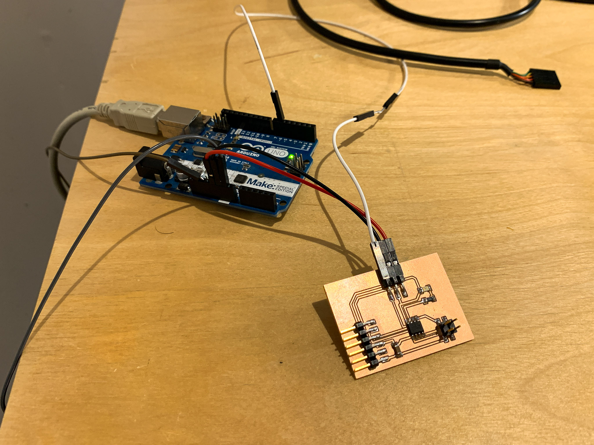
You will also need to plug in POWER and GROUND using the other two cables. In order for the UPDI to work properly, you need a ~5K resistor between Pin 6 and the UPDI pin, and a large capacitor between the RESET and GND pin on the Arduino. Please refer to my UPDI notes for more information on my setup and experimentation with the UPDI and Arduino.
Software Serial on the ATtiny412
The next big step was to get serial communication working on the ATtiny412 board. This took a lot longer than expected because of some confusion over the pin numbering and I actually reversed my TX/RX routes on my board design. Fortuntely, using SoftwareSerial can correct for this error as you get to manually define which pins are to be set as TX and RX.
The above video demonstrates the first initial success I had receiving a message from the Bridge board using the FTDI cable to send a message to the Serial Port on the Arduino.
The above video demonstrates the Bridge code working and communication, indicating that it is waiting to receieve a message from the node board.
Working Network
I finally got the code working after resolving the above Software Serial issues on my board. I was able to get the LED on the node board to blink based on communications sent from the Bridge board. Success!
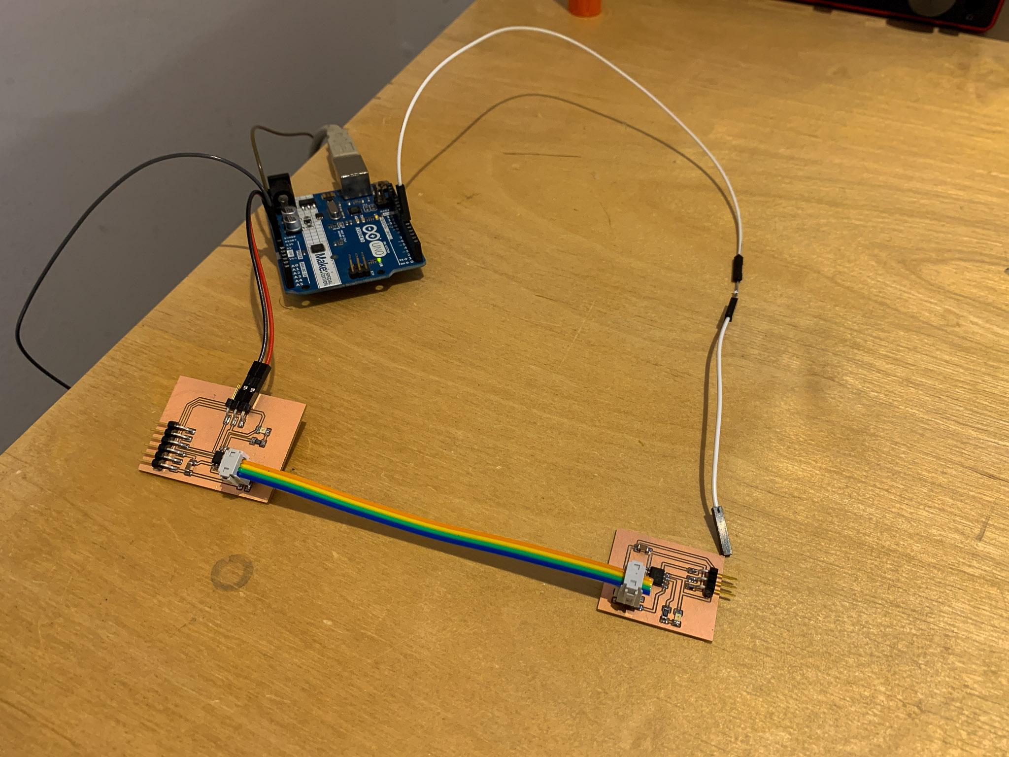
The video below shows the Node board blinking every couple of seconds. Also worth noting that the bus cable I made delivers power to the Node board so only the Bridge board needs to receive external power.