10. Input devices
Group assignment:
- Probe an input device’s analog levels and digital signals
Individual assignment:
- Measure something: add a sensor to a microcontroller board that you have designed and read it
Group assignment
Our group assignment can be found here.
Individual assignment
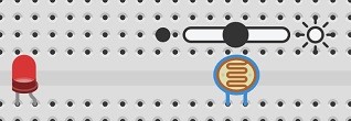
LDR Tinkercad simulation
I simulated the photoresistor connected to Arduino Uno using Tinkercad since I don’t have access to fablab.
STEP 1
I connected breadboard power (+) and ground (-) rails to Arduino 5V and ground. I also extended power and ground rails to their respective buses on the opposite edge of the board which is optional for this circuit but good common practice for future.

STEP 2
Next I plugged the LED into two different breadboard rows so that the negative cathode (LED’s shorter leg) is connected to one leg of a resistor. I changed resistor resistance to 500 ohm. I connected other resistor leg to pin 9.

STEP 3
Next I plugged a photoresistor to my breadbord so its legs plug into two different rows. I connected one photoresistor leg to power and and the other leg to Arduino analog pin A0. I also connected the photoresistor leg connected to A0 with ground using 4.7k ohm resistor.

STEP 4
After setting up my breadboard I started to learn the coding. With the instructions in Tinkercad I was able to write the following code
int sensorValue = 0;

void setup()
{
  pinMode(A0, INPUT);
  Serial.begin(9600);

  pinMode(9, OUTPUT);
}

void loop()
{
  // read the value from the sensor
  sensorValue = analogRead(A0);
  // print the sensor reading to know its range
  Serial.println(sensorValue);

 // map the sensor reading to a range for the LED
  analogWrite(9, map(sensorValue, 0, 1023, 0, 255));
  delay(100); // Wait for 100 millisecond(s)
}
int variable was created to store the current value read from the potentiometer.
Inside the setup, pins are configured using the pinMode(). Pin A0
is configured as an input, so we can “listen” to the electrical state of the potentiometer.
Pin 9 is configured as an output to control the LED. To be able to send message,
the Arduino opens a new serial communication channel with Serial.begin(),
which takes a boud rate argument (what speed to communicate), in this case
9600 bits per second.
In the main loop, a function analogRead checks the state of pin A0 (which will be
a whole number from 0-1023), and stores that value in the variable sensorValue.
Function analogWrite takes two arguments, the pin number (9 in this case) and
the value to write, which should be between 0 and 255. The inline function map()
takes five arguments: the number to evaluate (the ever-changing sensor variabe),
the expected minimum and expected maximum, and the desired minimum and maximum.
The map() function is evaluating the incoming sensorValue, and doing some cross
multiplication to scale the output down from 0-1023 to 0-255. The result is returned
into the second argument of analogWrite(), setting the brightness of the LED
connected to pin 9.
STEP 5
I pressed start simulation to check if the board was working. When I dragged the brightness slider to adjust the simulated light input the led turned off, which means that the board is working.

Final project input
I have an ultrasonic distance sensor which I’m going to use as an input. The data received from distance
sensor is used to control neopixel strip (output) in my final project.
Duration that ultrasonic signal takes to reflect from object
is changed to distance: distance= duration*0.034/2. Equation gives distance in centimeters, value 0.034 cm/µs is speed of sound in air.
In analog to digital conversion following steps are performed:
-
Sampling: continuous time signal to a discrete time signal
-
Quantization: mapping a large set of input values to a (countable) smaller set
-
Encoding: each value is converted to its binary format
I’m desining my board based on Arduino board. First, I tested ultrasonic - neopixel wiring and code with Tinkercad.
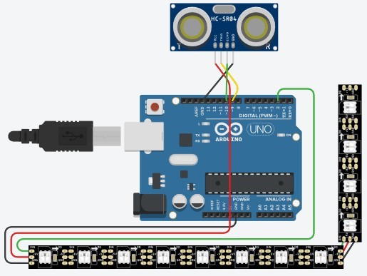
I designed the system by combining neopixel and ultrasonic starter demos.
I used a Ultrasonic Sensor HC-SR04 and Arduino Tutorial example code to control the sensor and to see the distance it detects.
// defines pins numbers

const int trigPin = 9;
const int echoPin = 10;

// defines variables
long duration;
int distance;

void setup()
{
    pinMode(trigPin, OUTPUT); // Sets the trigPin as an Output
    pinMode(echoPin, INPUT); // Sets the echoPin as an Input
    Serial.begin(9600); // Starts the serial communication
}

void loop()
{
// Clears the trigPin
digitalWrite(trigPin, LOW);
delayMicroseconds(2);

// Sets the trigPin on HIGH state for 10 micro seconds
digitalWrite(trigPin, HIGH);
delayMicroseconds(10);
digitalWrite(trigPin, LOW);

// Reads the echoPin, returns the sound wave travel time in microseconds
duration = pulseIn(echoPin, HIGH);
/
/ Calculating the distance
distance= duration*0.034/2;

// Prints the distance on the Serial Monitor
Serial.print("Distance: ");
Serial.println(distance);
}
This code is combined with Tinkercad neopixel starter simulation code to make the whole final project code.
I checked from serial monitor that the code works and it sure did.

When combining the ultrasonic distance sensor with neopixel, I have to map sensor values to be able to control the led strip colour based on the distance.
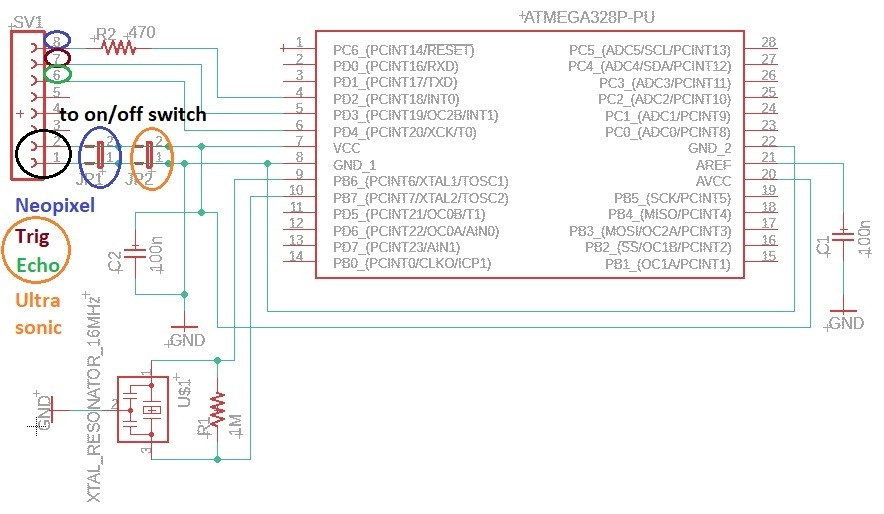
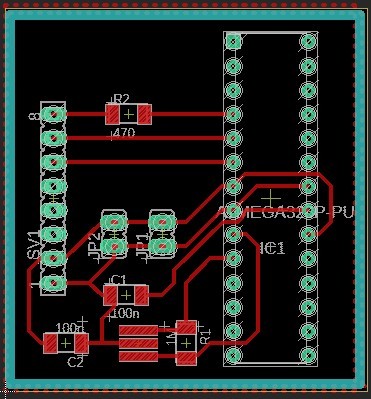
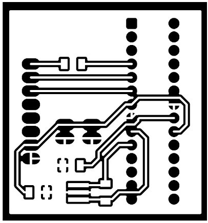
Board design (input+output)
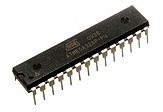
I designed the actual board (input+output) based on Arduino board with help of an article about Understanding Arduino UNO Hardware Design. I am using a ATmega328P in 28-pin narrow dual in-line package since we have those in our lab and I can use my Arduino to program the microcontroller.
I used article’s microcontroller schematics picture to make my own simplified schematic (input and output on the same board). I downloaded ATMEGA328P-PU - Microchip PCB Footprints and Schematic Symbols and added it to my Eagle library. I used my electronics design page documentation to remind me how to do schematics and board design in Eagle.
The components I used are
-
ATMEGA328P-PU
-
28 pin spring strain
-
XTAL_RESONATOR_16MHz
-
Resistor 1 MΩ
-
Resistor 470 Ω
-
2 x 100 nF
-
8 pin connector
-
2 x 2 pin jumper
I ended up with board like this:
I exported png images of the board same way as in the electronicsdesign week.
The board should work the same way as my Arduino board. The board is powered so that the 8 pin connector is going to be connected to on/off switch with wires and the switch is connected to power jack. Both on/off switch and power jack have their place in the lamp stand.
Milling, coding, testing
Explained in output week 12, where I’m demonstrating the ultrasonic sensor use with neopixel on my own board.