18. Wildcard week
Design and produce something with a digital fabrication process (incorporating computer-aided design and manufacturing) not covered in another assignment, documenting the requirements that your assignment meets, and including everything necessary to reproduce it.
Research
The possibilities for the WildCard assignment included the ones I explored - specifically in robotics (3D printing possibilities), machines (waterjet cutter) and molding & casting (vacuum forming).
Vacuum Forming
Vacuum Forming is a thermoforming process, where a sheet of plastic is heated to a forming temperature and stretched against a mold and formed into objects as well as common applications such as product packaging.

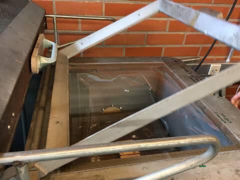
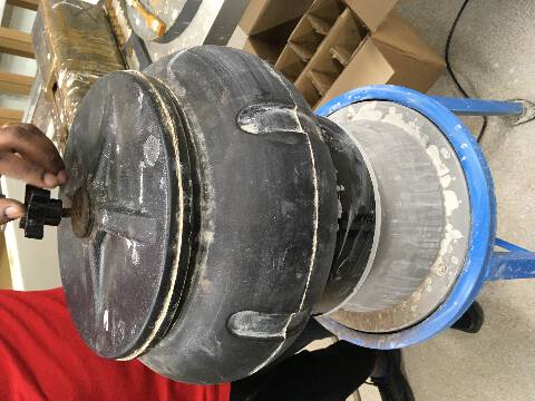
The vacuum forming machine at the FabLab was a very vintage looking rusty Parnavac. Trying to google this Parnavac only spews forth hard, cold, blue-collar industrial complexes. Which is actually their website!
Essentially its operations were to power ON and turn on the compressor for the vacuum.
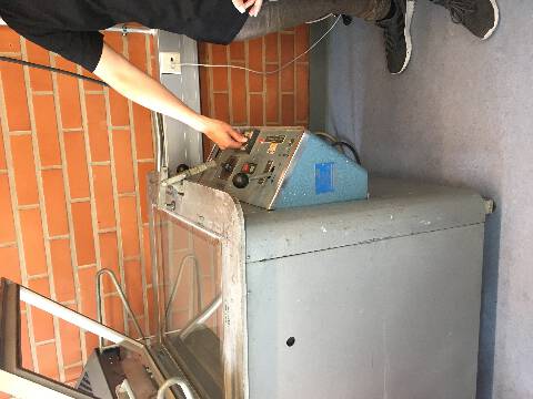
The “user interface” resembled a steam engine cockpit - and perhaps some World War 1 tanks.
Essentially, the levers on the left and right are for bringing the table down and turning vacuum on and off.
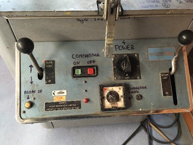
One turns the vacuum on, and then closes the heating lid and locks the clamp in place.
After that one needs to pre-heat the machine for 5-10 minutes. And then the mold object is placed on the table which is lowered with a lever.
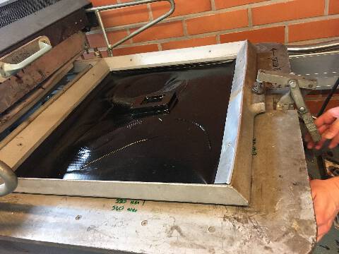
Apparently, one should watch the material periodically to stop the material from bulging - and use the vacuum handle 3-4 times to till the material starts getting “melty” and wavy rippled form on the plastic surface.
A strange problem during this process, is having to “see”
what is really going on

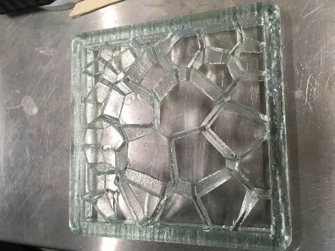
The test piece mold with vacuum forming plastic mold bulging up.
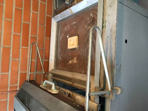
Once the form is established without too much significant gaps, one can lift the table up.
In our first trial, we needed to alternative the “blow up” button with the Vacuum handle several times in order to get the mold to shape in a proper way - as there is no indicator for the temperature or pressure yet - in this sense it is seems to be a “going by the feel” machine thus far.
The sheet material can get very hot - once they are removed, the material is stuck very much to the mold. Apparently the mold in such cases do get a slight angle of three degree or so at the base to allow for a smoother removal.
WaterJet Cutter
The WaterJet cutter is an advanced industrial tool that uses an extremely high-pressure jet of water for cutting a wide variety of materials. To my surprise, use of high-pressure water for erosion dates apparently far back to the mid-1800s with hydraulic mining.

There were a number of very interesting outcomes - both artistic and utilitarian from the jet cutter across a variety of materials, from ceramics, mild to hard steel, metal composites, Bone porcelain to Reindeer Bones (Finland!).
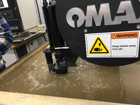
The water jet cutter can cut with a 59 degrees taper. Depending on the material used, The Piercing points might be critical when cutting something fragile. Steel parameters can be more carefree.
The user interface was similar to CNC machine - however it works mainly with 2d files for a 3d object.
Omax layout and omax make are the softwares used with the OMAX55100 WATERJET CUTTER.
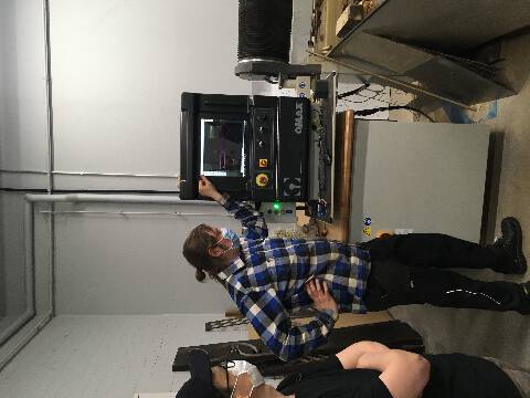
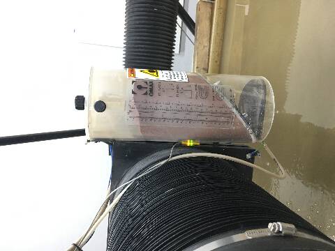
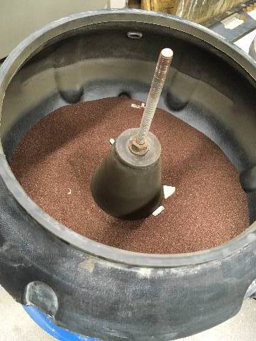
The OMAX cutter rests on a water bed, and the sand pieces for piercing the material are stored in a container.
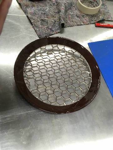
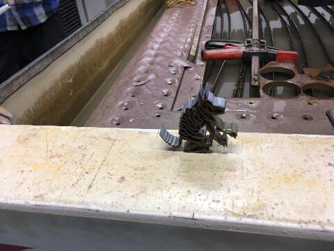
For a test piece, there was a 2 dimensional sketch of a wold we tested to cut out of a leftover piece of metal.
The cut metal wolf is ready!
While such small metal pieces can be sanded with a regular sanding device, the sanding container can be used for other materials such as bone porcelain. Apparently, the sanding process can last for 2-3 days for some materials.
Wild Card Project
I am designing a metal keychain with LEDs for the water jet cutter. The files are in progress and due to Covid restrictions - am in the process of making an appointment with the WATERJET workshop master.
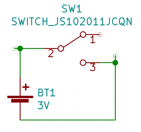
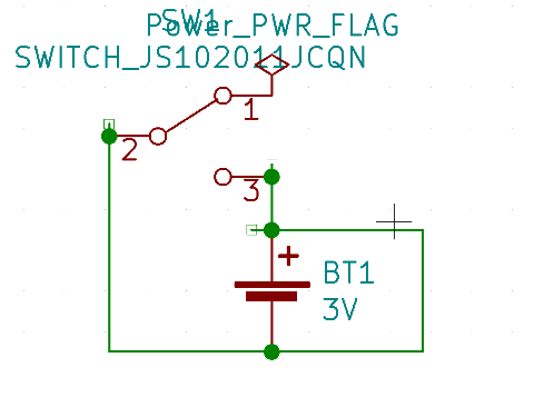
components
- SPDT switch
- cell battery
- LEDs
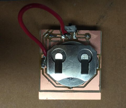
First schematic (fail)
the non working result with a weird edge cut offset :
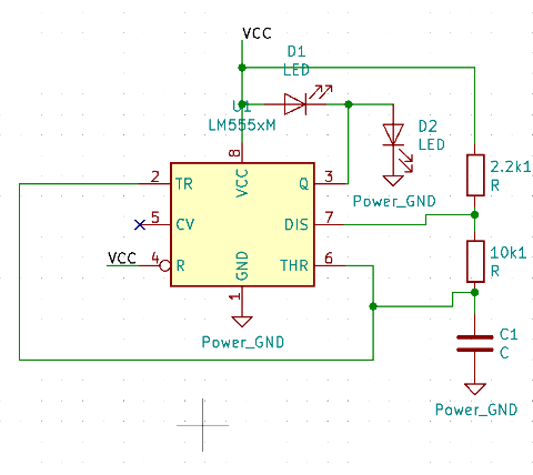
new schematic
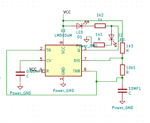
555 timer 2 LED in circuit version 1

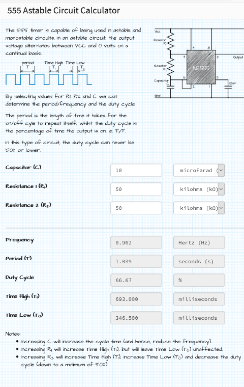
After a bit of math to get the flashing time period T to hover in the 1 second range using an online 555 calculator table as below:
555 timer 1 LED circuit version 2

Coincell with 555 timer from Ranjit Menon on Vimeo.
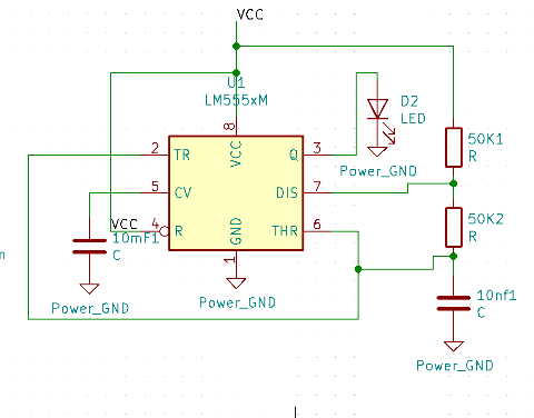
555 timer 2 LED circuit version 3 (to be milled)