10. Input Devices
individual assignment: measure something: add a sensor to a microcontroller board that you have designed and read it group assignment: probe an input device’s analog levels and digital signals
external Sensor experiment
Sensors collect data from the environment. This data turns into information through a change in the flow of electricity from the component. There can be active sensors that need to be charged, as well as passive ones.
Due to the lockdown and lacking my own board, I started out playing with breadboard and loose components I had lying at home - and check if the sensor data generated could somehow affect the ATTINY412 on the HelloBoard as an experiment.
- Use an Arduino and Breadboard to make the connections
- Moving an object in front of the sensor so that the output value is changed
- Read the changes in the value and test different codes
- Programme the ATTINY412 with the real-time sensor inputs
Choice of Sensors
At home under lockdown, I suppose I have to gather whatever residue of home electronics I have from past decade and carry on. Since all robots have sensors, and my imaginary robot friend during lockdown needs that insightful electronic eye, I am going to play with that eye. (p.s. after partial access was open, I did switch eventually to microphone sensor and such that were closed to my final project)
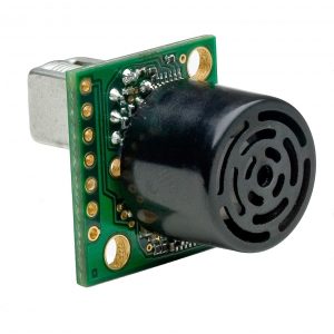
The electronic eye I will be starting with is the Maxbotix Maxsonar - which comes in 7 types depending on the width and purpose of the detection field. In general it is considered an excellent sensor for people detection due it its sensitivity to edges and a high noise tolerance.
Arduino Programming
I basically wanted to start by reading the inputs from the Maxbotix on the Serial Monitor.
Maxbotix had a section on this on their page.
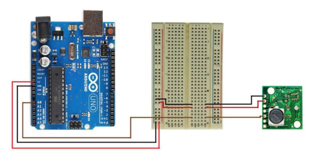
I started with the connections as shown.
The basic code for reading analogue voltage was as shown:
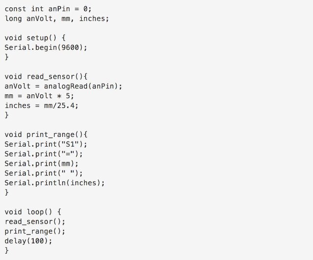
I could adjust the serial range and the delay between the sensor values by looking at the output generated on the Serial Monitor.

The range of the sensor was between 25 and 765 cm - and seemed to have a wide enough detection field. I used a flat surfaced book as a tool to change the sensor values. However I could choose the distance manipulation by mapping the analogue input from the sensor to the range adjustment I wanted it to work as a sensor.
Maxbotix proximity sensor from Ranjit Menon on Vimeo.
By shifting the delay and the range parameters I could test different sensor behaviours.
re-programming the Hello Board led with Maxbotix sensor inputs
I now wanted to manipulate the ATtiny412 led with the sensor inputs. In order to reprogram the ATTINY412 Board LED, I added an LED ON THE Arduino breadboard - for testing the kind of effect I was trying to transfer. I also adjusted the range in which I wanted the sensor to be active.
Since I was going to use the host board to programme the chip, I need a .hex file from my new programme.
On the Arduino side, I tried to define a set of parameters from 1. the arduino, analogue led, sensor side and 2. the correct pin on the ATtiny412.
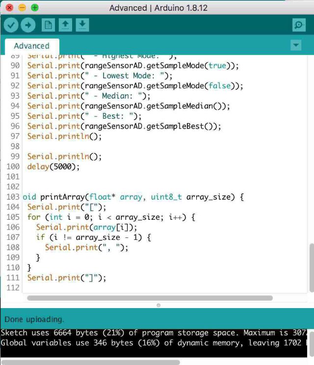
I explored some other range detection parameters on the Arduino IDE.
After getting an output on breadboard LED, I encountered significant issues in trying to transfer the .hex code to the hello.blink board. This is something I am still working on.
This experiment was abruptly stopped, since I wanted to move more in direction of final project - and that would not really have a maxbotic sensor, as its a traditional electronic box.
Next step I tried to programme a basic Arduino with a short mp3 sound sample. A kind of “hello board” for my future mantra box project.
2021 Programming my own board as an Input Device
After I had milled my board I wanted to use the microphone as an audio input device, as well as to get the microcontroller to read audio from an Input Device.
A DAC or a Digital to Analogue convertor is the core component of hardware audio devices. Simple Principle of a DAC is nicely explained in this informative Make Magazine video
Prior to the DAC, we need a signal source - and for this purpose, the main input devices I would like to test is the microphone (preferably surface mounted or at least something as compact).
choice of microphones:
- Electret Microphone
Electret microphones only work when they have a Voltage source.
electret mic circuit Now in input section, we have used an Electret microphone. Electret microphone uses electrostatic capacitor inside a capsule. It is widely used in a tape recorder, phones, mobiles, as well as microphone based headphone, Bluetooth headsets.
An Electrets microphone consists of two power pins, Positive and Ground. We are using Electret microphone from CUI INC. If we see the datasheet we can see the internal connection of the Electret microphone.
An Electret microphone consists of a Capacitor based material which changes the capacitance by the vibration. The capacitance changes the impedance of a Field Effect Transistor or FET. The FET needs to be biased by an external supply source using an external resistor. The RL is the external resistor which is responsible for the gain of the microphone. We used a 10k resistor as RL. We need an additional component, a ceramic capacitor, to block the DC and acquiring the AC audio signal. We used .1uF as our Microphone DC blocking capacitor. The total resistive load inside the electrets microphone is 2.2K.
Electret Microphone Circuit for checking with mic input sources
A pretty inspiring article for DIY mic fundamentals but also how to plan a project with great tips from Nuts & Volts magazine!
Second Cycle 2021
For the new cycle, I decided to re-focus my efforts into getting aspects of my Final Project as close as possible to the input devices and design. Since my final project is an electronic chanting box, it is essentially an “output” device. However, an inpit microphone element would allow people to “customize” and programme their own mantras into the devices as needed.
A list of input mics that are available at the lab were:
- Digital MEMS microphone
- The P48 electret mic made by our team Konch for another project.
ki-cad issues
- hidden pins and the power flag:
- THT (through hole technology) capacitors
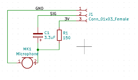
I will be incorporating the above mic schematic that was successfully designed for a parallel project last year, called the P48 circuit for an electret mic.
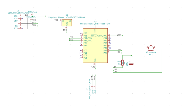
For the input device I choose the following components
- A voltage transformer to step down 5 V to 3.3 V.
- An IC 3216 board for the microphone analogue signals to turn into digital
- FTDI outlet for transferring the digital signals to computer and Arduino IDE.
- UPDI programming pins for programming the 3216 from the Arduino IDE.
- The P48 mic circuit with an electret microphone.
The schematics are as below:
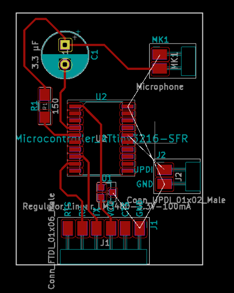
updated some Secrets this year to a smoother Single sided board as follows:
Some “ground rules” to achieve a smoother and less hair-pulling connection process:
- leave ALL the ground connections till the end.
-
Use the ground fill on copper layer method, once all the other components are connected successfully.
-
at this point, run a design rules check - there might be a ground connection that did not connect among the ones left out.
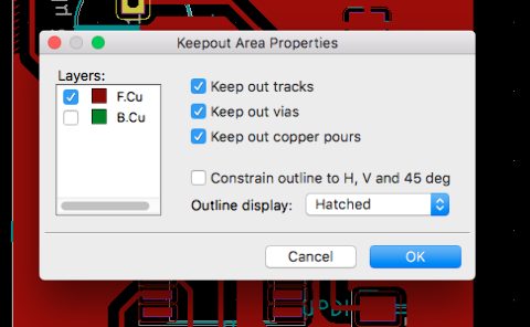 - mark a “keep out” area around the transistor or IC chip so that the ground areas don’t mess up too close to those components - and it is kept clean.
- on the margin layer, make a suitable margin for generating a default outline for the board.
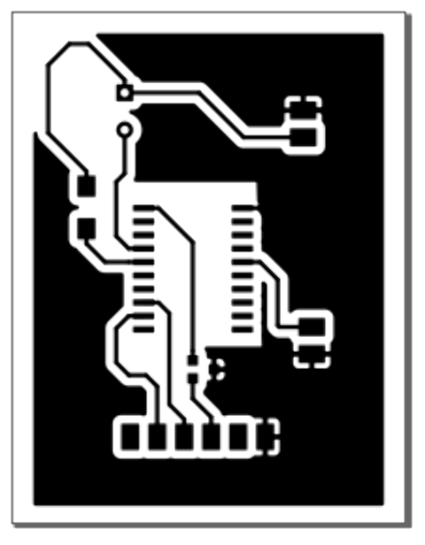
The final pcb layout for milling if below.
after milling
onset of problems!
There was an issue in getting the 3216 to react Neil’s code -
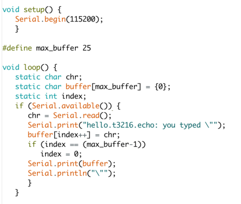
Neil’s 3216 echo code
*============*
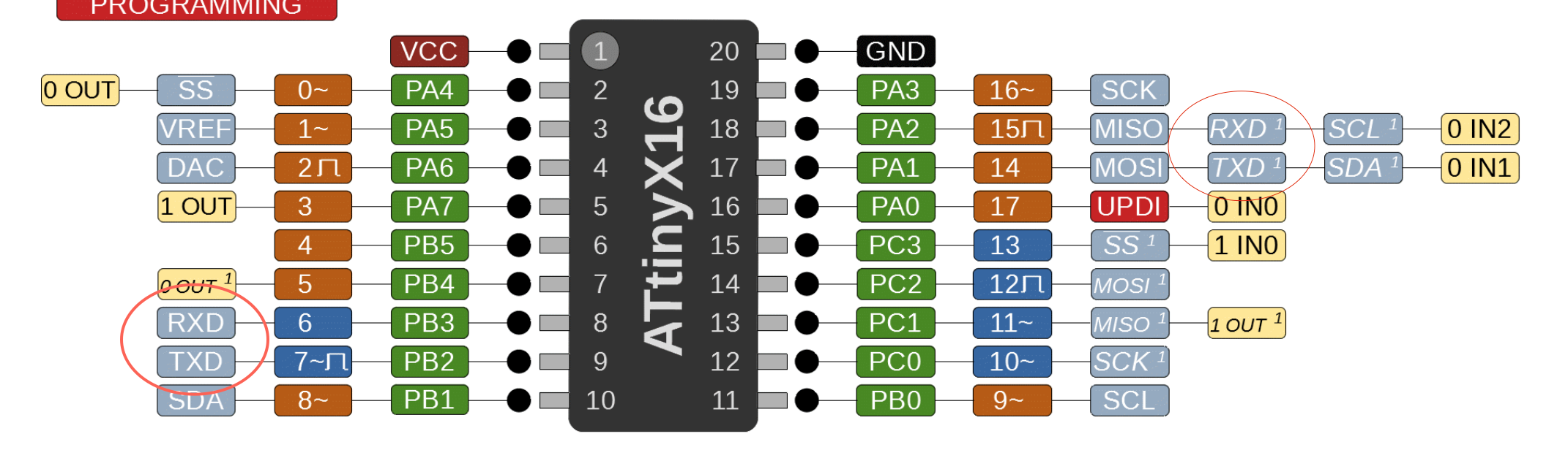
When re-analyzing the schematic I came to a hasty conclusion that RX and TX got flipped! I had to check SpenceKonde page to get Rx and Tx correctly aligned. So its gotta be the jumper?
After interchanging RX and TX with jumper:
however it still did not work
It seemed unfortunately that the RX and TX were correct in the original PCB actually - and the problem was something else!
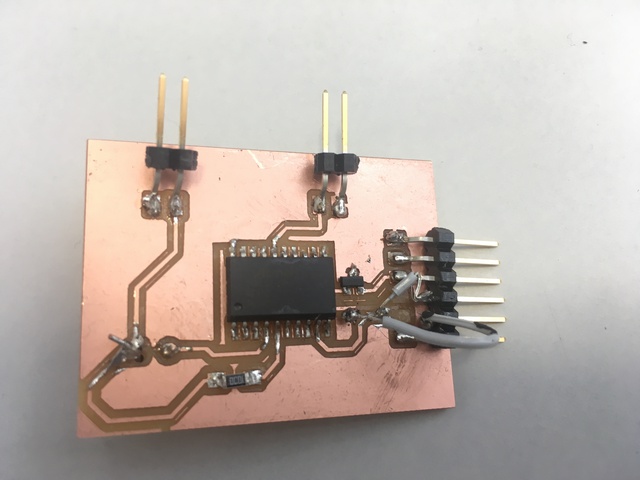
I have to mill this board again and re-solder everything for a retest.
A new board was milled with the correct Tx and Rx configurations.
With the new board, the AtTiny 3216 was successfully echoing with Neil’s code. Now finally one could move onto the microphone measurement via the pin 2 (apparently 2 way DAC).
One needed to code the 3216 ADC to read and print the values - so I started by the basic code:
  int micReading = analogRead(MIC_PIN);
  Serial.println(micReading);
The MIC pin is replaced with the actual mic pin number - which in my case was 2 (PA6 on the 3216).
I started with this code first:
void setup() {
              Serial.begin(9600);
              }


                  int MIC_PIN = 2;


                    void loop() {


                        Serial.read();
                          int micReading = analogRead(MIC_PIN);
                          Serial.println(micReading);

                          Serial.println("\"");

                          }
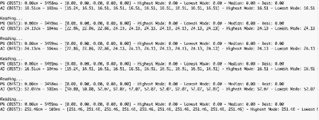
With the above code, I was finally getting an output reading - however it was in zeroes - 0,0,0,0…etc.
I checked with a multimeter the various voltages at key points. All were good except - the voltage regulator converts 5V to 3.3V for the VCC, should have sent around 3.3 V from the PA7 pin output of the 3216. However, I got something in 0.3 V range which was strange.
This was because the PA7 pin should be manually set to high in the code.
set PA7 to output and set it HIGH
pinMode(PA7, OUTPUT);
digitalWrite(PA7, HIGH);
i.e.
pinMode(3, OUTPUT);
digitalWrite(3, HIGH);
I got a huge spike in the readings, in the 1000 range - and barely dipping dynamic range even with knocking the tip of the mic.
At this point I started testing with various resistors from 50 ohms all the way to 20 K ohms. There wasn’t really much difference when it came to the output.
According to Krisjanis, the value when there is relative silence for the mic should be in the middle - like around 500-512 range. This was maxing out the range completely indicated some kind of noise or high voltage or gain at the source.
At this point it is important to mention the 2 mics that were used.
One was the black condenser dot mic for 2.2 K ohm (https://www.cuidevices.com/product/resource/cmc-2242pbl-a.pdf) - and the other was a DIY mic w 2.2k ohm and a 3.3 microFarad capacitor that was successfully tested and used with a sound card for another project.
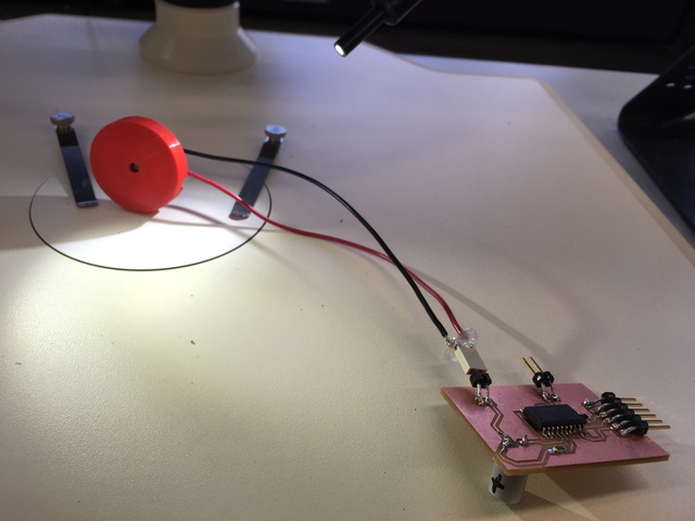
The only way at this stage to get a real understanding of what is happening at the mic end was to run it through an Oscilloscope. That way, one can measure and compare the various mic outputs with an oscilloscope to see the voltage range it outputs.
Time to test the microphones with Oscilloscope!
I am using a GDS-1000 series digital oscilloscope.
its like a camera for electricity. You can use it to debug your device and characterize its performance.
i referred to a helpful video and a very very basic article on audio observation with oscilloscopes.
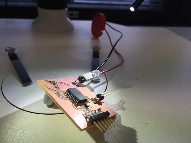
Here I am checking the MAX4466 Microphone Pre-Amp Audio Evaluation Board
3216_4466_mic_preamp_Test from Ranjit Menon on Vimeo.
i connected mic input to the correct pin. On spence konde, number 4 is DAC - and is defined as “2”, so i changed input now to 2.
but still 0 readings. I want to add that even though the schematic has 150 ohm resistor i didnt find one SMD w that value so i settled for 100 OHM. still the values were low.
however, while checking values w multimeter all the values were ok except one that should send 3.3 V from pin 5 (PA7) is fluctuating like crazy
via PA7 to resistor and mic plus, but .. the value dips down to 0.3V - and the issue was that one should set PA7 to output and set it HIGH pinMode(PA7, OUTPUT); digitalWrite(PA7, HIGH)
hence huge spike in the mic readings - instead of 40, starts at 1000 + however the dynamic range hardly shifts much if i knock it, like comes down to 970ish if i tap it.
Apparently, acc to Krisjanis the mic input value with no sound should read as 512 or so (so, 1.5V or 1.6V approx) - and then when the membrane moves, the value fluctuates and goes to 1023 to one extreme and 0 to the other Or 3.3V on one exteme and 0 on the other in analog values. It was time to check the response of the mic with various resistors to vary the voltage sensitivity.
After this I checked a range of resistor values from 10K all the way down to 100 ohms. I wondered if PA6 should be set to high, but it is used as a reading pin so PA6 should be low.
- Trying out a readymade mic with preamp Adafruit : Electret Microphone Amplifier - MAX4466 with Adjustable Gain
a 20-20KHz presoldered electret microphone - use the Maxim MAX4466, an op-amp with excellent power supply noise rejection. It voice changers, audio recording/sampling, and audio-reactive projects that use FFT - small trimmer pot to adjust the gain - set the gain from 25x to 125x. That’s down to be about 200mVpp (for normal speaking volume about 6” away) which is good for attaching to something that expects ‘line level’ input without clipping, or up to about 1Vpp, ideal for reading from a microcontroller ADC. The output is rail-to-rail so if the sounds gets loud, the output can go up to 5Vpp!
Using it is simple: connect GND to ground, VCC to 2.4-5VDC. For the best performance, use the “quietest” supply available (on an Arduino, this would be the 3.3V supply). The audio waveform will come out of the OUT pin. The output will have a DC bias of VCC/2 so when its perfectly quiet, the voltage will be a steady VCC/2 volts (it is DC coupled). If the audio equipment you’re using requires AC coupled audio, place a 100uF capacitor between the output pin and the input of your device. If you’re connecting to an audio amplifier that has differential inputs or includes decoupling capacitors, the 100uF cap is not required.
The output pin is not designed to drive speakers or anything but the smallest in-ear headphones.
ways to make a prototyping arrangement
I felt the need to simulate and improvise the parts and sensors before going back to the schematics. Multiple mics and audio components might need to be tested - which might have additional THT components that affect the sound.
Hence, with breadboard as part of the testing, one could begin to arrange a testbed for mics and speakers.
I referred to certainarticles on making a resilient breadboard connection.
extra Links
next step is to get a basic graph plotter either via Python or Processing to display what the Oscilloscope displays - and this way connect to the Arduino serial port and interpret the values coming from there.