Computer Controlled Cutting
This week was dedicated to explore Computer Controlled Cutting. During Neil’s lecture we were exposed to a number of interesting innovations in Computer Controlled Cutting tools - primarily the Lazer Cutter and the Vinyl Cutter. The assignement for this week predominantly makes use of these two tools.
Group assignment:
    1. Characterize your lasercutter's focus, power, speed, rate, kerf, and joint clearance
    2. Document your work (individually or in group)

Individual assignments
    1. Design, lasercut, and document a parametric press-fit construction kit, which can be assembled in multiple ways. Account for the lasercutter kerf.
    2. cut something on the vinylcutter
Group Assignment
The group assignment was about characterising the LaserCutter - adjusting the Laser Cutter’s focus, power, speed, rate, kerf, and joint clearance.
The group assignement was done with fellow academicians Solomon and Kitija, and links up here:
The individual assignment was:
A. design, lasercut, and document a parametric construction kit.
B. design and document the use of Vinyl Cutter.
Lazer Cutting
- Lazer cutting and documentation of a parametric construction kit using a CAD software.
My Final project is an Audio Box and a casing that would represent the inner qualities and heritage of the content, ie mantras. Indian art has been since ancient times been strongly metaphysical - and sacred geometries and architecture has been part of its culture. I would like to continue to explore the lazer cutter to see how to get a lot of interesting patterns in this way.
For lazer, I have been inspired by wanting to create an object related to Indian aesthetic tradition. One of those motifs are the kind of patterns that adorn the intricate stone walls and surfaces in temples.
For the assignment I explored both Fusion 360 and FreeCad, however I was introduced to this software called Cuttle - a tool being developed by a colleague who was one of the main programmers at Webflow. It is designed for Lazer & Vinyl, and I started exploring its capabilities.
Thinking outside the…BOX
For press-fit construction, I went through Fab Academy’s helpfullinks.
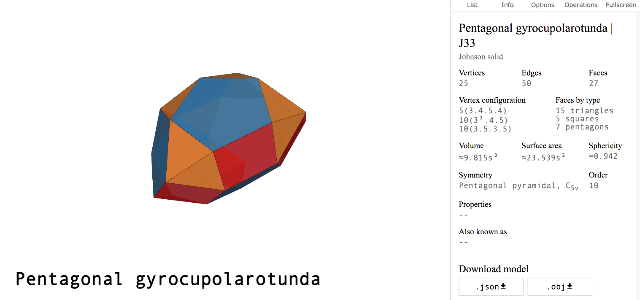
My initial ambition levels were to make a polyhedra structure, with angles and the joineries as needed - it was hard not to get inspired by polyhydra examples.
However as soon as one starts thinking about the angles on a polyhedra structure, the humbling factor steps in. Dihedral angle - Wikipedia
(At least learnt a cool new word from that wiki link StereoChemistry )
The angle calculations look complex trigonometry.
Anyhow, I feel I need more gyrocupolarotunda in my life once my parametric skills are upto par with calculating the math and applying it to the software. The website Polyhedra exports in JSON and OBJ formats - and the subsequent data could be used to calculate the angles for the joineries. I will someday in the future return to Polyhedra once I acquire new lefty neurons in my largely right-brained constitution.
While browsing for potential joineries I came across two interesting resources - one was an old Japanese book on Joineries & Woodwork as a scanned PDF. As well as a poster reference on 50 digital joints. These were some incredible timeless craftsmanship that made me think, are these achievable with a machine - and if they are then what are given the challenges of our times as limitations in software in contours?
I also began benchmarking some previous years projects in the process, and found lots of nice examples from Charlotte Latin.
Parametric Design 1. Thinking inside the BOX - using Cuttle software for a parametric box
After attempting some geometric forms with Cuttle, in order to learn Cuttle workflow I decided to start with a box.
The box is a fairly basic design, but through this exercise got my hands on experience with this interesting new software and the subtle tyrannies of parametric details.
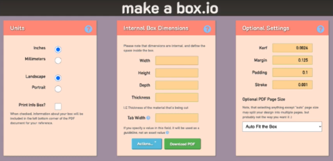
Of course, Boxes are the easiest of parametric designs, partly because there are scores of ready downloadable files in Illustrator and other flat vector formats - and also BoxMaking online softwares where you input the dimensions and Kerf and you just get the ready vector file that you then import to your Lazer Cutter.
After our Group Assignment - where we explored the power focus and speed of the Lazer Cutter, I wanted to move slowly from there toward a construction kit - and thought a box would be a middle ground to test and fail quickly in some of the processes between the computer and the final lazercut product.
Moreover - Toby from Cuttle had an interesting example that explored the parametric creation from scratch of a Box Maker itself, and not just a ready Box.
This means using the same parametric steps to create any structure from scratch.
Also in the end I would know exactly the different stages of setting up the Parameters in order to move onto more complex Parametric construction kits - and also help me to compare Cuttle, a pretty new software with the industrially heavy counterparts for CAD such as Freecad and Fusion 360.
Using Cuttle
Creation of the Edges
The first steps are thus to make edges, planes and then the box layout.
We basically need 6 surfaces for the box. And we need some finger joints on the edges to have them “join” together.
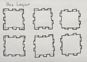
As can be seen, each face is pretty much the same square, the only difference being how the edge tabs are arranged to fit together.
Without planning a sketch it is difficult to know which edge matches which groove.
Set the first edge ie edge A1.
We are making an adaptive design using Cuttle software, meaning the global variables will adapt to whatever changes are needed for the box size.
So we just start out with a decent enough square size - the length being 0.4 and the thickness of 2 mm (0.078 inch).
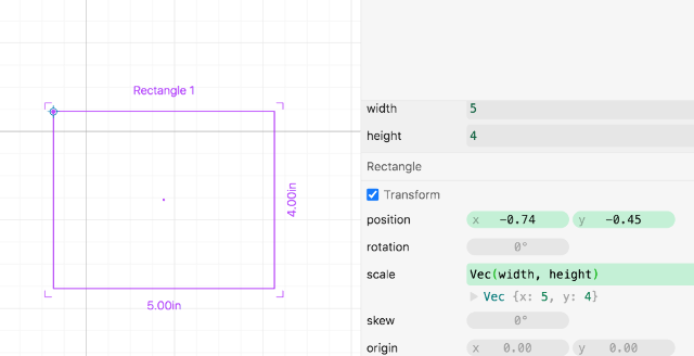
length = 4, material = 0.078 inch, tabSize = 0.5
All objects we create in Cuttle has an anchor point of the origin. In the first instance, we are making the tab for the top left of the rectangle - as a result we move the anchor to the bottom leftmost corner.
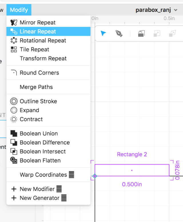
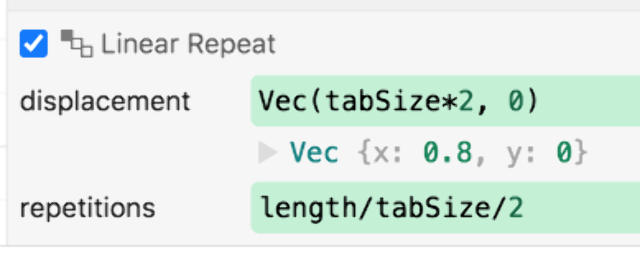
Linear Repeat - displacement & repetitions
Displacement value will be tab size times 2; Vec(tabSize*2, 0)
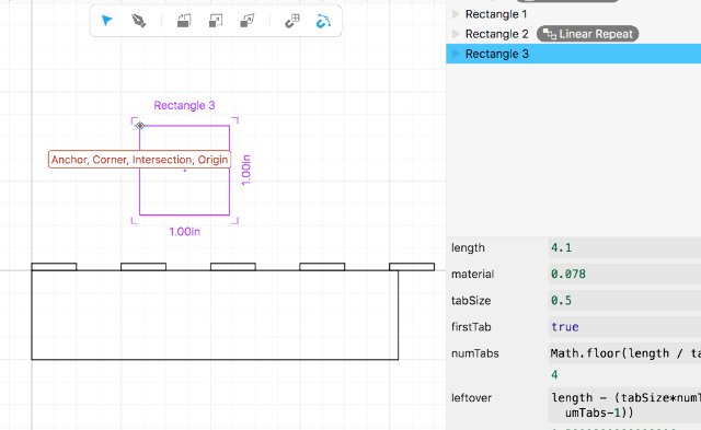
When we spread out the tabs, because of the float values, there is some leftover amount as well as tabs spilling over the edge.
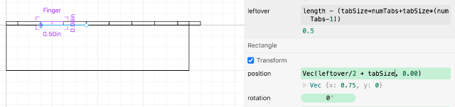
Leftover: length % tabSize (javascript for modular operations)
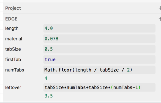
numTabs: Math.floor(length/tabSize/2) to convert the float into integer
If we know the no. of numTabs, then we know the tabSize as well - in which case we can calculate the leftover as (tabSizenumTabs + tabSize(numTabs -1))
Once we move the edge length parameters, we can see that the rest of the variables are being calculated to fill in automatically.
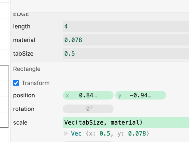
Next is to position and scale the extra fill in tabs. One needs to also add some numbers randomly to see how many tabs might fit more appropriately - and the visual reference helps to “calculate” as well. (ok, looks like they fit, the Reasoning comes later..)
a great way to check if its ok, is to check with different tabSizes and see if they are adapting well..and seems to work.
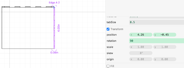
Making the second edge - A2
The second edge is the inverse of the first one, where the tabs go into the spaces of the previous one.
We create a copy of edge A1 and shift the anchor so as to lay it at one side of the box.
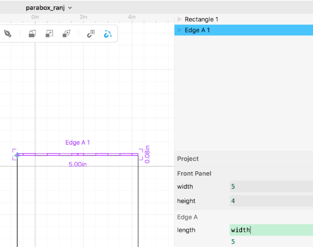
making the Front Panel
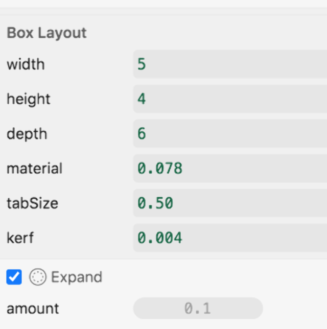
This is the main surface of the rectangle. width : 5 and height: 4
The front panel has all edges as first edge A.
From the final box layout, we need t thread through the material size, width and height through all the other elements so that is adaptive to changes in material and tab size changes.
The front panel has both of the edges 1 and 2, and for the other sides we can use the mirror repeat function.
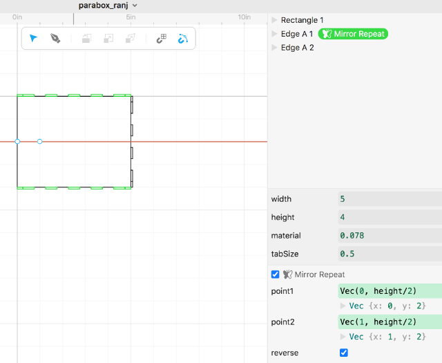
The interesting thing about CUTTLE is that it operates in layers, so once a modification is chosen, it automatically appears as a sub layer within the project - this helps to quickly select the parameters within for instance “mirror repeat”
The parameters in mirror repeat, help us to set the vectors the 2 points along the axis.
To make the 2 points coincide to the center, the values were established as
point 1: Vec(width/2, 0) point 2: Vec(width/2,1)
Additional tiny corner rectangles were used to fill in the open slots left by the edges.This was done in the same way as the previous functions, making the first component and then duplicate the element and set the anchor point depending on where we need to set the origin.
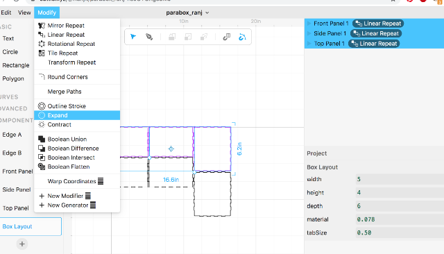
Boolean application
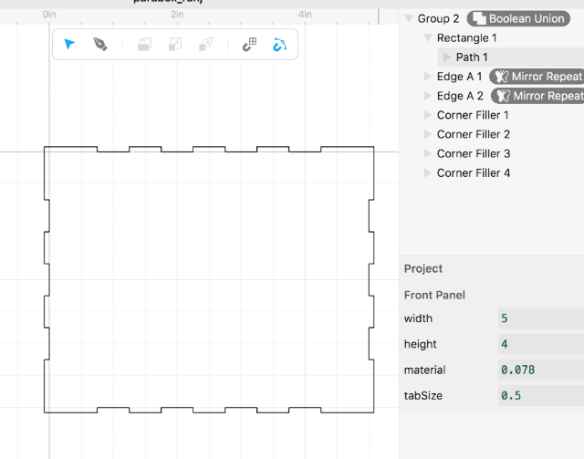
The Boolean function was really great in combining the Front Panel, and the 4 edges we created into the single surface plane - Boolean Union was easily achieved by simply selecting all the sublayers and dragging them to the parent element as needed, creating an instant Boolean.
Side panel
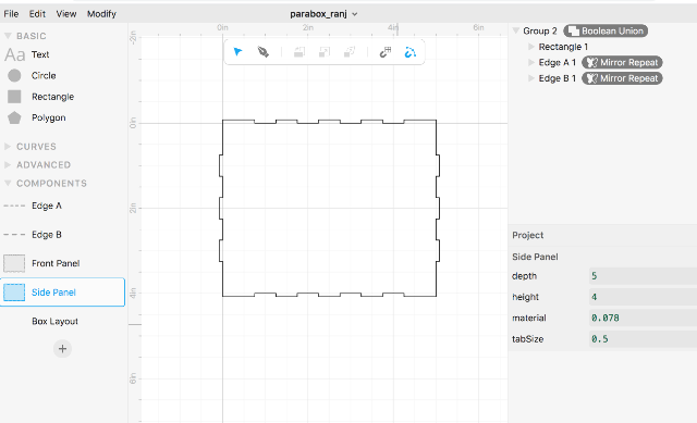
For the side panel, we need to make a different kind of edge.
So for this we make an Edge B series.
By modifying the depth dimensions and the position, we create the required edges for the side panel.
Top panel creation
here, the previous variables for tabSize and material are added.
Box layout creation
Here we drag in the Front, Side and Top panel inside.
here also the values should thread through so the width, material, depth etc. are set to the global variables.
We have one element now of each of the panels and now we need to duplicate them.We choose the linear repetition option to create the other similar parts.
displacement = Vec(0, height+material 3) thus establishing the needed gap between the elements for taking into account the material size (the height+material3 being the X or Y displacement)
Kerf compensation
Choose an expand modifier.
Kerf compensation for a 2mm plywood was measures at 0.11 mm during our group exercise.
After the kerf compensation, the material size, the tab size are adjustable and adapts itself to the changes in the variables.
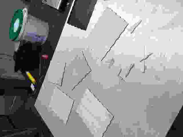
The output SVG was exported to be lazer cut.
- ON to the lazering
The output was taken to the lazer machine and outputed.
With Cuttle one could make your own super personalized custom box maker with this tool.


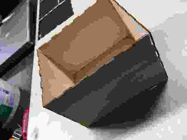
However, the kerf value seemed to have some issue. The joints were loose and the box was not tightly packing together. Upon doing a check on the Cuttle software, it seems that when I had tried to do the “expand” function after setting the Kerf, the edge joints were “eating” into each others space - so they were too close. This happened because I was converting the edge thickness acc to material size and that brought it closer than the example suggested.
Reflections on Cuttle
Constructive solid geometry (CSG; formerly called computational binary solid geometry) is a technique used in solid modelling. Constructive solid geometry allows a modeller to create a complex surface or object by using Boolean operators to combine simpler objects and potentially generating visually complex objects by combining a few primitive ones. This is what Cuttle seems to excel at in terms of interface design.
Cuttle’s flow seemed incredibly smooth, however being new to parametric modeling - I could not put my head around many of the math functions being used. I would like to see if more complex shapes and a parametric construction kit with polyhedral structure are possible - however would need to check with Fusion 360 next (as was original plan before Cuttling along)!
The parametric flexibility was really good, and the ability to thread through the variables through all layers of the components made the design very flexible.
One needs to get used to math operators and needs to use a lot of reasoning and logic, in order to use it. On the other hand, using some of the mirror abilities gives one instant interesting patterns for Vinyl cutting.
However, being still under Beta mode, there is a lot of changes expected in the software.
[edit: I “advertised” Cuttle during neil’s lecture and the phenomenal Nadieh Bremer picked it up - She used Cuttle in a way not even their creators imagined it!]
Parametric Design 2. Parametric Construction Kit using Fusion 360
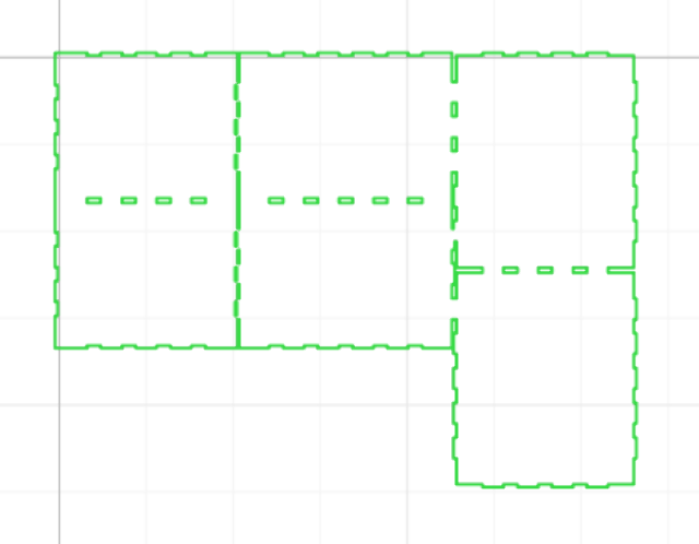
I sketched a basic 2-shape parametric component design that would use a square shape with a curved element.
For me, the most powerful design feature of Fusion 360 is the ability to define Parametric values and alter them anytime - which is then reflected in entire design that has used that variable as a parameter. In fact, I start by creating such cutom “user parameters” in the software, that includes the thickness of the material.
screenshot of parameters
Design of the Square element was pretty much straightforward. I created a sketch of the element and entered the corresponding parameters.
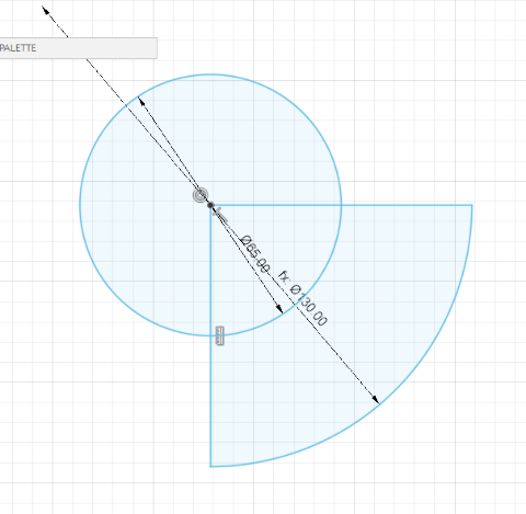
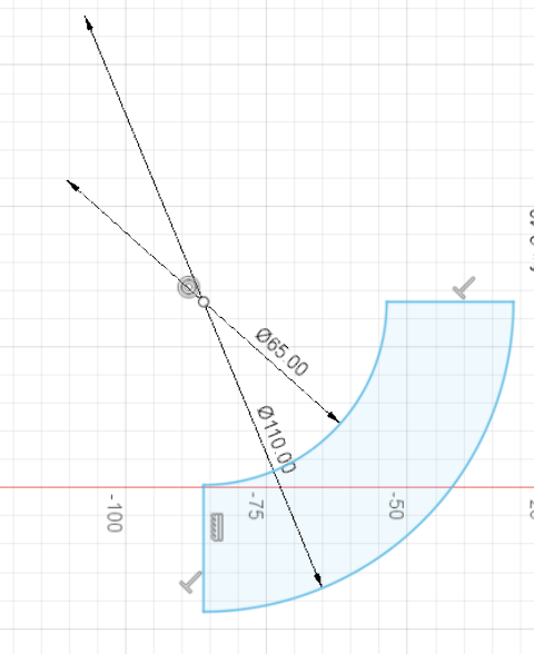
Design of the Circle element involved drawing a circle and then splitting it into 4 quadrants. Once it was split, I saved one of the 4 quadrants and added the same Slot width, depth and section to the quadrant.
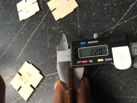
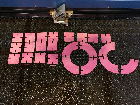
Since the material thickness has been decided at “3 mm “, I go with a 3mm piece of wood that I spray painted with a purple shade. For this, the Properties of the Lazer Cutter for 3mm + plywood are checked and the suitable vector setting is set for cutting.
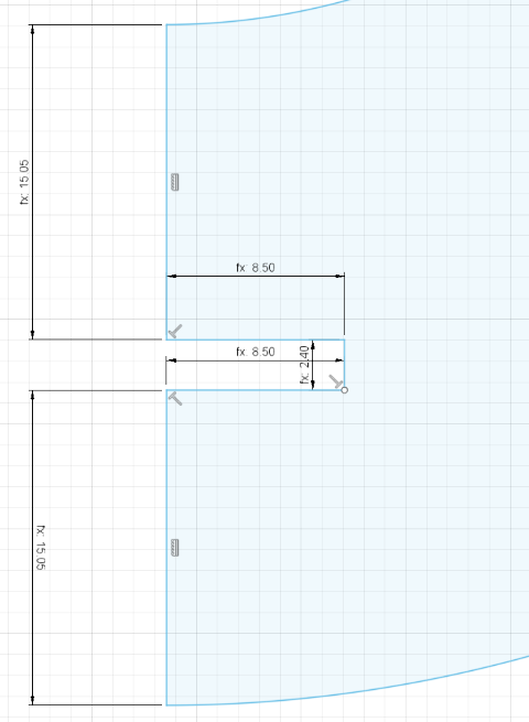
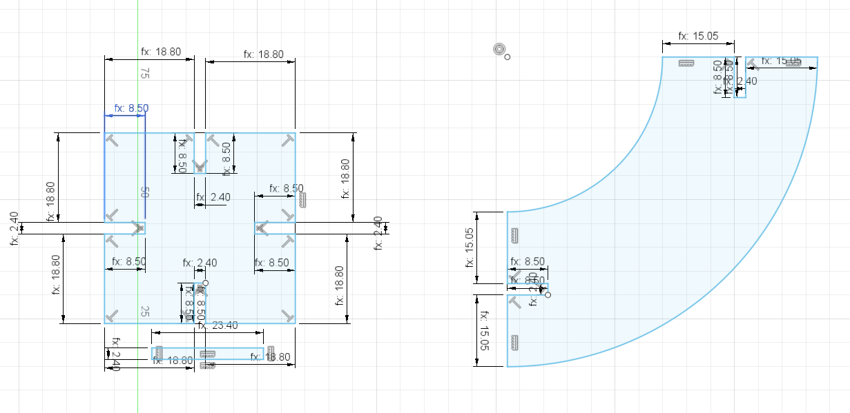
It took several attempts before being able to set the “kerf” value to an appropriate enough size such that the pieces would not just fall off - or just not find a gap large enough to even squeeze. This ideal kerf was later found to be at 0.2 mm - since Fusion 360 is a parametric softare, all one needed to do was change the kerf in the properties. (Modify > Change Parameters command).
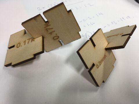
Here is what the final “product” with proper kerf settings looked like as one configuration.
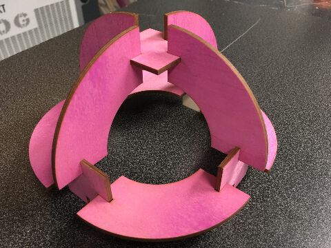
screenshot of circle and square and all-in-one view
Finally, to make the files visible on Coreldraw (Lazer Cutter software) - I needed to export the file from Fusion 360 as .DXF
On the lazer cutter, I select the Outline and ensure that it is converted into Hairline. The properties of the Lazer are then adjusted according to the material I am using
Vinyl cutting
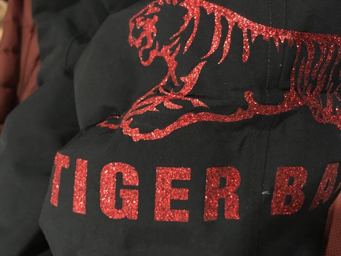
For the Vinyl Cutting exercise, I immediately knew what I wanted. I have been an artist/performer going by several names. And the latest series of Gigs as a DJ mixing both Indian film music and popular dance genres - I went by names like Glowy Red, Ran Jit, Makapav, Trollywood and lately - been wanting to consolidate it all into one name - Tiger Balm.
- I first scanned the internet for interesting packages and Logos of tiger balm. The iconic leaping Tiger and the Chinese letters were perfect - and soon found a high resolution image using the google preferences.
Steps to transferring the Vinyl from internet to jacket
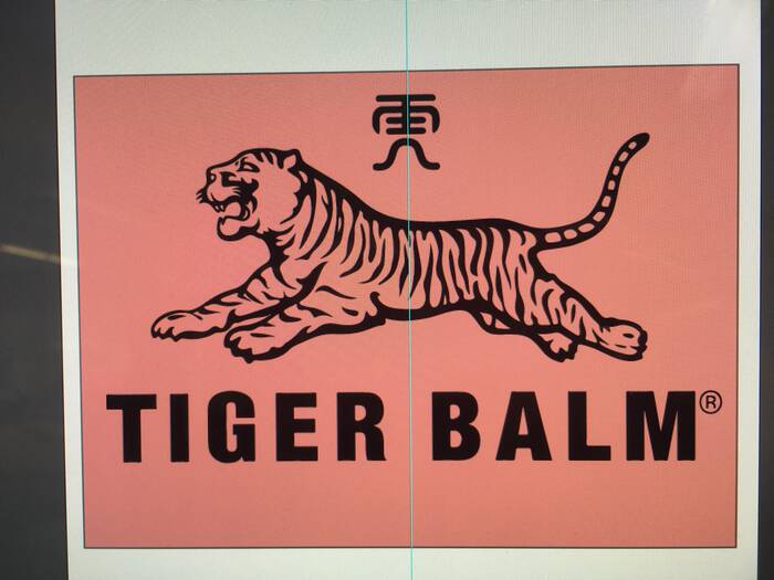
Once I took the Jpeg to Illustrator, I cleaned up the image background - and traced the image into a 3 color vector.
- In the image below, you can see I put it against a Saturated background to check if there are any “artefacts” left behind - to achieve full transparency.
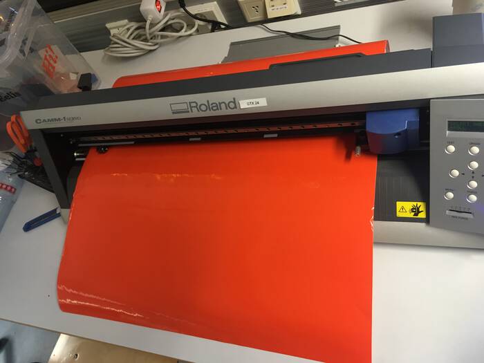
Initially, as a test sticker, I printed it on Glossy Orange Vinyl as a Sticker - rather successfully.
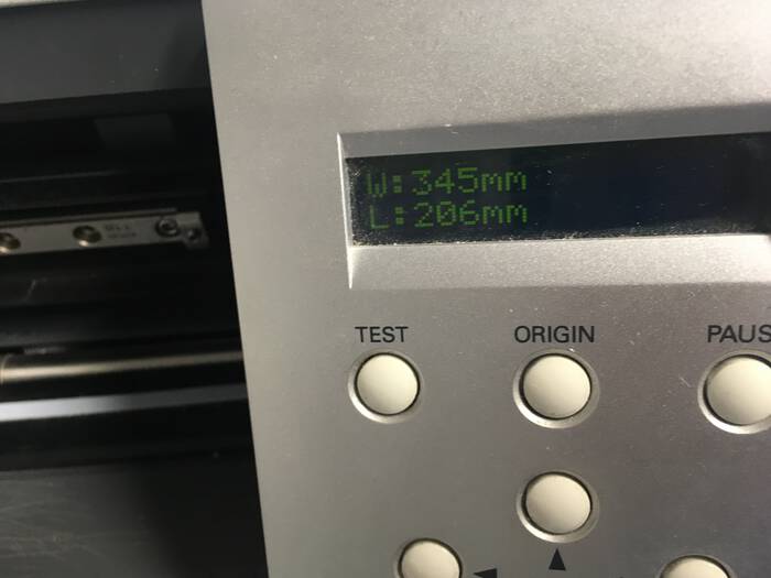
- The Roland GTX 24 was chosen from the FabLab computer prior to sending it to the vinyl cutter. The Sheet was adjusted between the white marks on the Vinyl Cutter - and the work was sent to the machine. It took a few seconds to load up. After fastening the sheet, I let it run go, & the Sticker cut pretty fast.
Before printing, on the Roland GTX 24 interface, it is important to cross check the dimension it interprets - with your own image.
the sticker is printed “as is” on the glossy side as you create a “mirror of a mirror image” unlike the fabric transfer - which is a pure mirror print. Will explain why in next step.
-
After this I moved onto the material I wanted for my jacket transfer.
-
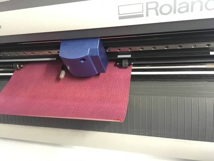
I chose a nice glittery sticker material for the purpose. And did the exact steps as above - except I sent a “mirror” image to the printer because unlike a sticker, the fabric heat transfer happens with a single transfer (from mirrored vinyl direct to fabric) & whereas as a sticker it first transfers to a 3M adhesive sticky sheet (mirror) and then again transferred to surface as normal image.
However, I made a mistake - I mistook the glossy side for the vinyl cutting surface. This is a common mistake. Instead it is the non glossy surface that is printed on, as the “gloss” or actual material is pushing against a “peel away” skin for post transfer.
mistake:
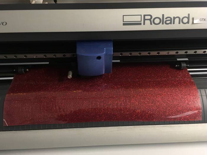
rectified / the correct side:
==================================================================== * Once the prints were ready, the print had to be isolated from its artefacts on a very sticky piece of vinyl transfer. With a special tool that resembles a dental tar remover - I proceeded to clean up the sticker until I was left with the negative original of the transfer.
This is the backside.
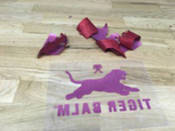
This is the transfer side, with the real material - that sticks to the fabric under the heat transfer.
![]()
We headed to the Costume Department for the heat transfer machine. Since my jacket is made of Polyamide material, I had to research a bit so that there is no fire hazard/damage to equipment/damage to material w a square patch.
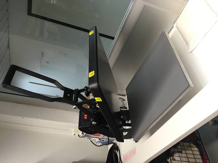
It seemed the temperature tolerance was on the edge (about 145 degrees celcius). As a safety precaution - baking paper was inserted between the fabric and the heat surface. After about 12 seconds, the machine was lifted and the transfer peeled off easily.
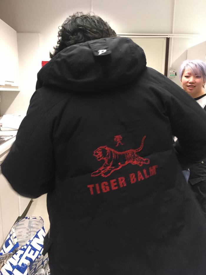
All the details were retained wonderfully! And the glitter material gives a great shine.