Interface and Application Programming
The individual assignment for this week is to write an application that interfaces a user with an input &/or output device that we made.
And the group assignment is to compare as many tool options as possible.
I started by looking at some tutorials that could point me in the right direction, and started by following this one (in french).
For this very first test I used:
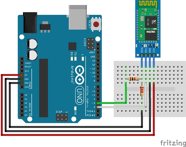
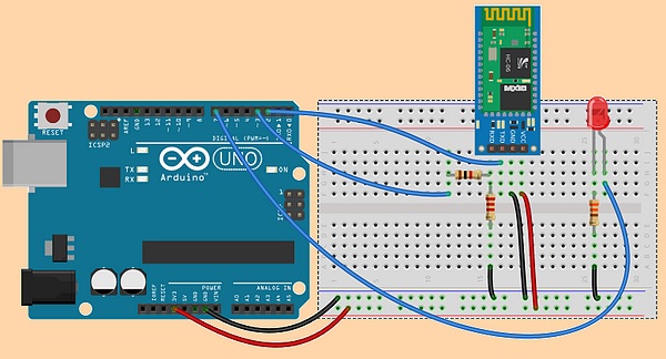
Warning: the operating voltage for HC-06 must be between 3,3V and 5 V.
But as the RX pin can only handle 3,3V, we must use a voltage divider in order to not damage the RX pin of our Bluetooth device.
This is why we need to add both 1K and 2.2k resistors to our circuit.
So this is how the final circuit looks like:
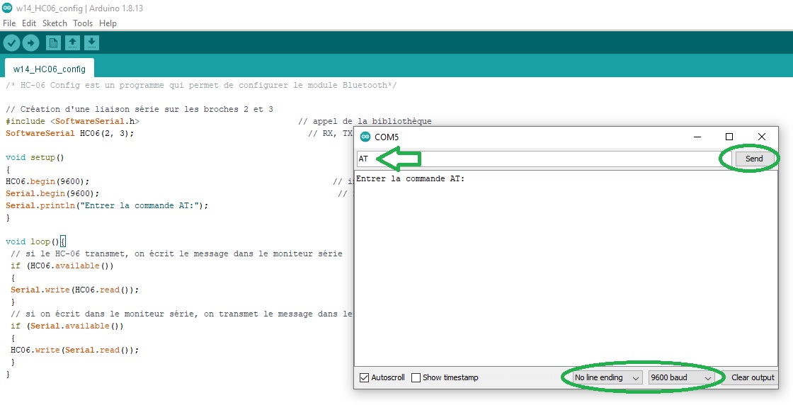
For this first test I just want to test if the wireless communication is working. Here is the code I used:
And here is the result after typing in "AT" just to test that the HC-06 Bluetooth device is responding:
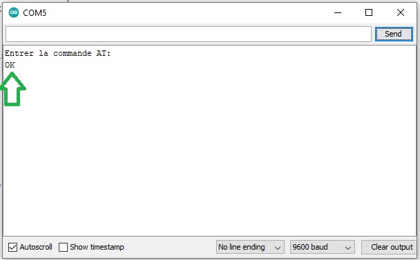
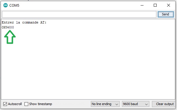
Now that I know it's working well (by receiving "OK") I also tested if I could set the baudrate with another AT command "AT+BAUD4" where 4 stand for 9600 bauds (5 stands for 19200, 6 for 38400, 7 for 57600, 8 for 115200):
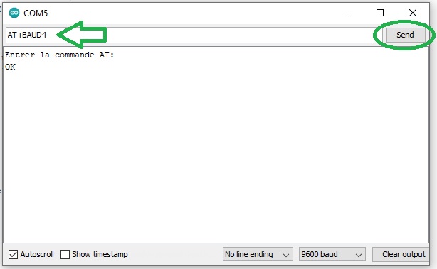
And the HC-06 device answers with "OK9600" wich shows that my Bluetooth wireless communication is working fine:
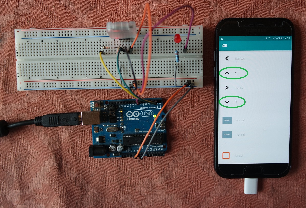
So I added a red led connected to Arduino pin 7 and a 330Ω resistor to my breadboard. The circuit is the following:
And this is the code I used:
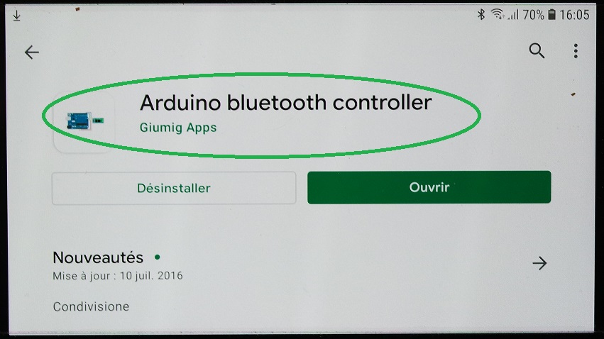
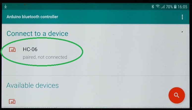
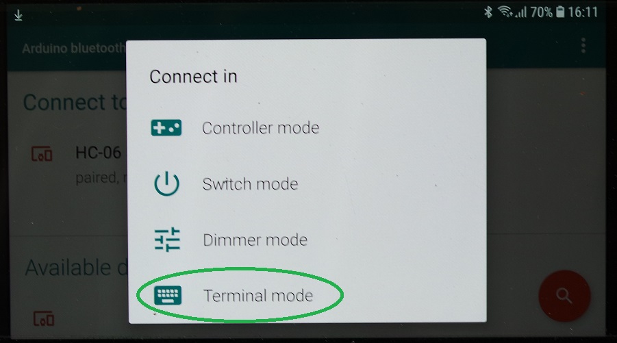
In order to be able to test I also needed to install a Bluetooth controler application on my smartphone and this is the one I used:
I then entered the "Terminal mode":
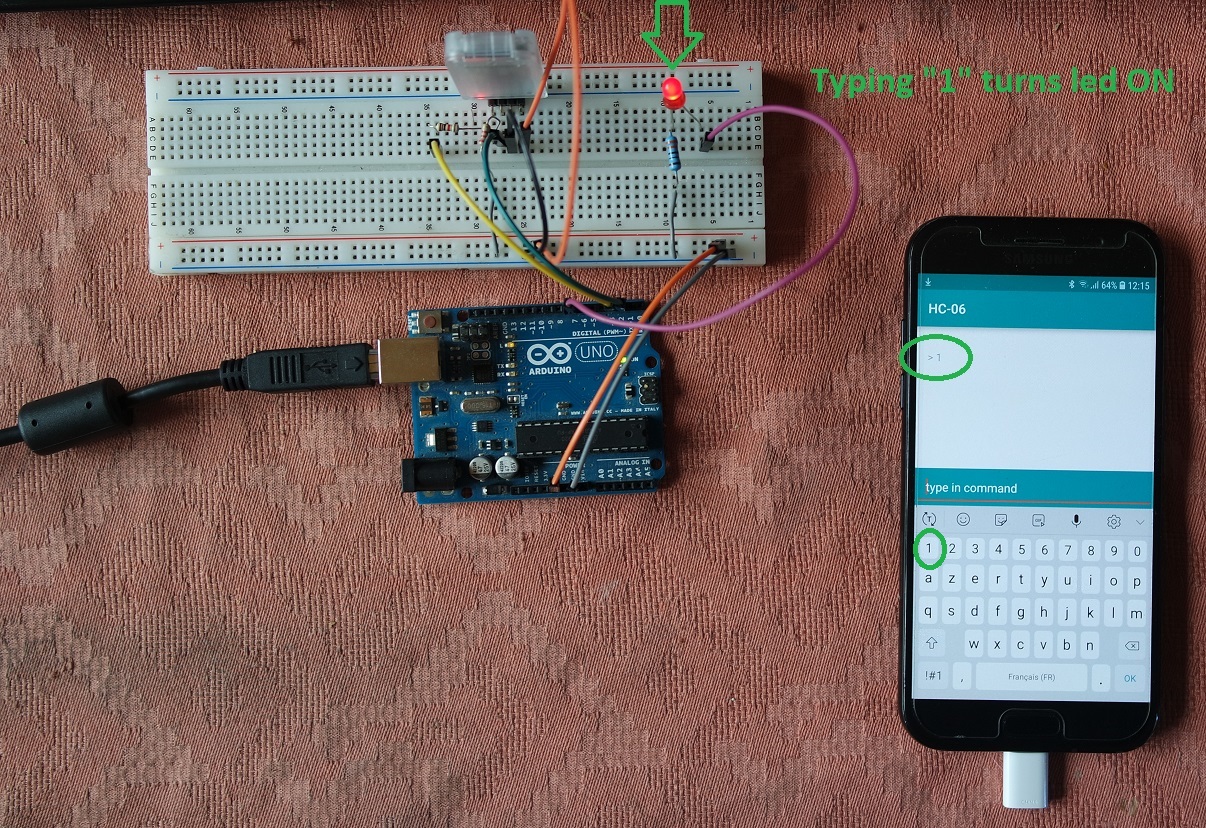
And typed "1" to turn the led ON:
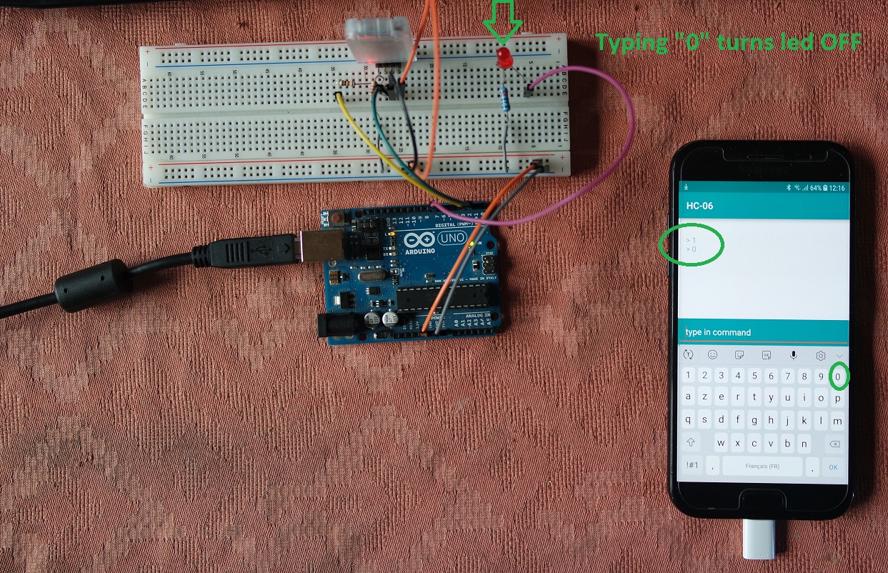
Then "0" to turn it back OFF:
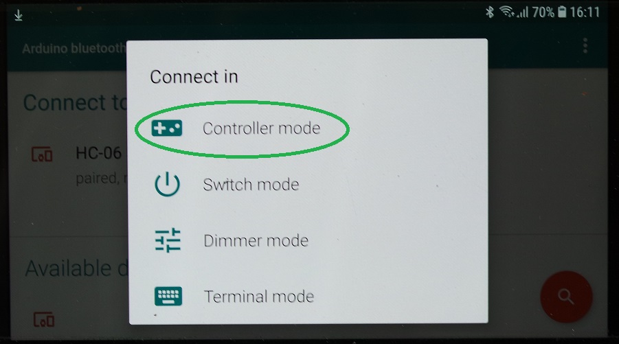
I also tried the "Controler mode" and affected "1" to the pointing up arrow and "0" to the pointing down arrow:
And here is a video showing that it's working fine:
The goal of this exercice is to display the measured distance over a small Android application on my smartphone.
The Android application is created with App Inventor 2.
I looked at some tutorials and especially this one which helped me understand how to use App Inventor 2.
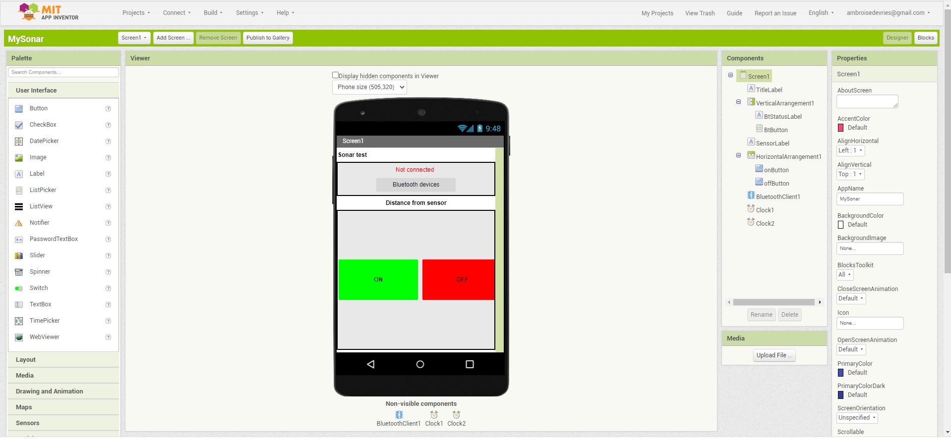
The first thing to do is to design the GUI for your Android application.
It can include labels, buttons, switches, images, etc.
This is how it looks like when I have finished my GUI design:
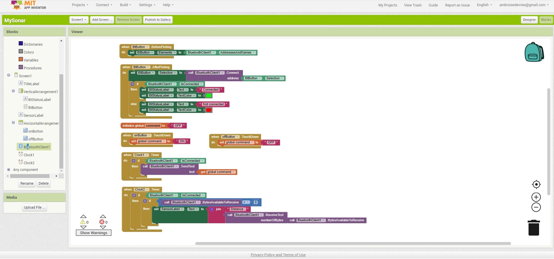
Then the second thing to do is to write the code for your Android application.
To do so in App Inventor you use blocks that will be turned into Android compatible code after compilation.
This is how my programming blocks look like when I had finished programming:
Once finished you can generate an Android compatible code by clicking on "Build/App (provide QR code for .apk)":
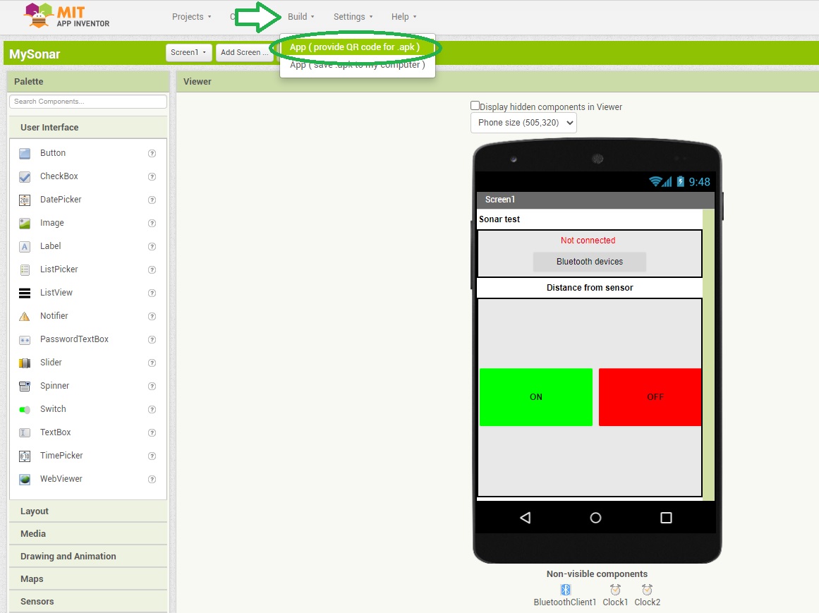
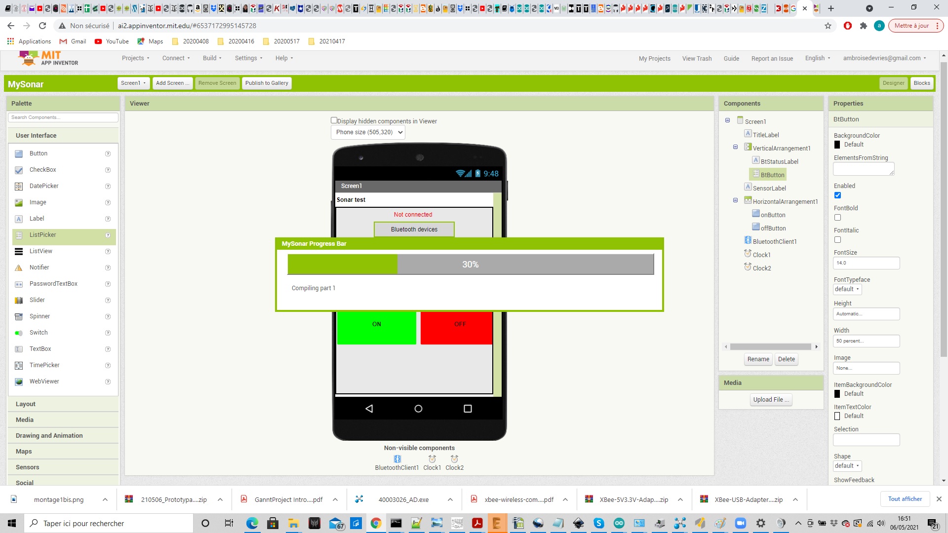
This will create the code that can then be loaded onto your Android device by flashing the provided QR code:
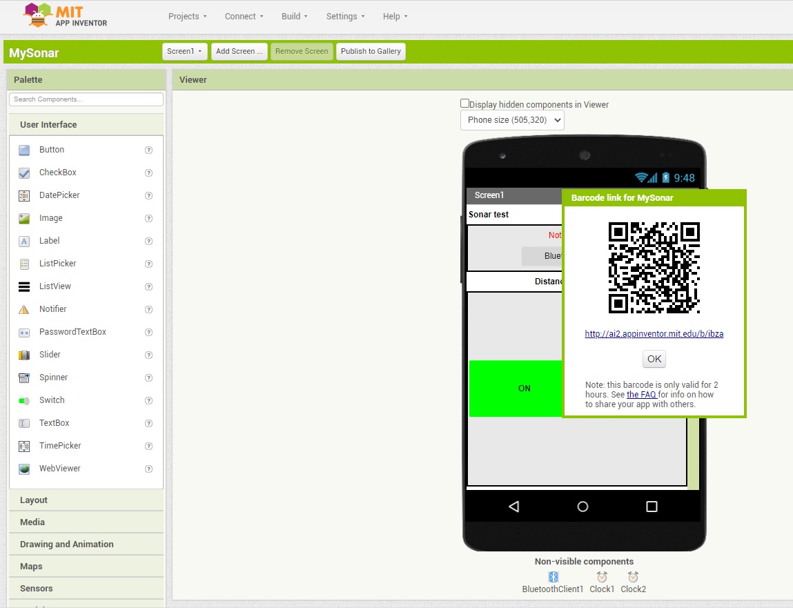
Then on you smartphone all you need is to install and use a QR code flashing app to be able to install your Android application.
Once installed you can then test it.
I started by using this sketch (that only simulate a fictive sensor value between 0 and 255) in order to test my app:
Then I reused the code I had written for my master board on week 13, and adapted it to send the distance to the smartphone instead of displaying it on a LCD display:
The values returned by the sensor are now displayed on the smartphone. And here is a video showing the result:
w14_HC06_config.ino
w14_arduino_master.ino
And the group assignment is to compare as many tool options as possible.
Group assignment
Our group assignment is documented on its own page.Individual assignment
Bluetooth communication test 1
The first thing I want to test is wireless communication between a Arduino Uno and a Bluetooth HC-06 device.I started by looking at some tutorials that could point me in the right direction, and started by following this one (in french).
For this very first test I used:
- a Arduino Uno board
- a breadboard
- a HC-06 Bluetooth device
- a 1KΩ resistor
- a 2.2 KΩ resistor
Warning: the operating voltage for HC-06 must be between 3,3V and 5 V.
But as the RX pin can only handle 3,3V, we must use a voltage divider in order to not damage the RX pin of our Bluetooth device.
This is why we need to add both 1K and 2.2k resistors to our circuit.
So this is how the final circuit looks like:
For this first test I just want to test if the wireless communication is working. Here is the code I used:
/* HC-06 Config */

// Serial communication on pins 2 and 3
#include <SoftwareSerial.h>
SoftwareSerial HC06(2, 3);           // RX, TX

void setup()
{
HC06.begin(9600);                                                 // Bluetooth serial connection initialization @ 9600 bauds
Serial.begin(9600);                                               // serial connection initialization @ 9600 bauds
Serial.println("Entrer la commande AT:");
}

void loop(){
 // if HC-06 transmit, write message
 if (HC06.available())
 {
 Serial.write(HC06.read());
 }
 // when data is written in serial monitor send it to HC-06
 if (Serial.available())
 {
 HC06.write(Serial.read());
 }
}
Once the sketch is uploaded on the Arduino Uno here are the results on my serial monitor where I'm asked to enter an AT command.And here is the result after typing in "AT" just to test that the HC-06 Bluetooth device is responding:
Now that I know it's working well (by receiving "OK") I also tested if I could set the baudrate with another AT command "AT+BAUD4" where 4 stand for 9600 bauds (5 stands for 19200, 6 for 38400, 7 for 57600, 8 for 115200):
And the HC-06 device answers with "OK9600" wich shows that my Bluetooth wireless communication is working fine:
Bluetooth communication test 2
For my second test I want to be able to control a led from an Android application on my mobile phone.So I added a red led connected to Arduino pin 7 and a 330Ω resistor to my breadboard. The circuit is the following:
And this is the code I used:
/* Bluetooth_led is to control a led from an application */

#define led 7                                    // pins affectation
#define RX 2
#define TX 3

word received_byte;                             // word that receive emitted data

// Création d'une liaison série
#include <SoftwareSerial.h>
SoftwareSerial bluetooth(RX,TX);

void setup()
{
Serial.begin(9600);                          // serial initialisation @ 9600 bauds
bluetooth.begin(9600);                       // Bluetooth serial connexion initialisation @ 9600 bauds
pinMode(led,OUTPUT) ;                        // led pin as output
}

void loop() {
ReceiveData();                                // call ReceiveData() function
if (received_byte==49)                        // if received byte is 1 (49 is ASCII code for 1)
    {
    Serial.println("Led ON");
    digitalWrite(led,HIGH);
    }
if (received_byte==48)                        // if received byte is 0 (48 is ASCII code for 0)
    {
     Serial.println("Led OFF");
     digitalWrite(led,LOW);
    }
delay(200);
    }

//function to read data from the smartphone
void ReceiveData()
{
    if (bluetooth.available())
    {
    received_byte=bluetooth.read();
    }
}
In order to be able to test I also needed to install a Bluetooth controler application on my smartphone and this is the one I used:
I then entered the "Terminal mode":
And typed "1" to turn the led ON:
Then "0" to turn it back OFF:
I also tried the "Controler mode" and affected "1" to the pointing up arrow and "0" to the pointing down arrow:
And here is a video showing that it's working fine:
Bluetooth communication test 3
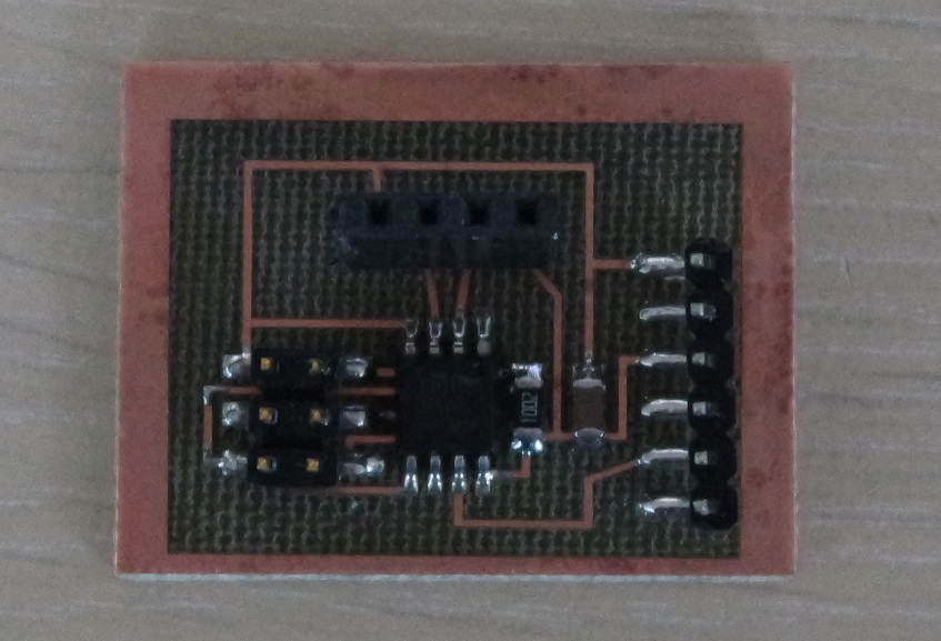
For this 3rd test I want to reuse the board I designed on week 10 and that drives a HC-SR04 sonar device.The goal of this exercice is to display the measured distance over a small Android application on my smartphone.
The Android application is created with App Inventor 2.
I looked at some tutorials and especially this one which helped me understand how to use App Inventor 2.
MIT App Inventor
App Inventor let you easily create Android applications that can be used on a Smartphone.The first thing to do is to design the GUI for your Android application.
It can include labels, buttons, switches, images, etc.
This is how it looks like when I have finished my GUI design:
Then the second thing to do is to write the code for your Android application.
To do so in App Inventor you use blocks that will be turned into Android compatible code after compilation.
This is how my programming blocks look like when I had finished programming:
Once finished you can generate an Android compatible code by clicking on "Build/App (provide QR code for .apk)":
This will create the code that can then be loaded onto your Android device by flashing the provided QR code:
Then on you smartphone all you need is to install and use a QR code flashing app to be able to install your Android application.
Once installed you can then test it.
I started by using this sketch (that only simulate a fictive sensor value between 0 and 255) in order to test my app:
#define RX 2
#define TX 3

#include <SoftwareSerial.h>

SoftwareSerial bluetooth(RX,TX);

String cmd="";
float sensor_val=0;

void setup(){
  //Initialize Serial Monitor
  Serial.begin(9600);
  //Initialize Bluetooth Serial Port
  bluetooth.begin(9600);
}

void loop(){
  //Read data from HC06
  while(bluetooth.available()>0){
    cmd+=(char)bluetooth.read();
  }

  //Select function with cmd
  if(cmd!=""){
    Serial.print("Command recieved : ");
    Serial.println(cmd);
    // We expect ON or OFF from bluetooth
    if(cmd=="ON"){
        Serial.println("Function is on");
    }else if(cmd=="OFF"){
        Serial.println("Function is off");
    }else{
        Serial.println("Function is off by default");
    }
    cmd=""; //reset cmd
  }
  // Simulate sensor measurement
  sensor_val=(float)random(256); // random number between 0 and 255

  //Write sensor data to HC06
  bluetooth.print(sensor_val);
  delay(100);
}
And here is a video showing that it works fine:Then I reused the code I had written for my master board on week 13, and adapted it to send the distance to the smartphone instead of displaying it on a LCD display:
/*
This sketch runs on an Arduino connected to an ATtiny85 running w13_ATtiny85_slave.ino
The data received is from a HC-SR04 sensor
 */

#include <Wire.h>

String cmd="";
byte distance;                              // Where the Distance is stored (8 bit unsigned)

#define RX 2
#define TX 3

#include <SoftwareSerial.h>
SoftwareSerial bluetooth(RX,TX);

void setup()
{
  Wire.begin();
  Serial.begin(9600);

  //Initialize Bluetooth Serial Port
  bluetooth.begin(9600);
}

void loop(){
  //Read data from HC06
  while(bluetooth.available()>0){
    cmd+=(char)bluetooth.read();
  }

    //Select function with cmd
  if(cmd!=""){
    Serial.print("Command recieved : ");
    Serial.println(cmd);
    // We expect ON or OFF from bluetooth
    if(cmd=="ON"){
        Serial.println("Function is on");
    }else if(cmd=="OFF"){
        Serial.println("Function is off");
    }else{
        Serial.println("Function is off by default");
    }
    cmd=""; //reset cmd
  }

  Wire.requestFrom(7, 1);                  // The TinyWire library only allows for one byte to be requested at a time
  while (Wire.available() == 0)  ;         // Wait until there is data in the I2C buffer

  distance = Wire.read();                  // Read the first (and hopefully only) byte in the I2C buffer

  //Write sensor data to HC06
  bluetooth.print(distance);
  delay(1000);
}
The values returned by the sensor are now displayed on the smartphone. And here is a video showing the result:
Files for this week
w14_HC06_led.inow14_HC06_config.ino
w14_arduino_master.ino