Electronics Production
This week I worked on etching PCB with the fiber laser cutter of the Fablab and learn how to solder properly. We also worked all together to characterize the design rules for PCB production process.
And I also made a FABTinyISP.
Then I tried to reproduce it on the laser cutter we have in our school (a Trotec 100 Flexx).
Many settings were tried until good results where obtained with
It needs to be fine tuned by hand while engraving some test picture until a bright green light color appears. The machine is then put in "error mode" by slightly opening the door.
By doing so, the last focus is kept and can then be used to engrave the PCB.
I also added a Z offset at the beginning of the process to avoid the manual fine-tuning step. After trials, a 1mm Z offset (focus shorten by 1mm) gave a good focus point (bright green light)
The process is now simplified (no more fine tuning step) and the result of crossing the engraving direction for each pass improved the result.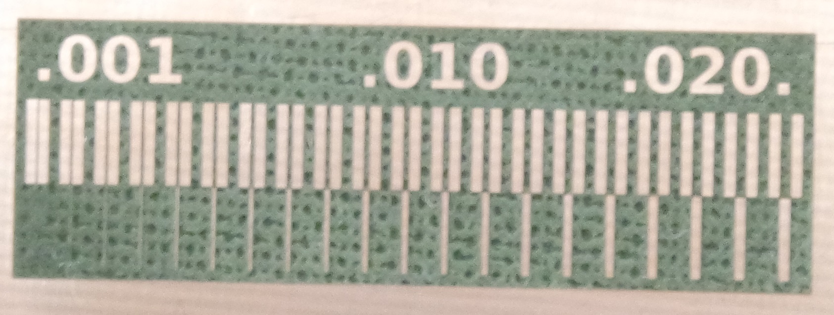
It's showing that a 0.002mm clearance between traces can be achieved. But in practice, and to make sure, a clearance of 0.004mm seems better.
A trace of 0.003mm thickness can also be achieved but for better result it should also be at least 0.004mm.
These results were achieved on a Trotec Speedy 100 Flexx.
And this year as a group assignment (I'm a continuing student from 2020), we added text at different size (from 2mm to 0.75mm high) and engraved it again on a Epilog GS24.
We can see that the smallest trace size we can use is 0.4mm wide on the Epilog.
The FABtinyISP is a USB AVR programmer and SPI interface.

The engraving image can be used as is for engraving the PCB in raster mode. But the cutting one must be converted into vectors. The vectorization process was done in Coreldraw which is also the software we use to send the print job to the laser cutter.
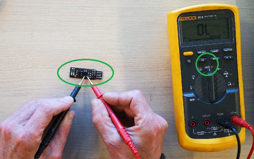
After the engraving and cutting is done, the PCB is checked for any errors due to fine copper hair that might do a short. To do so we use a multimeter to check that everything that should be connected is OK and that things that shouldn't connect don't.
And if everything is fine the soldering step can take place.
List of needed components:
Now the soldering step can start following this schematic and board images:
Soldering is completely new for me so I started to look at some tutorials and at first I found it difficult to get nice and shiny soldering. But fortunately Jonah (our instructor) showed me how to achieve better solderings and after some trials they started to look better.
After each component is added the PCB is tested again to make sure it's been soldered properly and to avoid discovering a potential failure in the end.
This is a photo of my finished ugly board: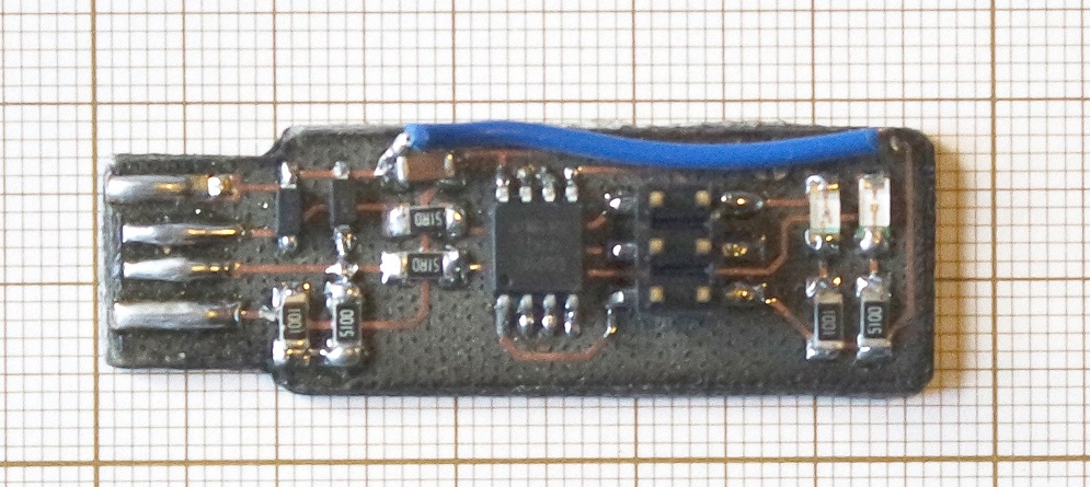
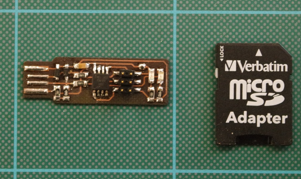
And this is the one I've been redoing this year. I'm in progress:
I started by installing the Atmel GNU toolchain thru installing Atmel Studio.
I also installed GNU Make and avrdude as per the tutorial.
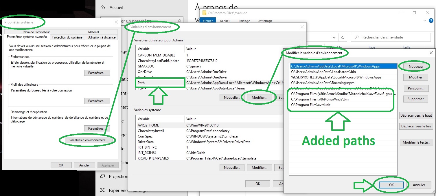
I then followed the procedure to update Windows path environment variable:
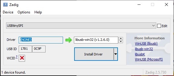
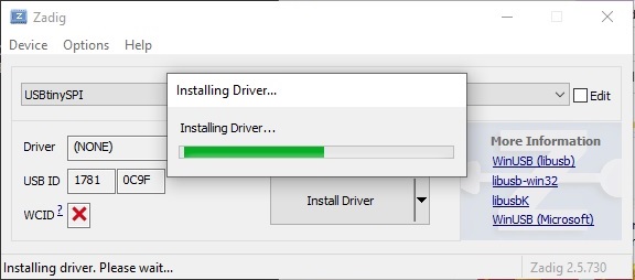
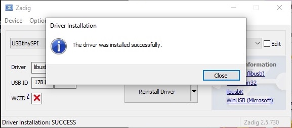
And also installed drivers for the USBtiny by using the recommended Zadig tool:
The final sanity check shows that everything is working as expected:
I also tried another route: under Windows 10 there is a feature I had unnoticed : we can now install a native Linux terminal.
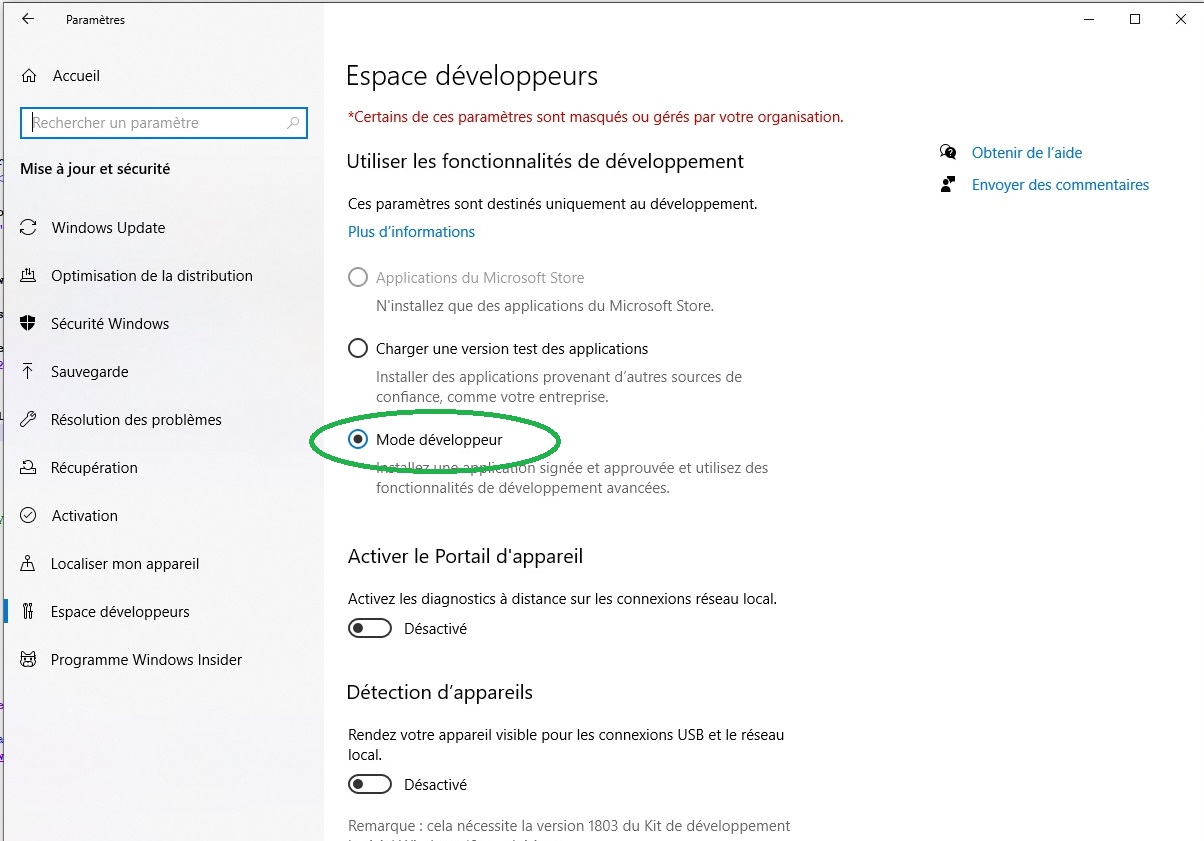
Step 1 : Enable developer mode
Go to Settings => Update and security => For developers and activate Developer mode:
Step 2 : Linux subsystem installation
On your Control panel go to Programs => Turn Windows feature on or off: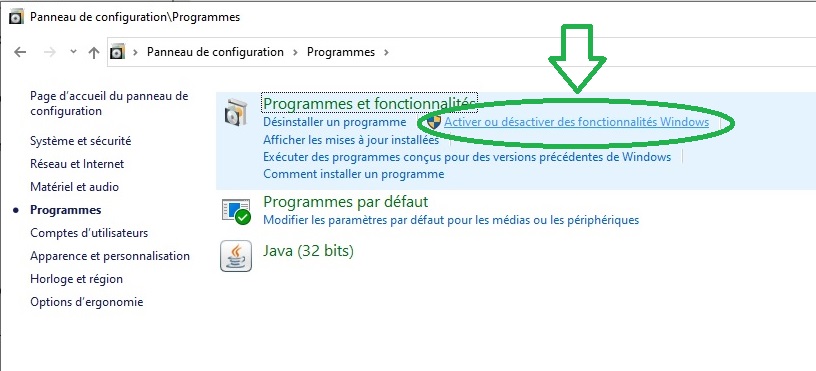
In the window that shows, activate Windows Subsystem for Linux: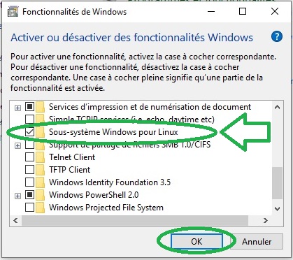
It's then adviced to restart your computer.
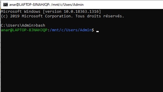
When done you now have access to a functionning native linux terminal by simply typing bash in your Windows terminal:
From there we can now follow the software installation procedure for Linux.
Depending on the one we have, in my case an Atmel-ICE, we need to update the file named Makefile and modify the following lines like this :
We can now plug our board in a USB 2.0 port.
At this stage the red led on my board turns on which is a good point according to the tutorial.
The Atmel-ICE is then connected to the ISP headers of the board by making sure to plug pin 1 in the correct place. It's the one marked by a yellow dot in the schematic with MISO signal connection (see the shematic image above).
We will then erase the chip and program its flash memory with the .hex file we generated earlier by typing
We then need to set the fuses which will allow to check if the board is recognized as a regular USB device. We do that by running a
And to check that the board works well and is recognized as a USB device we enter a
We have to note the USB and Device numbers that we will need to know in a further step later. Here in my case 002 and 025 respectively.
Next we have to blow the reset fuse. We first connect the Atmel-ICE back on the board and run a
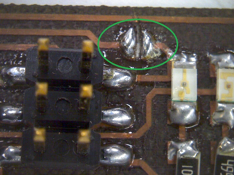
It's now time to break the connection on the solder jumper of our board by removing solder and thus braking the trace.
Our board has now become a ISP programmer but we need to make sure it actualy works as intended.
For that we can simply try to program an Arduino board with it.
Our instructor and colleague Jonah has written a small C++ program that blinks the led at a certain speed and I used it to program a Arduino Mega board with the kind help of Quentin (another student/colleague. Thanks man!).
The command to flash the Arduino is
where
PCB etching
As a group we worked on how to engrave the copper layer of a piece of FR4 with the laser cutter (Epilog).Then I tried to reproduce it on the laser cutter we have in our school (a Trotec 100 Flexx).
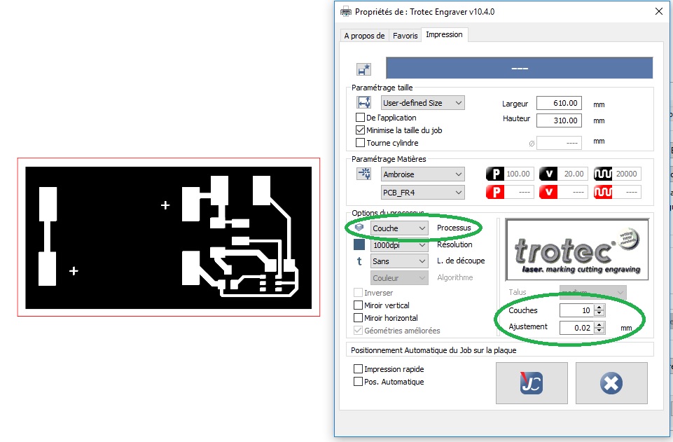
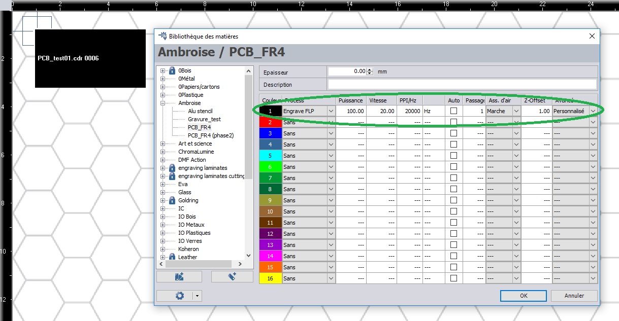
Many settings were tried until good results where obtained with
- Power 100 (%)
- Speed 40 (%)
- Frequency 20000
- Air assist ON
- Number of passes 7
It needs to be fine tuned by hand while engraving some test picture until a bright green light color appears. The machine is then put in "error mode" by slightly opening the door.
By doing so, the last focus is kept and can then be used to engrave the PCB.
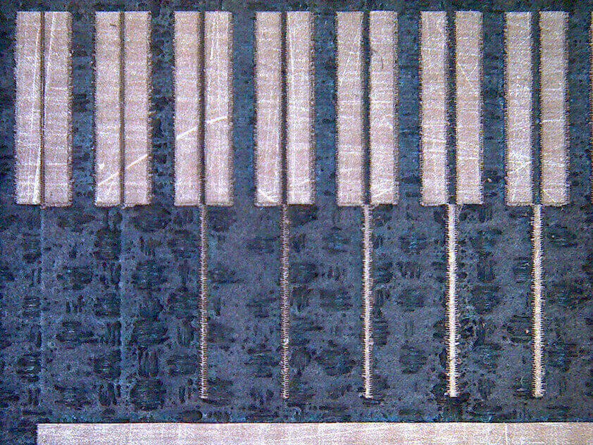
Improving the settings
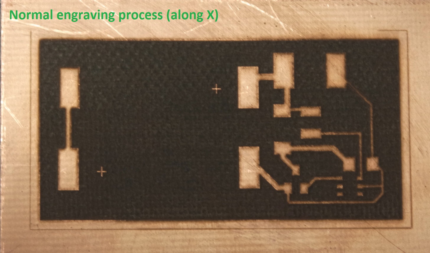
While the previous process works fine, it needs manual adjustment (fine tuning the focus) and the result shows parallel lines under microscope due to the engraving process occuring along the X axis.Cross etching
I wondered if the laser machine could also engrave along the Y axis and after reading the Trotec documentation I found an engraving mode which seemed worth a try. It's called "Layers".In this special engraving mode you can
- set a number of passes (layers - between 2 and 255)
- define a Z adjustment at each layer change (re-focus)
- alternate the engraving direction in between passes (X / Y axis)
I also added a Z offset at the beginning of the process to avoid the manual fine-tuning step. After trials, a 1mm Z offset (focus shorten by 1mm) gave a good focus point (bright green light)
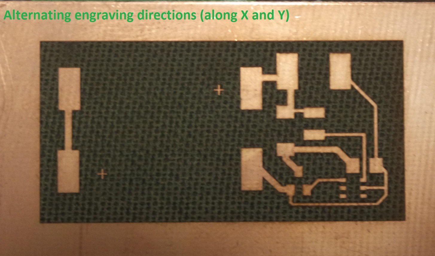
The process is now simplified (no more fine tuning step) and the result of crossing the engraving direction for each pass improved the result.
Here are the screenshots for this setting:
Here is a video showing the alternated engraving directions:
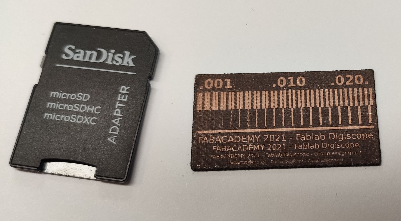
And here are the results:
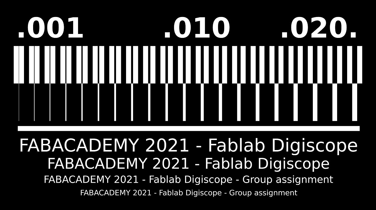
Testing the limits
This benchmark image was engraved to test the limits of this method and here are the results:It's showing that a 0.002mm clearance between traces can be achieved. But in practice, and to make sure, a clearance of 0.004mm seems better.
A trace of 0.003mm thickness can also be achieved but for better result it should also be at least 0.004mm.
These results were achieved on a Trotec Speedy 100 Flexx.
And this year as a group assignment (I'm a continuing student from 2020), we added text at different size (from 2mm to 0.75mm high) and engraved it again on a Epilog GS24.
We can see that the smallest trace size we can use is 0.4mm wide on the Epilog.
Making a FABTinyISP programmer
Following the very detailed instructions provided I started the FABTinyISP programmer.The FABtinyISP is a USB AVR programmer and SPI interface.
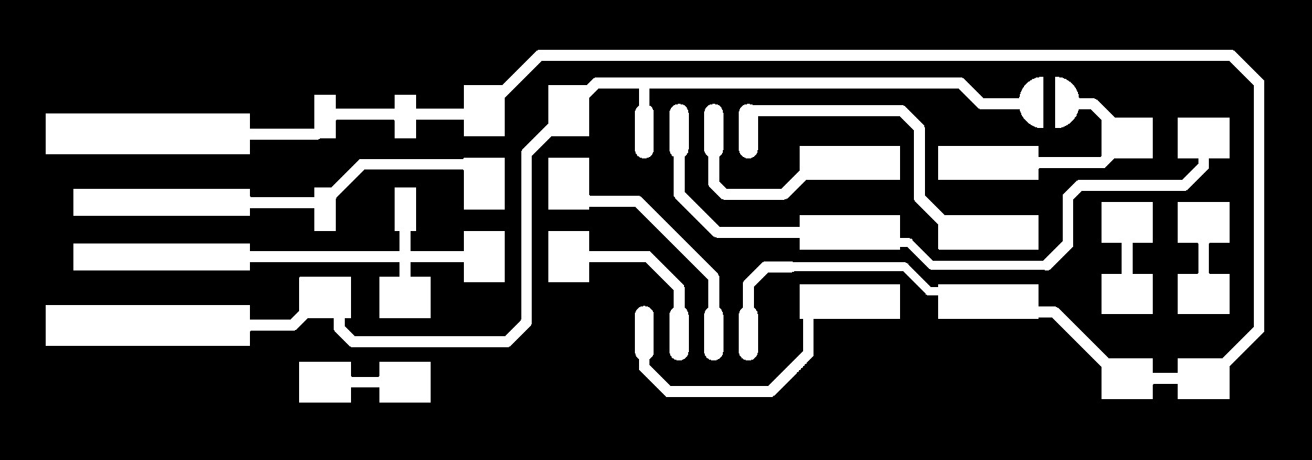
Engraving and cutting steps
The engraving and cutting images are provided:The engraving image can be used as is for engraving the PCB in raster mode. But the cutting one must be converted into vectors. The vectorization process was done in Coreldraw which is also the software we use to send the print job to the laser cutter.
After the engraving and cutting is done, the PCB is checked for any errors due to fine copper hair that might do a short. To do so we use a multimeter to check that everything that should be connected is OK and that things that shouldn't connect don't.
And if everything is fine the soldering step can take place.
Soldering step
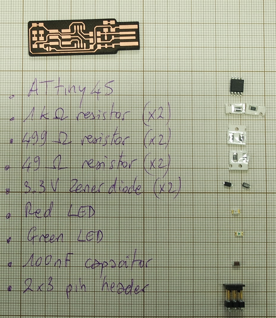
The first thing to do before starting to solder is to make a list of all the components needed and to get organized.List of needed components:
- 1x ATtiny45 or ATtiny85
- 2x 1kΩ resistors
- 2x 499Ω resistors
- 2x 49Ω resistors
- 2x 3.3v zener diodes
- 1x red LED
- 1x green LED
- 1x 100nF capacitor
- 1x 2x3 pin header
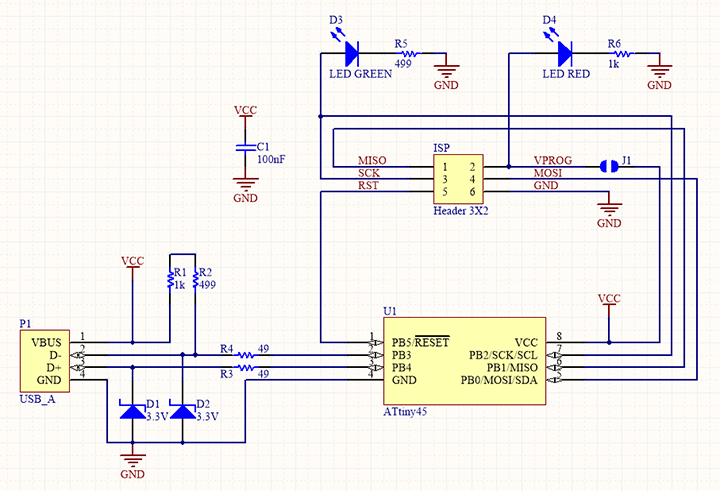
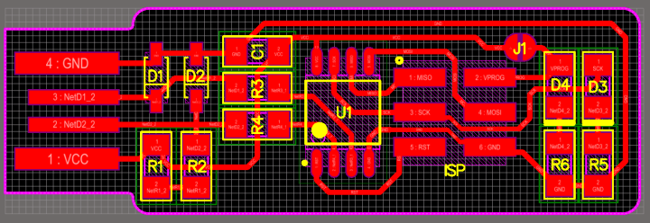
Now the soldering step can start following this schematic and board images:
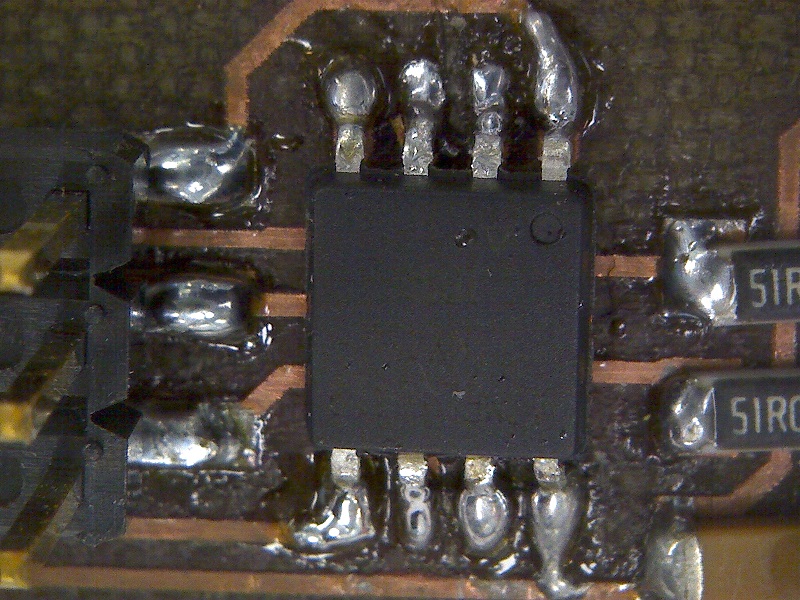
Soldering is completely new for me so I started to look at some tutorials and at first I found it difficult to get nice and shiny soldering. But fortunately Jonah (our instructor) showed me how to achieve better solderings and after some trials they started to look better.
After each component is added the PCB is tested again to make sure it's been soldered properly and to avoid discovering a potential failure in the end.
This is a photo of my finished ugly board:
And this is the one I've been redoing this year. I'm in progress:
Programming step
Bash install on Windows 10
I followed this tutorial which explains that installing all the packages needed under Windows is much harder than doing it under Linux.I started by installing the Atmel GNU toolchain thru installing Atmel Studio.
I also installed GNU Make and avrdude as per the tutorial.
I then followed the procedure to update Windows path environment variable:
And also installed drivers for the USBtiny by using the recommended Zadig tool:
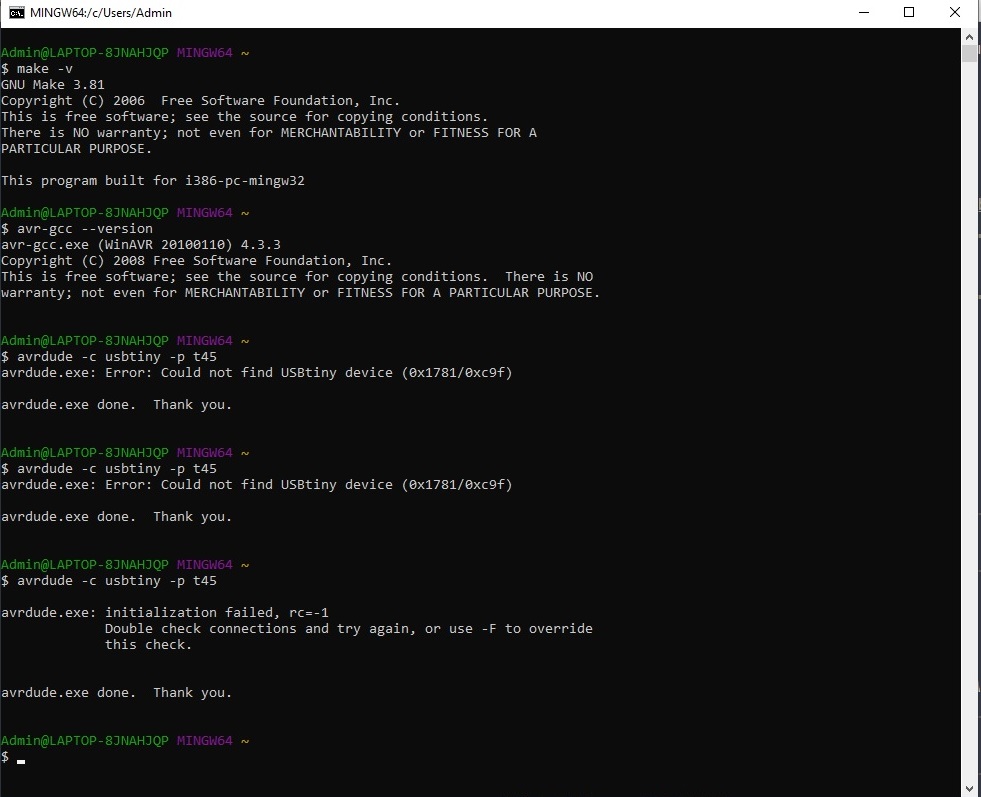
The final sanity check shows that everything is working as expected:
I also tried another route: under Windows 10 there is a feature I had unnoticed : we can now install a native Linux terminal.
Step 1 : Enable developer mode
Go to Settings => Update and security => For developers and activate Developer mode:
Step 2 : Linux subsystem installation
On your Control panel go to Programs => Turn Windows feature on or off:
In the window that shows, activate Windows Subsystem for Linux:
It's then adviced to restart your computer.
When done you now have access to a functionning native linux terminal by simply typing bash in your Windows terminal:
From there we can now follow the software installation procedure for Linux.
Software install under Linux
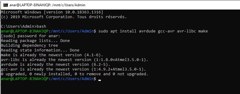
Under Linux you can simply typesudo apt install avrdude gcc-avr avr-libc make to install avrdude wich allows to communicate with a AVR microchip:Building the firmware
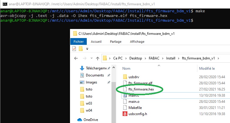
The firmware source code can be downloaded here as a zip archive which then needs to be unzipped. Then change to the directory where you unzipped it and runmake. This will build a .hex file:
Programming the microchip
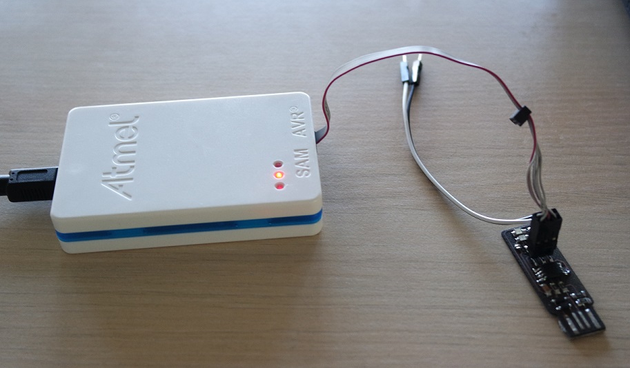
Before to become a programmer itself, the ATtiny45 needs to be programmed with the help of... another programmer.Depending on the one we have, in my case an Atmel-ICE, we need to update the file named Makefile and modify the following lines like this :
MCU = attiny45
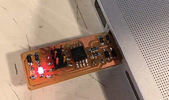
PROGRAMMER ?= atmelice_ispWe can now plug our board in a USB 2.0 port.
At this stage the red led on my board turns on which is a good point according to the tutorial.
The Atmel-ICE is then connected to the ISP headers of the board by making sure to plug pin 1 in the correct place. It's the one marked by a yellow dot in the schematic with MISO signal connection (see the shematic image above).
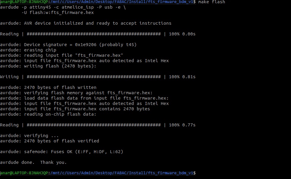
We will then erase the chip and program its flash memory with the .hex file we generated earlier by typing
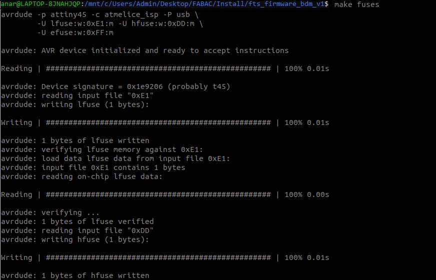
make flash:We then need to set the fuses which will allow to check if the board is recognized as a regular USB device. We do that by running a
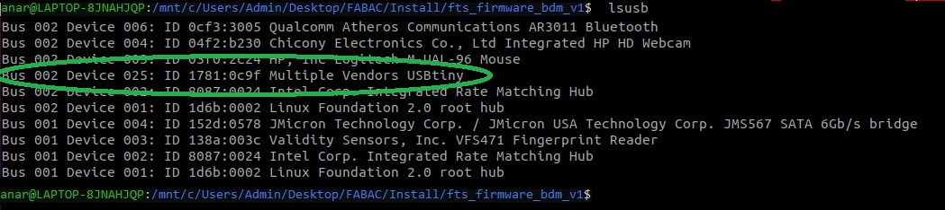
make fuses command:And to check that the board works well and is recognized as a USB device we enter a
lsusb command wich will list our USB devices:We have to note the USB and Device numbers that we will need to know in a further step later. Here in my case 002 and 025 respectively.
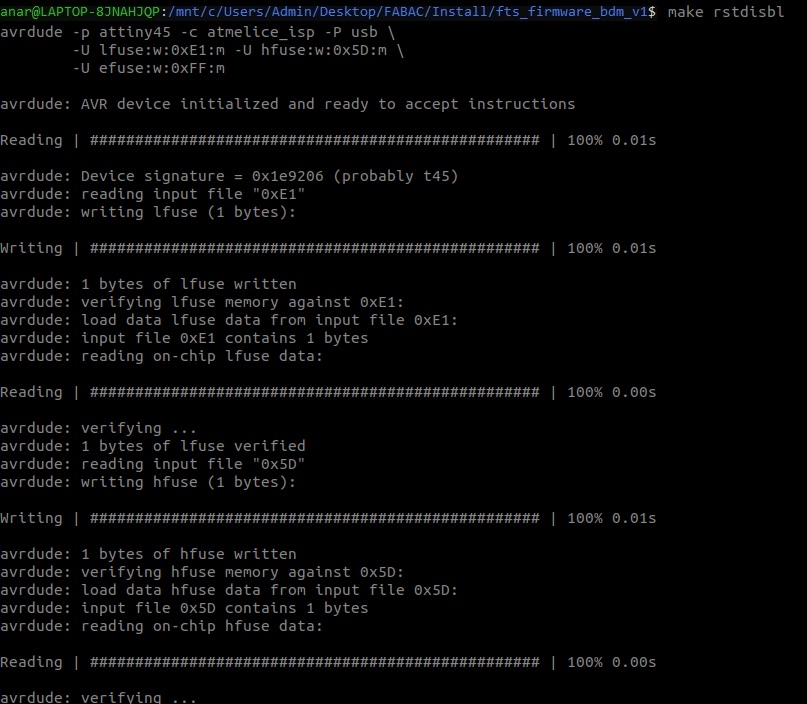
Next we have to blow the reset fuse. We first connect the Atmel-ICE back on the board and run a
make rstdisbl command:It's now time to break the connection on the solder jumper of our board by removing solder and thus braking the trace.
Our board has now become a ISP programmer but we need to make sure it actualy works as intended.
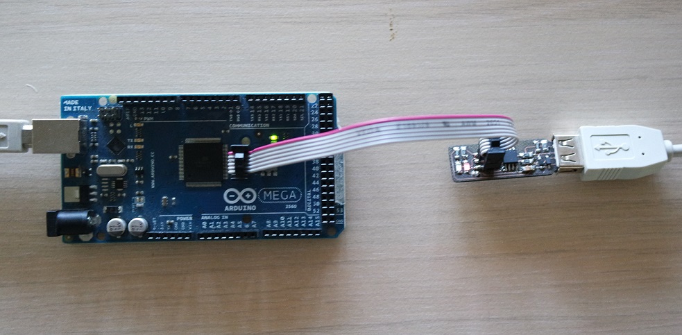
For that we can simply try to program an Arduino board with it.
Our instructor and colleague Jonah has written a small C++ program that blinks the led at a certain speed and I used it to program a Arduino Mega board with the kind help of Quentin (another student/colleague. Thanks man!).
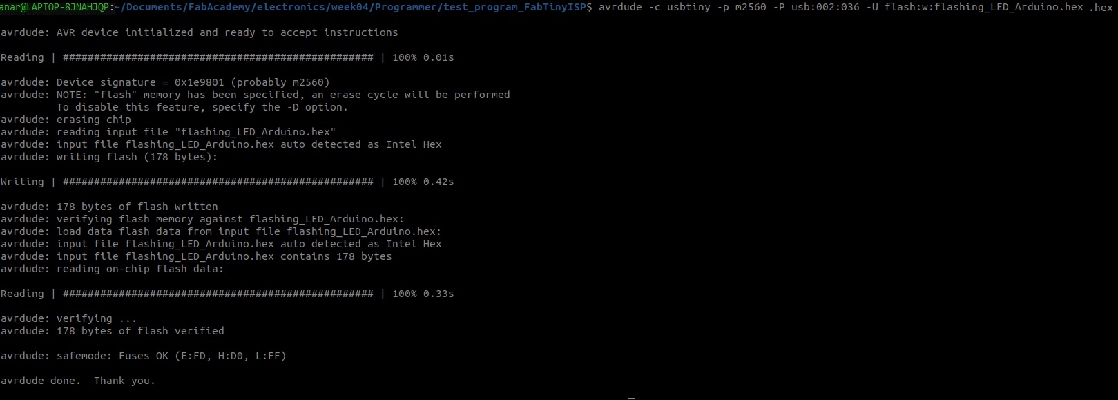
The command to flash the Arduino is
avrdude -c usbtiny -p m2560 -P usb:002:036 -U flash:w:flashing_LED_Arduino.hexwhere
- -c usbtiny tells which programmer is used (my board)
- -p m2560 tells which microchip we're programming and m2560 is for the ATmega2560
- -P usb:002:025 is the USB port to which our board is connected (we noted these numbers earlier)
- -U flash:w:flashing_LED_Arduino.hex indicates which program we want to flash