Embedded programming
The group assignement for this week is to compare the performance and development workflows for other architectures. But we were unable to do it because our Fablab is closed (COVID-19).
The individual assignment is to read a microcontroller data sheet, program our board to do something and use as many programming languages and environments as possible.
I followed both this tutorial and this other one to help me in the process.
An ISP allows AVR microcontrollers to be programmed without having to remove them from the board.
Six wires are needed to program an AVR microcontroller.
Three of these wires are for Serial Peripheral Interface (SPI) and are:
The "Slave" is the AVR chip you want to program.
The other three wires are:
It's needed in the process and can be downloaded here.
Once installed we first need to add support for the ATtiny in the Arduino IDE.
In
Then if we go to
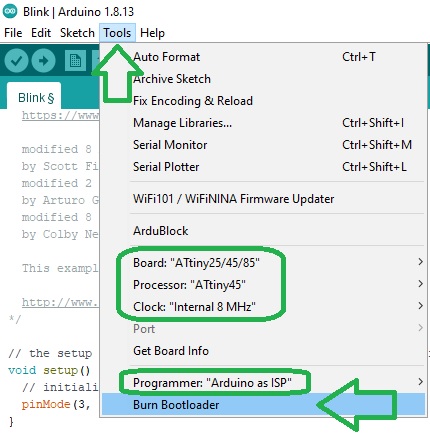
The ATtiny45 runs at 1MHz by default and if we want to make it run at 8MHz we need to burn the bootloader first by clicking on
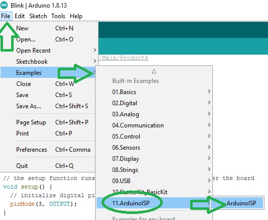
Now we can turn the Arduino into an ISP by loading
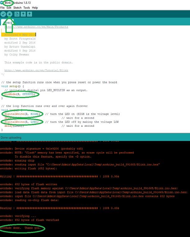
Our Arduino Uno is now configured as an ISP programmer and we can use it to send code to the target AVR of our board:
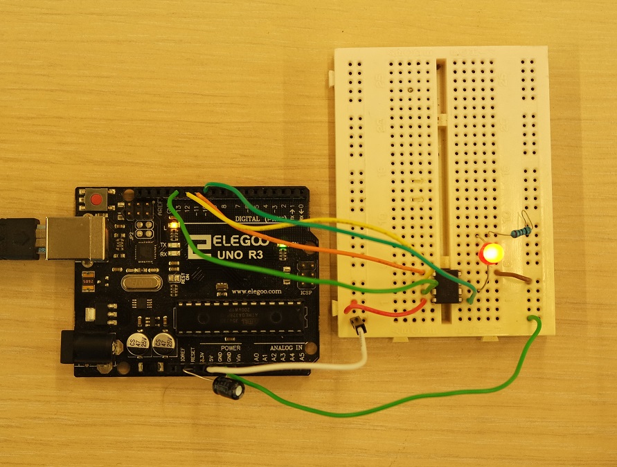
Now we need to connect our board to the Arduino and here is how everything is connected:
Once everything is connected we can use the Arduino IDE to write code and load it into our AVR. First tested on an ATtiny45 fixed to a breadboard:
And then on my board:
This first line of code creates an integer variable to store the current state of the button.
It's inserted before the setup function:
Pins are configured inside the setup function with pinMode().
Pin 4 (the pushbutton) is set as an input and pin 3 (the LED) is set as an output:
In the main loop the digitalRead() function is used to read the state of pin 4 which can be either HIGH (5V) or LOW (ground), and stores it in the buttonState variable:
Then there is an if statement to check if buttonState is HIGH.
If the condition is true, pin 3 (the LED) is set to HIGH (turned on) with digitalWrite().
Otherwise the code inside the else statement is executed and pin 3 (the LED) is set to LOW (turned off):
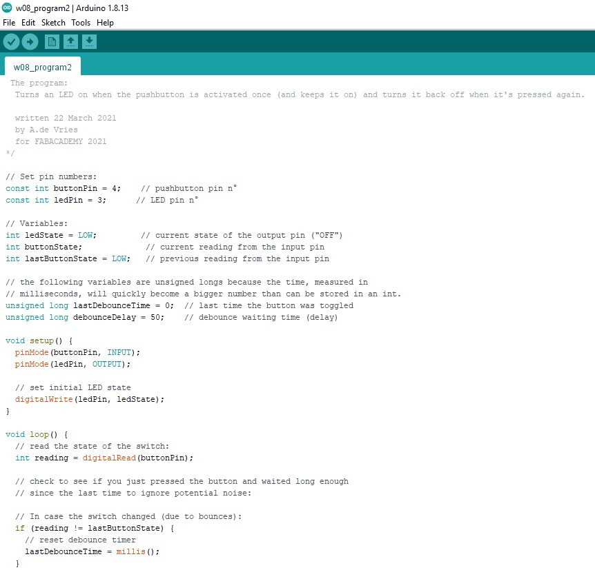
Next I tested another one that turns on the led when the button is pushed once (and keeps it on), and turns it off when the button is pressed once again:
It's very well explained and helped me a lot in understanding what was all this week about (and the next ones).
I hardly recommend it!
Here are the 2 first chapters that already teached me a lot!
While reading it, I started to think of another method using "regular" C programming and compiler. Unfortunately I wasn't able to finish testing that route because I've been missing time.
But following are the things that I started to do and to note down.
That means we must somehow send some code we have written from our computer to the microcontroler on our board.
And this requires several tools:
The compiler we've been using so far in the previous electronic weeks is
A flash programmer needs to be connected between the source computer and the target AVR microcontroller.
It could be either the ATMELice we have at our lab, the FABtinyISP we made on week 4, or an Arduino board.
Under Windows OS the toolchain can be installed by installing WinAVR.

Planning ahead is the very 1st step before getting into writing source code.
The board we made on week 6 has a push button and a led that could be used has an input and output to light lhe led when the button is pushed down for example.
This is the structure of a typical AVR C code:
In the preamble section you can include pieces of code from other source files, define variables and functions.
Then comes the
It's inside that loop that we must put our instructions and tell the AVR what to do (like blinking a led for example).
Blinking LED program example:
I want the LED on my board to only light up when the button will be pushed down.
The led on my board is connected to PB3 and the push button to PB4.
By default DDRB (Data Direction Register B) pins are all set to zero which means they are configured as inputs.
I want to configure them all as outputs except for my button that's connected to PB4:
My LED being on PB3, in the main loop the code that will turn it on or off now becomes:
I need to turn the led on only when the push button is pressed down so I need to read its state.
My push button being connected to PB4, I need to know if the value of the fourth pin of the PINB register has changed (PB4).
Testing a bit state can be done with a AND logical operator and a bitmask because an AND operator will only return 1 if both bits are 1.
So by using a bitmask (with a 1 in bit four) and a AND logical boolean, I can test if it returns zero (false) or anything else (true).
This is how to set a bitmask with a 1 in bit four:
A AND logical boolean between our bitmask byte and the input register PINB will return something else than zero (true) if the pin 4 of our input register has been set. Therefore we can simply test:
Like I said above, I've been missing time to explore that route better...
TEXT FROM 2020 COVID LOCKDOWN
Unfortunately the board I had planned isn't finished and as I can't go back to our Fablab, I used an Arduino board instead for getting used to write some code. The board is a Mega 2560.
But before to start coding, we must first connect everything to the Arduino.
The initial board needed to have a push button and a LED. So I will need these to also be connected on the Arduino.
Before to physically connect my components to the Arduino, I planned everything on Tinkercad just to make sure and not taking the risk to fry anything.
I started by adding an Arduino Uno board and a small breadboard by dragging them from the components panel (on the right) to the workplane.
Then I connected the Arduino 5V to the breadboard power (+) and the Arduino ground (GND) to the ground rail (-) by creating colored wires.
In the same way I connected the power and ground rails to their respective buses on the opposite side of the breadboard with a red wire (power) and a black wire (ground).
A LED and a 1K Ohms resistor are also added. The LED is plugged into two different rows with the cathode (negative, short leg) connected to one leg of the resistor.
The orientation of the resistor isn't important because resistors are not polarized but it's not the case for the LED.
The other leg of the resistor is connected to ground, and the LED anode (positive, long leg) is connected to the Arduino pin 13.
A pushbutton is needed to trigger the LED so I added one in the center of the breadboard (column break) and connected one button leg to power, and the diagonally opposite leg to pin 2.
I also added a high value resistor (10K Ohms) between that same button leg and the ground to act as a "pull-down" and a multimeter between Arduino pin 2 and ground.
This is my final circuit:
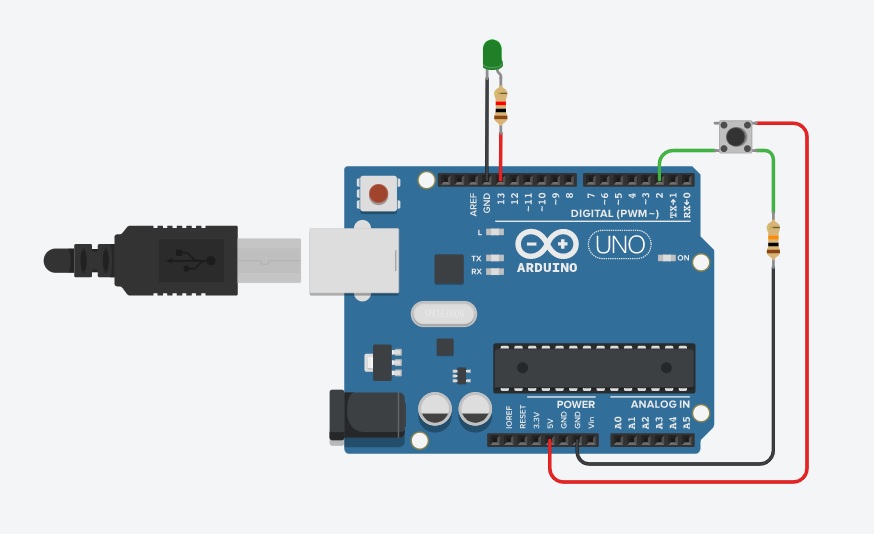
And here is another version without a breadboard that is easier to understand:
This code is copy/pasted in TinkerCAD's place for "Code" and a simulation is launched ("Start simulation"). The signal being seen by pin 2 is displayed on the multimeter:
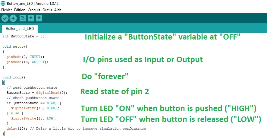
This first line of code creates an integer variable to store the current state of the button.
It's inserted before the setup function:
Pins are configured inside the setup function with pinMode().
Pin 2 (the pushbutton) is set as an input and pin 13 (the LED) is set as an output:
In the main loop the digitalRead() function is used to read the state of pin 2 which can be either HIGH (5V) or LOW (ground), and stores it in the buttonState variable:
Then there is an if statement to check if buttonState is HIGH.
If the condition is true, pin 13 (the LED) is set to HIGH (turned on) with digitalWrite().
Otherwise the code inside the else statement is executed and pin 13 (the LED) is set to LOW (turned off):
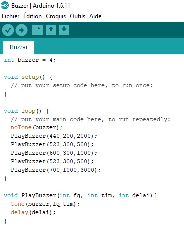
I also wrote another small program to play sounds on a buzzer but this time I used a Arduino Uno:
It makes programming more intuitive without the annoyance of syntax error and lets you better focus on the program's tasks.
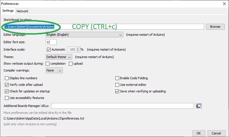
An easy way to locate it on your computer is to launch the Arduino IDE, go into the "Preferences" menu and copy the Sketchbook location:
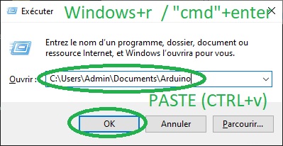
Then launch an "Execute" command by pressing "Windows + r" / "cmd" + Enter and paste the previously copied path here then press "Enter":
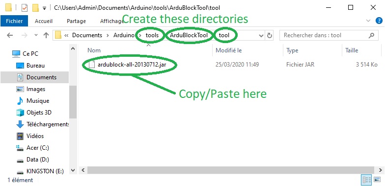
Once at the correct location, you have to create a "tools" directory, another "ArduBlockTool" directory within it, and finally another "tool" directory within the previous one and paste the previously downloaded .jar file here:
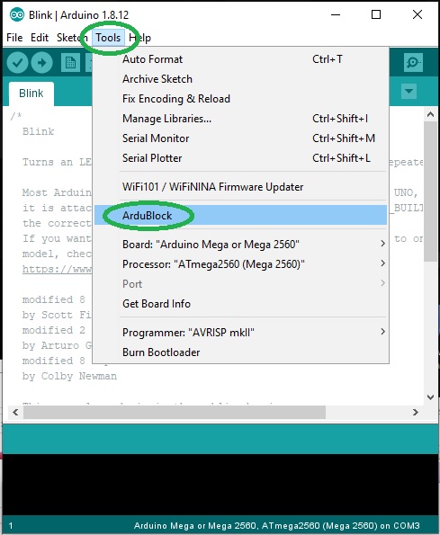
You can then relaunch Arduino IDE and check that Ardublock now appears under the "Tool" menu:
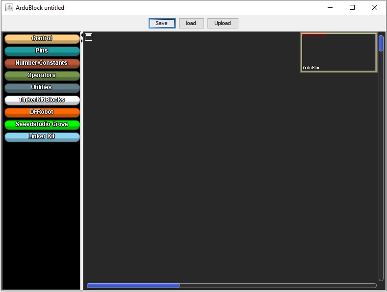
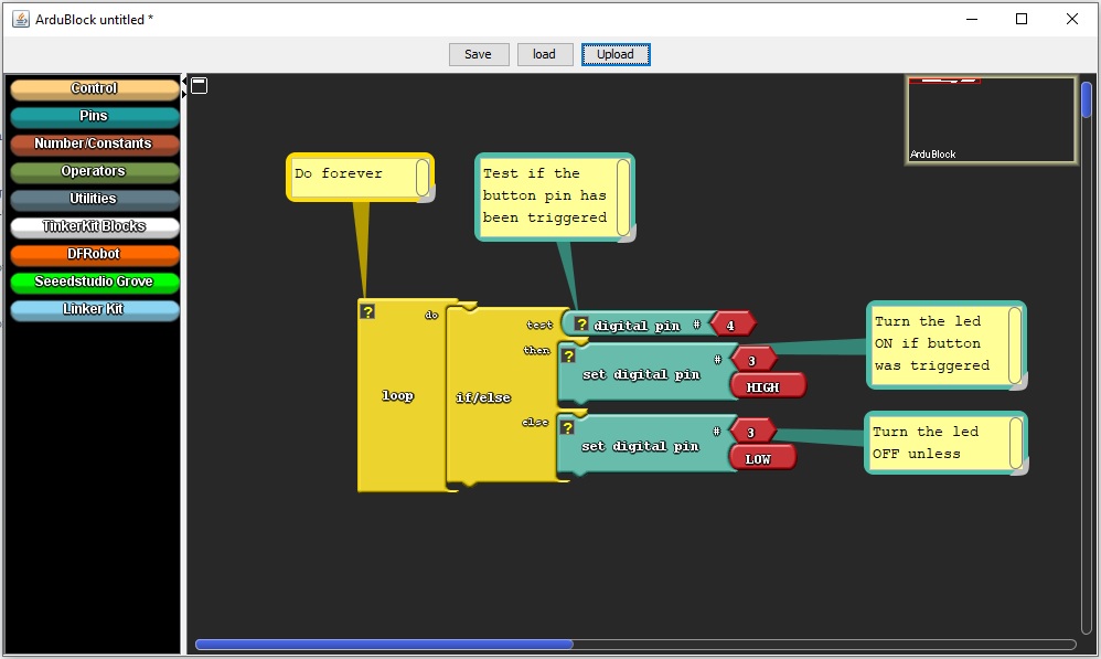
You simply "draw" your skecth with blocks and upload it to your board like you would normally do with normal text code, and the software will turn your diagram into real Arduino code before compiling it and sending it to the board.
This is how a simple led and button program will look like in Ardublock:
w08_program2.ino
The individual assignment is to read a microcontroller data sheet, program our board to do something and use as many programming languages and environments as possible.
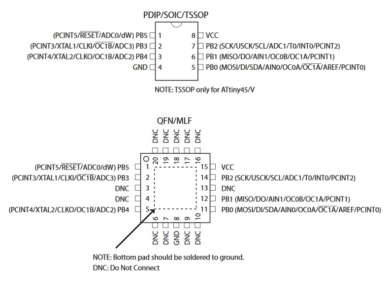
Microcontroller data sheet
As my board is based on the ATtiny45 microcontroller, I started by reading its data sheet and especially the I/O pins configuration:AVR programming with Arduino
A Arduino can be used as an In-System Programmer or ISP to program the AVR microcontroler on our board (ATtiny45 in my case).I followed both this tutorial and this other one to help me in the process.
An ISP allows AVR microcontrollers to be programmed without having to remove them from the board.
Six wires are needed to program an AVR microcontroller.
Three of these wires are for Serial Peripheral Interface (SPI) and are:
- Master In - Slave Out (MISO)
- Master Out - Slave In (MOSI)
- Serial ClocK (SCK)
The "Slave" is the AVR chip you want to program.
The other three wires are:
- 5V power supply (VCC)
- Ground (GND)
- Reset (RESET)
Preparation steps
I already have the Arduino IDE installed on my computer.It's needed in the process and can be downloaded here.
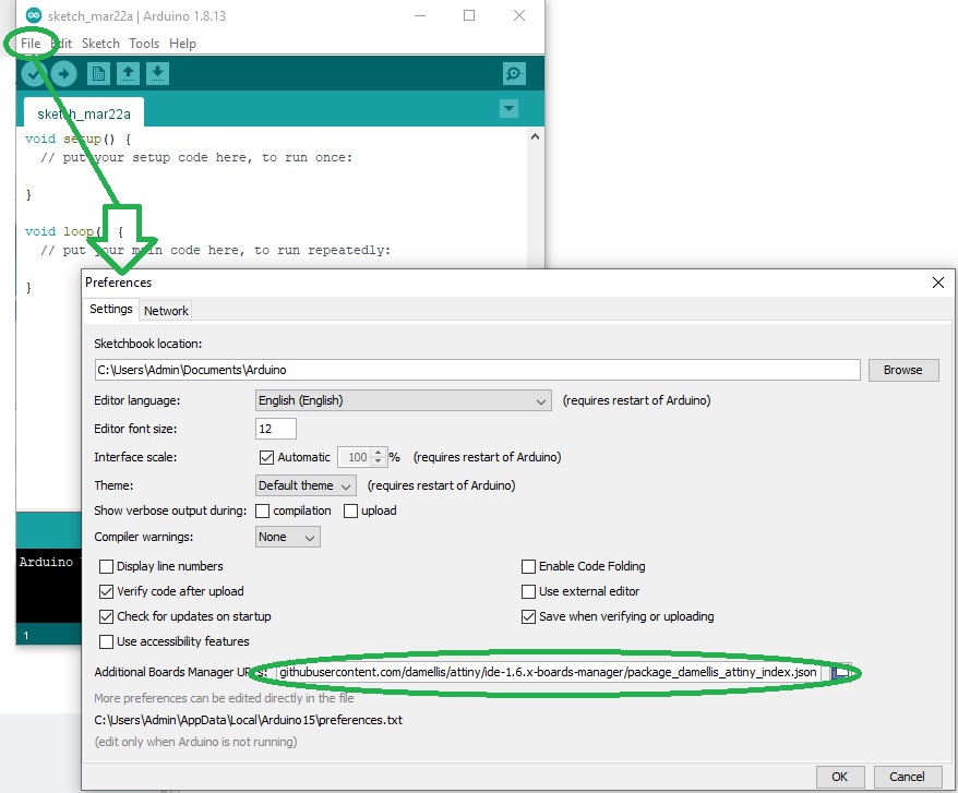
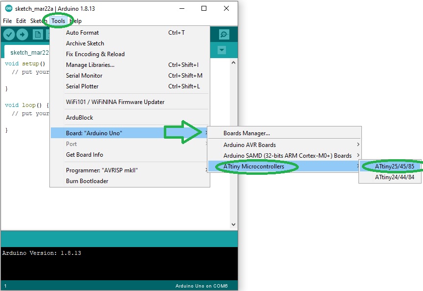
Once installed we first need to add support for the ATtiny in the Arduino IDE.
In
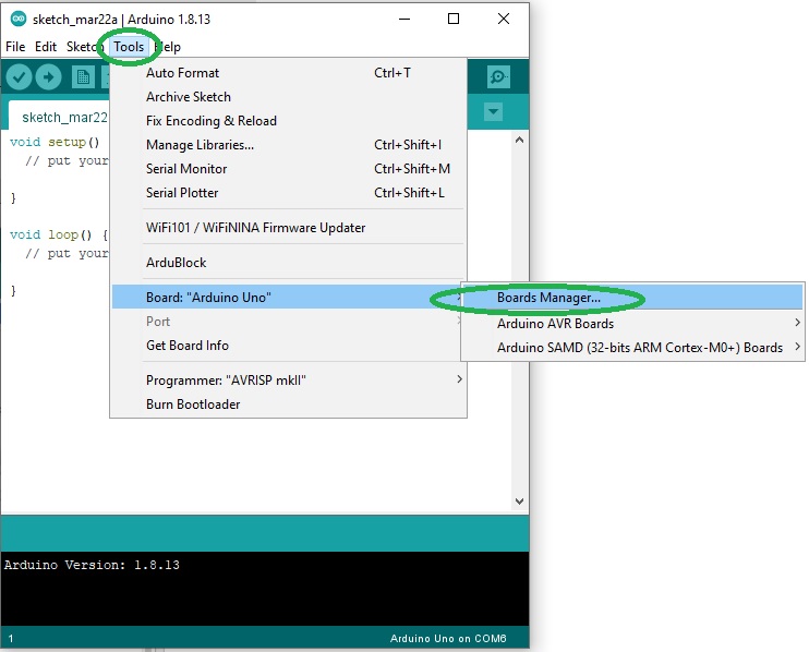
File > Preferences we must paste "https://raw.githubusercontent.com/damellis/attiny/ide-1.6.x-boards-manager/package_damellis_attiny_index.json" in the "Additional Boards Manager URLs" field and then click OK:Then if we go to
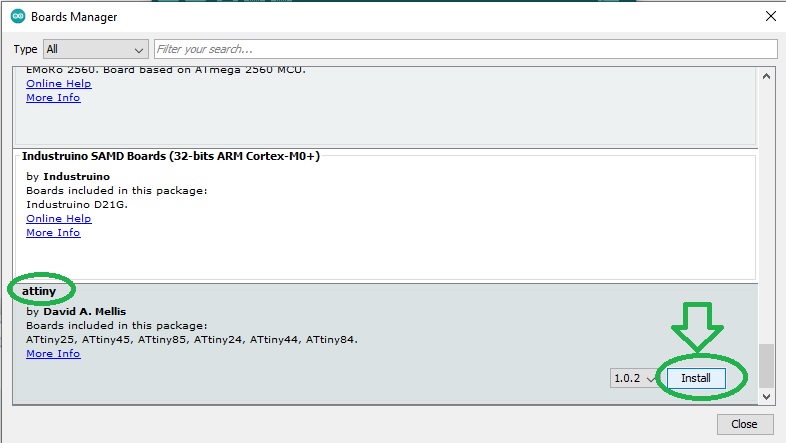
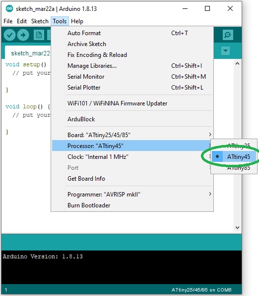
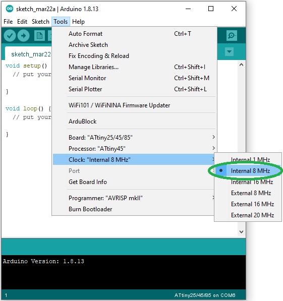
Tools > Board > Board Manager we will find attiny that we must install by clicking on the Install button:The ATtiny45 runs at 1MHz by default and if we want to make it run at 8MHz we need to burn the bootloader first by clicking on
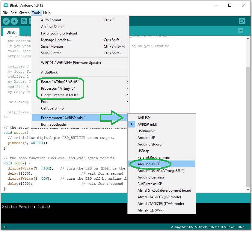
Tools > Burn Bootloader.Now we can turn the Arduino into an ISP by loading
File > Examples > ArduinoISP sketch onto it:Our Arduino Uno is now configured as an ISP programmer and we can use it to send code to the target AVR of our board:
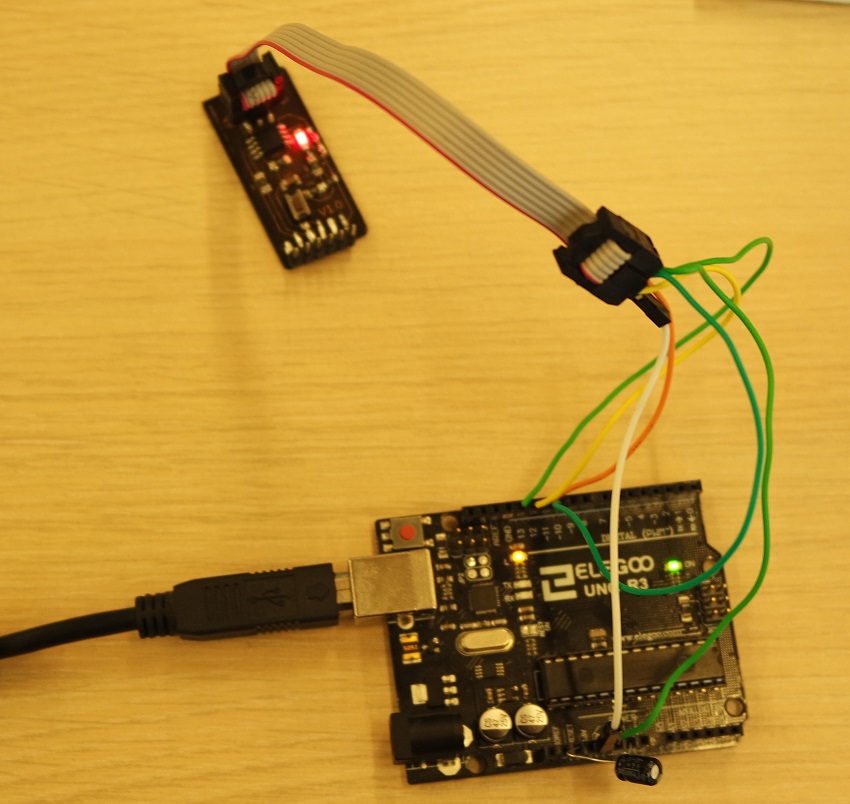
Now we need to connect our board to the Arduino and here is how everything is connected:
- Arduino pin 13 must be connected to SCK
- Arduino pin 12 must be connected to MISO
- Arduino pin 11 must be connected to MOSI
- Arduino pin 10 must be connected to RST (RESET)
- Arduino 5V must be connected to VCC
- Arduino GND must be connected to GND (GROUND)
Once everything is connected we can use the Arduino IDE to write code and load it into our AVR. First tested on an ATtiny45 fixed to a breadboard:
And then on my board:
Program writting
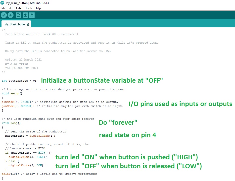
I first wrote a program to turn on the LED when the button is pushed on (and as long as it is), and turn it off when it's released:Code explained
Here are more details about the code.This first line of code creates an integer variable to store the current state of the button.
It's inserted before the setup function:
int buttonState = 0;Pins are configured inside the setup function with pinMode().
Pin 4 (the pushbutton) is set as an input and pin 3 (the LED) is set as an output:
void setup()

							{

								pinMode(4, INPUT);

								pinMode(3, OUTPUT);

							}
In the main loop the digitalRead() function is used to read the state of pin 4 which can be either HIGH (5V) or LOW (ground), and stores it in the buttonState variable:
void loop()

							{

								// read the state of the pushbutton

								buttonState = digitalRead(4);
Then there is an if statement to check if buttonState is HIGH.
If the condition is true, pin 3 (the LED) is set to HIGH (turned on) with digitalWrite().
Otherwise the code inside the else statement is executed and pin 3 (the LED) is set to LOW (turned off):
						// check if pushbutton is pressed.

						// if it is the button state is HIGH

						if (buttonState == HIGH) {

							digitalWrite(3, HIGH);

						} else {

							digitalWrite(3, LOW);

						}

						delay(10); // Delay a little bit to improve simulation performance

						}
Next I tested another one that turns on the led when the button is pushed once (and keeps it on), and turns it off when the button is pressed once again:
More on AVR programming
During the week-end I started reading a excellent book that Jonah adviced: "Make: AVR Programming" by Elliot Williams.It's very well explained and helped me a lot in understanding what was all this week about (and the next ones).
I hardly recommend it!
Here are the 2 first chapters that already teached me a lot!
While reading it, I started to think of another method using "regular" C programming and compiler. Unfortunately I wasn't able to finish testing that route because I've been missing time.
But following are the things that I started to do and to note down.
Toolchain installation
We want our board to do something so we need to tell it what we expect from it by programming it.That means we must somehow send some code we have written from our computer to the microcontroler on our board.
And this requires several tools:
- a text editor for writting the source code
- a compiler to turn the source code into machine code
- a uploader software and a hardware flash programmer to send machine code to the AVR
Text Editor
I will use Notepad++ to write and edit my source code.Compiler
The source code has to be compiled for the AVR by turning human readable C instructions into AVR understandable machine code.The compiler we've been using so far in the previous electronic weeks is
avr-gcc.
Flash programmer
The compiled machine code has to be sent to the chip and stored into its flash memory.A flash programmer needs to be connected between the source computer and the target AVR microcontroller.
It could be either the ATMELice we have at our lab, the FABtinyISP we made on week 4, or an Arduino board.
Software uploader
A software uploader is needed to send the machine code to the flash programmer. For this task I will use AVRDUDE.Under Windows OS the toolchain can be installed by installing WinAVR.
Programming the board
What do I want my board to do?Planning ahead is the very 1st step before getting into writing source code.
The board we made on week 6 has a push button and a led that could be used has an input and output to light lhe led when the button is pushed down for example.
Source code writting
The source code is written in AVR C language and needs to follow a certain structure.This is the structure of a typical AVR C code:
In the preamble section you can include pieces of code from other source files, define variables and functions.
Then comes the
main() function which is mandatory. It's the entry point where the AVR will start executing the code when powered on.while(1) is a forever loop that will keep running as long as the microcontroller is powered on.It's inside that loop that we must put our instructions and tell the AVR what to do (like blinking a led for example).
Blinking LED program example:
I want the LED on my board to only light up when the button will be pushed down.
The led on my board is connected to PB3 and the push button to PB4.
By default DDRB (Data Direction Register B) pins are all set to zero which means they are configured as inputs.
I want to configure them all as outputs except for my button that's connected to PB4:
DDRB = 0b11101111; //set PortB to all outputs except PB4My LED being on PB3, in the main loop the code that will turn it on or off now becomes:
PORTB = 0b11101111); /* Turn on 3rd bit/pin in PORTB */
PORTB = 0b11100111); /* Turn off 3rd bit/pin in PORTB */I need to turn the led on only when the push button is pressed down so I need to read its state.
My push button being connected to PB4, I need to know if the value of the fourth pin of the PINB register has changed (PB4).
Testing a bit state can be done with a AND logical operator and a bitmask because an AND operator will only return 1 if both bits are 1.
So by using a bitmask (with a 1 in bit four) and a AND logical boolean, I can test if it returns zero (false) or anything else (true).
This is how to set a bitmask with a 1 in bit four:
(1 << 4) which is the same as storing 00001000.A AND logical boolean between our bitmask byte and the input register PINB will return something else than zero (true) if the pin 4 of our input register has been set. Therefore we can simply test:
Like I said above, I've been missing time to explore that route better...
Last year assignment
And finally this is the assignments I've been doing last year while we were under COVID lockdown (I'm a continuing student from 2020).TEXT FROM 2020 COVID LOCKDOWN
Unfortunately the board I had planned isn't finished and as I can't go back to our Fablab, I used an Arduino board instead for getting used to write some code. The board is a Mega 2560.
But before to start coding, we must first connect everything to the Arduino.
The initial board needed to have a push button and a LED. So I will need these to also be connected on the Arduino.
TinkerCAD
Tinkercad Circuits is a free browser-based program that lets you build and simulate circuits.Before to physically connect my components to the Arduino, I planned everything on Tinkercad just to make sure and not taking the risk to fry anything.
I started by adding an Arduino Uno board and a small breadboard by dragging them from the components panel (on the right) to the workplane.
Then I connected the Arduino 5V to the breadboard power (+) and the Arduino ground (GND) to the ground rail (-) by creating colored wires.
In the same way I connected the power and ground rails to their respective buses on the opposite side of the breadboard with a red wire (power) and a black wire (ground).
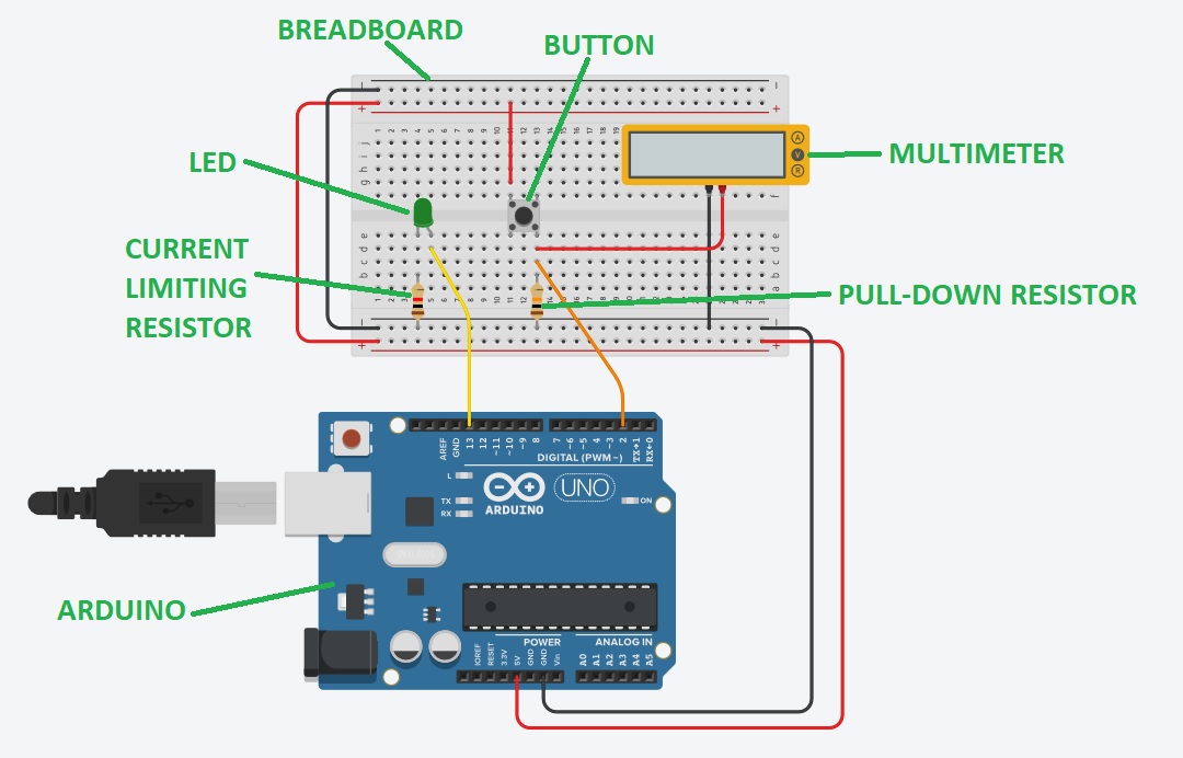
A LED and a 1K Ohms resistor are also added. The LED is plugged into two different rows with the cathode (negative, short leg) connected to one leg of the resistor.
The orientation of the resistor isn't important because resistors are not polarized but it's not the case for the LED.
The other leg of the resistor is connected to ground, and the LED anode (positive, long leg) is connected to the Arduino pin 13.
A pushbutton is needed to trigger the LED so I added one in the center of the breadboard (column break) and connected one button leg to power, and the diagonally opposite leg to pin 2.
I also added a high value resistor (10K Ohms) between that same button leg and the ground to act as a "pull-down" and a multimeter between Arduino pin 2 and ground.
This is my final circuit:
And here is another version without a breadboard that is easier to understand:
Programming
Then I wrote a small programm to turn on the LED when the button is pushed on (and as long as it is), and turn it off when it's released:This code is copy/pasted in TinkerCAD's place for "Code" and a simulation is launched ("Start simulation"). The signal being seen by pin 2 is displayed on the multimeter:
Code explained
Here are more details about the code.This first line of code creates an integer variable to store the current state of the button.
It's inserted before the setup function:
int buttonState = 0;Pins are configured inside the setup function with pinMode().
Pin 2 (the pushbutton) is set as an input and pin 13 (the LED) is set as an output:
void setup()

							{

								pinMode(2, INPUT);

								pinMode(13, OUTPUT);

							}
In the main loop the digitalRead() function is used to read the state of pin 2 which can be either HIGH (5V) or LOW (ground), and stores it in the buttonState variable:
void loop()

							{

								// read the state of the pushbutton

								buttonState = digitalRead(2);
Then there is an if statement to check if buttonState is HIGH.
If the condition is true, pin 13 (the LED) is set to HIGH (turned on) with digitalWrite().
Otherwise the code inside the else statement is executed and pin 13 (the LED) is set to LOW (turned off):
						// check if pushbutton is pressed. if it is, the

						// button state is HIGH

						if (buttonState == HIGH) {

							digitalWrite(13, HIGH);

						} else {

							digitalWrite(13, LOW);

						}

						delay(10); // Delay a little bit to improve simulation performance

						}
Doing it for real
The TinkerCAD simulation is working well so I physicaly connected everything the same way, compiled the program with the Arduino IDE and uploaded it on the Arduino card:I also wrote another small program to play sounds on a buzzer but this time I used a Arduino Uno:
Ardublock testing
Ardublock is an open-source visual programming language that enable visual programming for the Arduino.It makes programming more intuitive without the annoyance of syntax error and lets you better focus on the program's tasks.
Installing Ardublock on Windows OS
First download Ardublock and place the downloaded .jar file in Arduino's Sketchbook location.An easy way to locate it on your computer is to launch the Arduino IDE, go into the "Preferences" menu and copy the Sketchbook location:
Then launch an "Execute" command by pressing "Windows + r" / "cmd" + Enter and paste the previously copied path here then press "Enter":
Once at the correct location, you have to create a "tools" directory, another "ArduBlockTool" directory within it, and finally another "tool" directory within the previous one and paste the previously downloaded .jar file here:
You can then relaunch Arduino IDE and check that Ardublock now appears under the "Tool" menu:
Coding with Ardublock
Now that you have Ardublock in your Arduino IDE, coding becomes as easy as drag-and-drop.You simply "draw" your skecth with blocks and upload it to your board like you would normally do with normal text code, and the software will turn your diagram into real Arduino code before compiling it and sending it to the board.
This is how a simple led and button program will look like in Ardublock:
Files for this week
My_Blink_button.inow08_program2.ino