Final Project
What will it do?
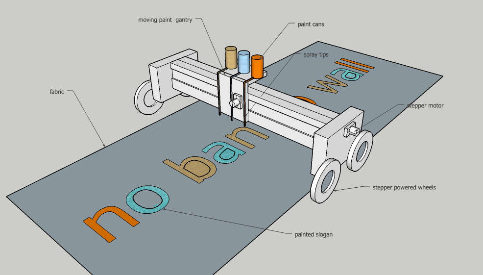
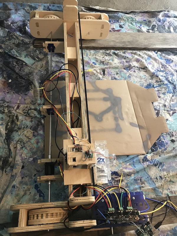
My plan is to build a cnc banner painter that is self propelled. There will be a limited y axis of movement along a gantry, and a unlimited travel limit on the x axis. The system will use spray cans to apply paint.
Who’s done what beforehand?
My inspiration for this project is a project by the Institute for Applied Autonomy This project is a remote controlled car with a dot matrix spray system.
During my final presention someone mention this project a great example of early 2000s dot matrix fun!
What will you design?
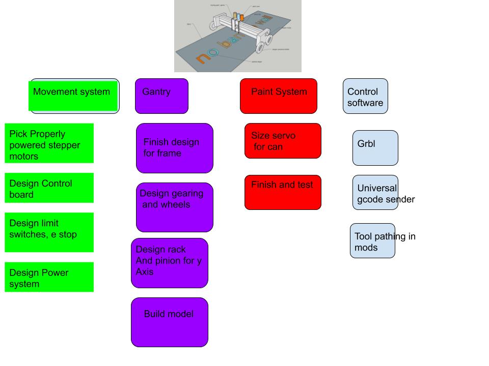
The project will consist of
- Control software
- Control system
- spray system
- gantry for Y axis
- rolling system for X axis
What materials and components will be used?
the frame will be made out of plywood cut on the CNC router. It will have bushing cutouts for the wheels, and a rack will be milled into the top for a pinion on the y axis. two sets of guides and bearings will allow for smooth movement of the y axis.
The Y gantry will have 3 holders for spray paint with a servo on each. these will clip in with magnets to allow for easy change over.
The wheels for the X axis will be made out of three pieces of plywood cut on the CNC. The two outer pieces will be wrapped in rubber, while the inside piece will be geared. This will allow the option to lay a track down for more precise registration. There will be two stepper motors for this axis, one on each side of the gantry for each wheel set.
The power and control computer will be external with a cable running to a controller board. The design software will offset for different colors.
The control board will be based on systems developed for tinyg or smoothieware
Designing these boards will be one of the major goals for this project. Documentation from this student have been helpful.
http://mtm.cba.mit.edu/control/simplestep/makeit.html
http://mtm.cba.mit.edu/machines/stages/
Where will come from?
Most of the materials for this project can be purchased locally or will be the part of the fab inventory. The parts and materials that will need to be ordered are listed below.
Supplies to be ordered
| Qty | Description | Price | Link | Notes |
|---|---|---|---|---|
| 3 | stepper motors nema 23 | $23.99$ | https://www.amazon.com/STEPPERONLINE-Stepper-178-5oz-1-26Nm-Stepping/dp/B00PNEPF5I/ref=sr_1_2?crid=3PGXA6M4Z0I09&dchild=1&keywords=nema+23+stepper+motor&qid=1586714847&sprefix=nema+2%2Caps%2C161&sr=8-2 | Order many |
| 1 | servos Arduino kit | $20.99$ | https://www.amazon.com/Control-Angle180-Digital-Torque-Helicopter/dp/B07NQJ1VZ2/ref=sr_1_7?dchild=1&keywords=servo&qid=1586714960&sr=8-7 | |
| 1 | 3/4 mdo plywood | 69.00 $ | https://www.boulterplywood.com/ | |
| 1 | 1 sheet of 1/2 mdo plywood | 89.00 $ | https://www.boulterplywood.com/ | |
| 3 | Atmel ATxmega192 | 6.00 $ | https://www.digikey.com/product-detail/en/microchip-technology/ATXMEGA192A3U-AUR/ATXMEGA192A3U-AURTR-ND/3678723 | |
| 9 | TI DRV8818 | 1.79 $ | https://www.digikey.com/product-detail/en/texas-instruments/DRV8818PWPR/296-31642-2-ND/3045978 | |
| 1 | spray paint rattle cans | 8.00 $ | http://amazon.com/test |
How much will they cost?
around 280$
What parts and systems will be made?
my intention is to make everything besides the motors, power supplies, and the laptop used for control
What processes will be used?
The boards will be laser etched on the fiber laser. The controllers will be reflow soldered. The gantry and gears will be milled on the CNC router. The mounts for spray paint will be laser cut with a 3d printed actuator.
What questions need to be answered?
My major question is finding an effective control board system that can be rapidly fabricated and is scalable. I would like to walk away from this project with a system for cnc automation that can be used for other projects.
How will it be evaluated?
A working banner painter will be standard for this project. Workable accuracy, and a stable system for designing and rapidly fabricating banners.
Motor Choice
After researching and learning about motion control systems as well as consulting my instructors I decided to move away from stepper motors and look into using brushless DC motors with an encoder. One of the major advantages will be the potential speed increase. Since this is a machine that doesn’t require extreme precision I figured there may be advantages to not using stepper motors. However when doing some more research I found that there we’re BLDC motor control systems that could produce extremely accurate positioning.
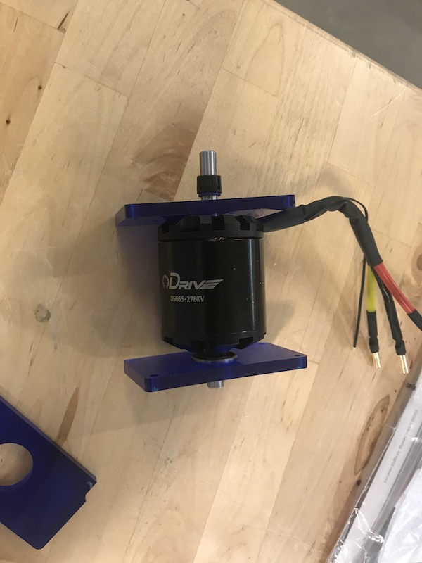
I watched several videos and started reading about the odrive it seemed like an interesting option as an open source board. I also researched the other options listed on the Machines That Make page on BLDC Though all of them seemed like good options, I had the same concerns about all of the boards, fabrication. Most of the examples I saw were made at a board house, including the impressive atkbldcdriver. As much as I would love to pursue fabricating one of these, I figured I should ask about incorporating an odrive into the project. I asked in an issue and got an ok from Neil and Greg for using an odrive as long as it is paired with a fabricated board. I hope that this will work well! Cost will be something of an issue. The board is going to cost over 120, along with three motors and encoders. One useful things is that the drive has a motor casing file that I can incorporate directly into the design.
Design Updates
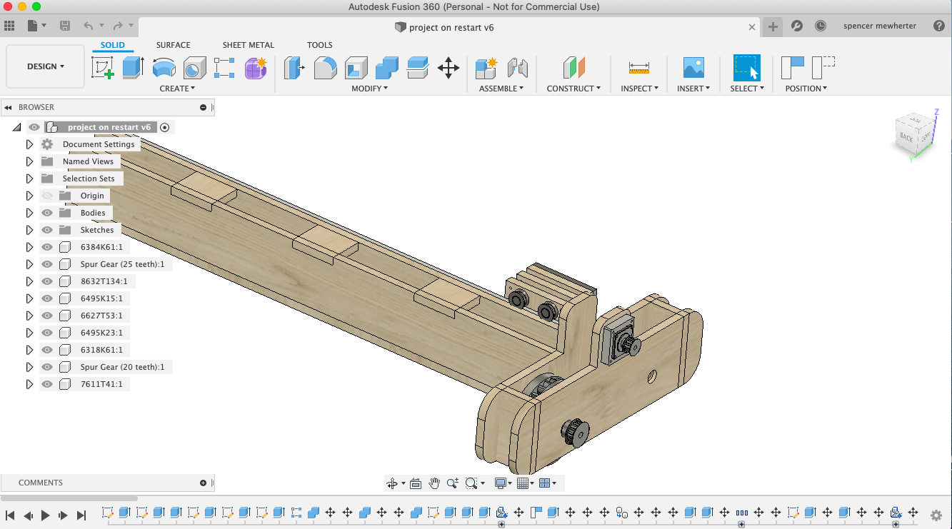
I redrew the design from scratch. There are two major alterations I make to the design. I decided to make the wheels out of three pieces of plywood with a gear cut into the middle piece. these are not for the connection to the motors, but are for the potential of running the machine on a long plywood rack to allow for faster movements without worrying about loss of traction. I plan to develop two modes of operation; a low speed setting running on the ground on wheels, and a high speed mode running on a geared track.
Spray Paint System
fabricating and configuring the spray paint system is documented in output week
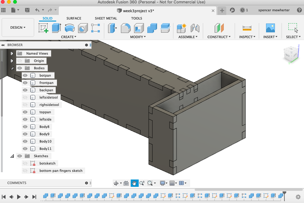
Gantry Fabrication
Fabricating the gantry is documented in the CNC milling week
Putting Things Together
Two factors that are important in my machine is speed and accurate position control. I want a speedy and efficient banner printer, and I want it to be able to work in less then ideal conditions (out of level, rough surfaces, etc). Considering these factors I decided not to use a typical stepper control system and use encoded brushless dc motors for my two axis.
The idea behind this control system is to have the speed and accuracy of an industrial servo for way less money. To achieve this, there need to be a board to power the motor and process the feedback from a rotary encoder. The Odrive can process step/dir data which I’m going to produce with a board running GRBL paired with universal Gcode sender
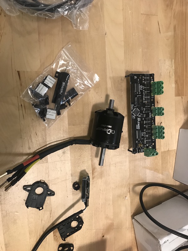
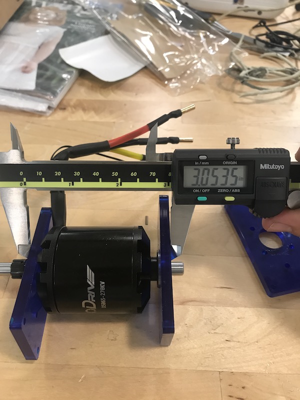
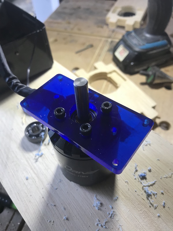
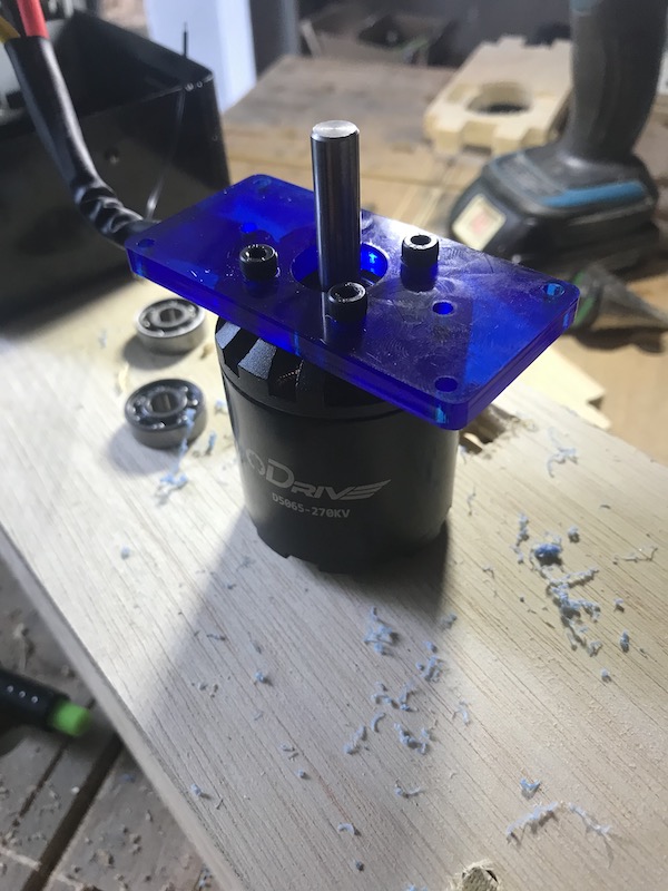
First I opened up the motors i ordered and took some measurements for mounting plates.
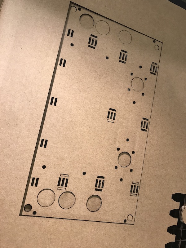
I laser cut a cardboard template to check the bolt positions.
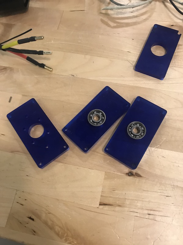
These laser cut plates screw into the motor and also give a space for the encoder to be mounted
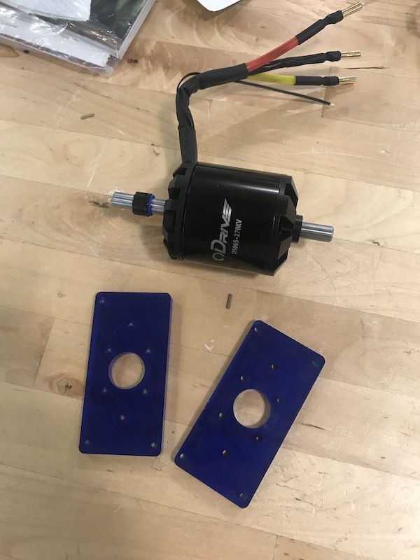
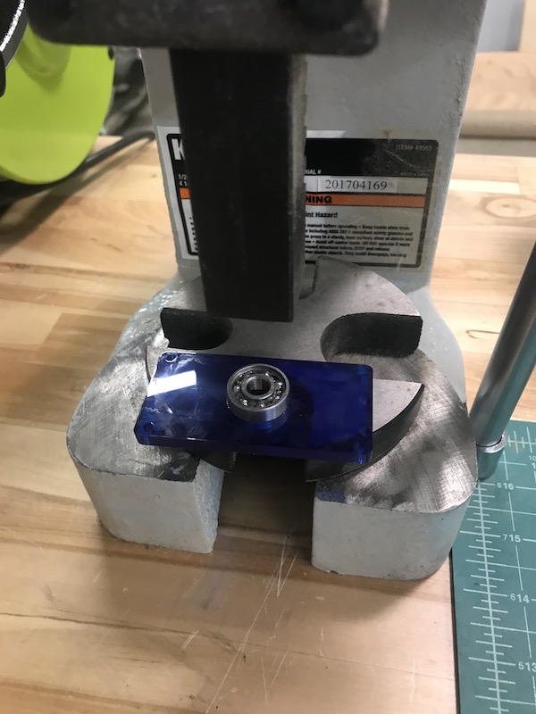
I also made a plate to hold a 8mm bearing to hold the shaft
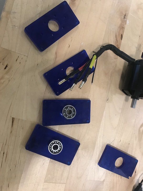
After a couple of tries I got press fits I was happy with
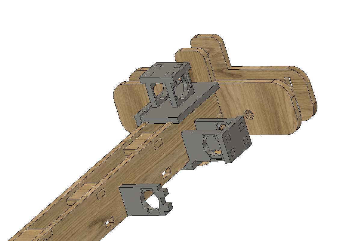
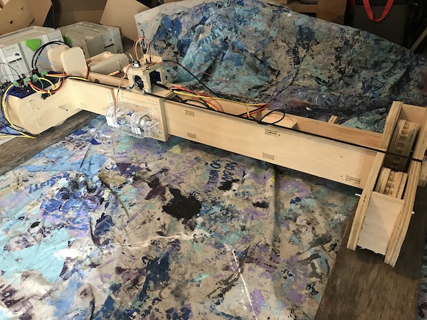
complete set of motor mounts and bearings
on the motor, the black plastic piece on the shaft attaches to the encoder
 the encoder and motor mount. with this measurement I can finish designing the motor mounts for the frame.
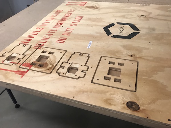
cutting out the motor mount prototype
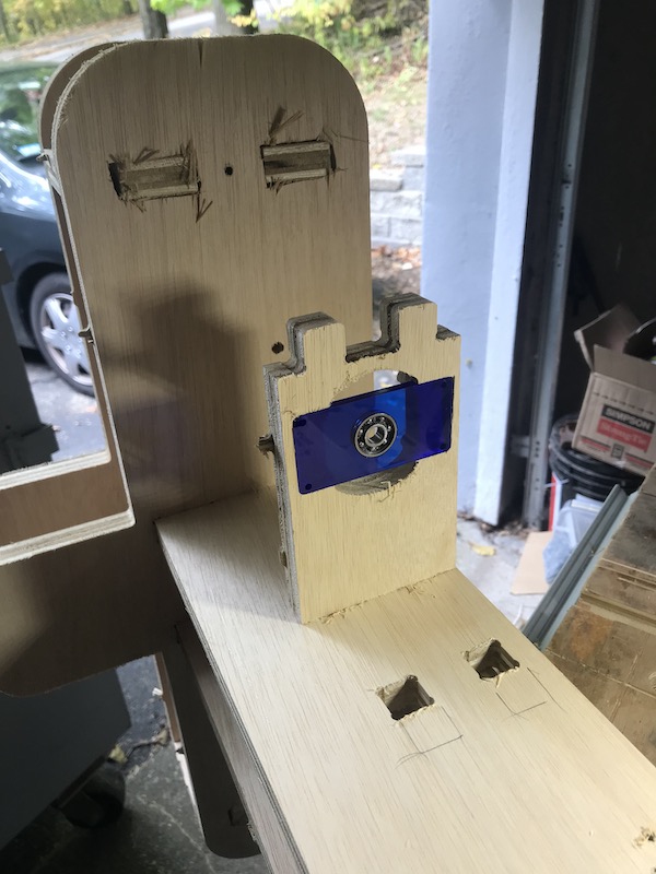
setting the bearings into the gantry
all bolted up! these need to carry all of the torque of the machine moving
The 8mm shaft with flex attachments
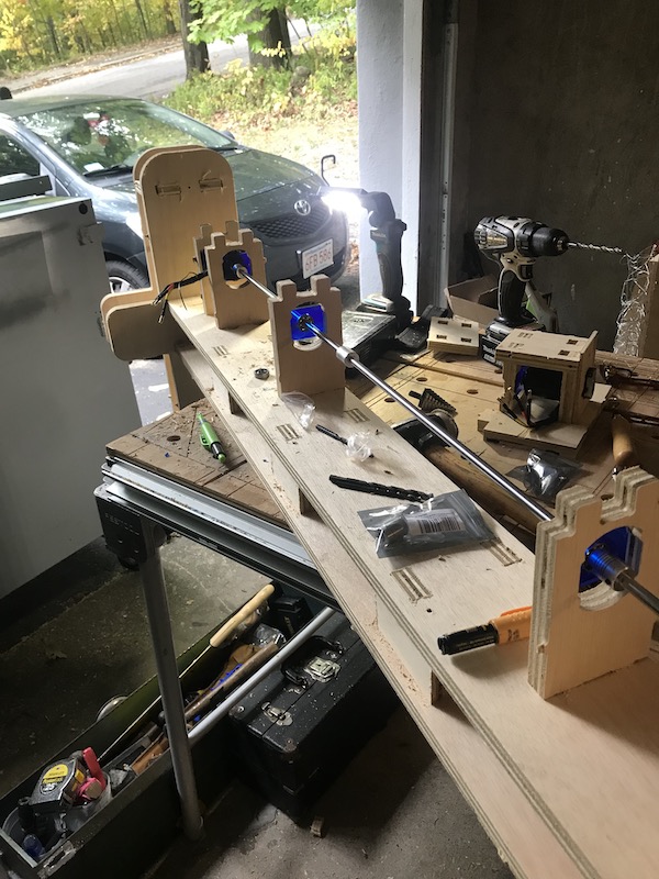
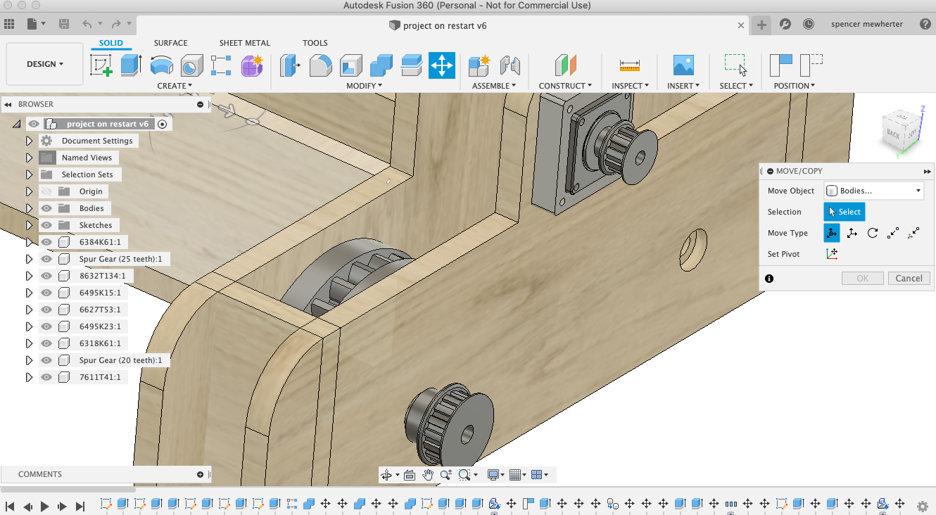
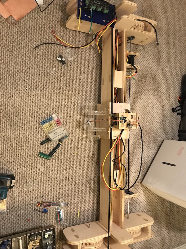
assembling the y axis carriage
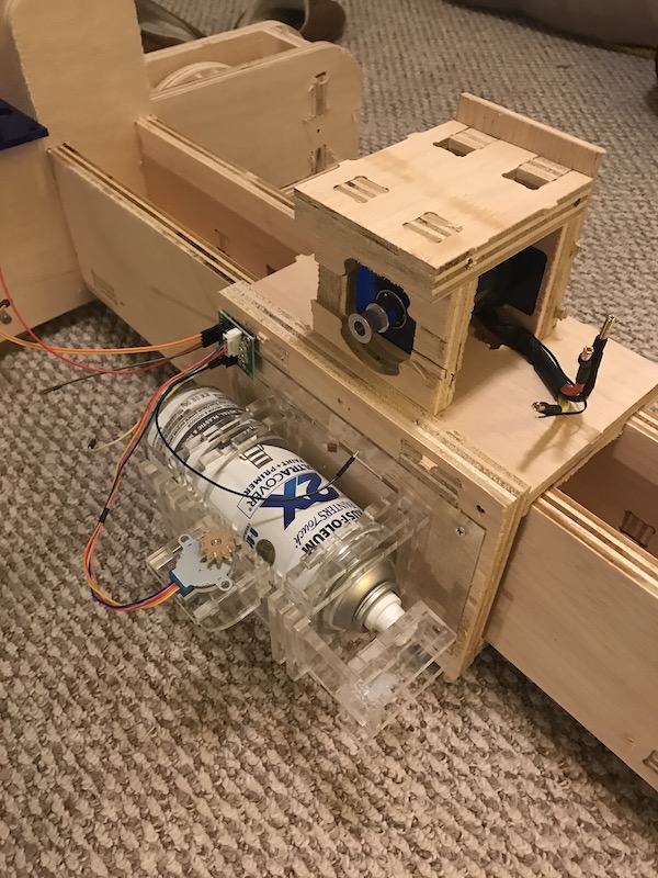
Odrive mounted to the electronics plate. the holes and slots are for routing wires and zip ties.
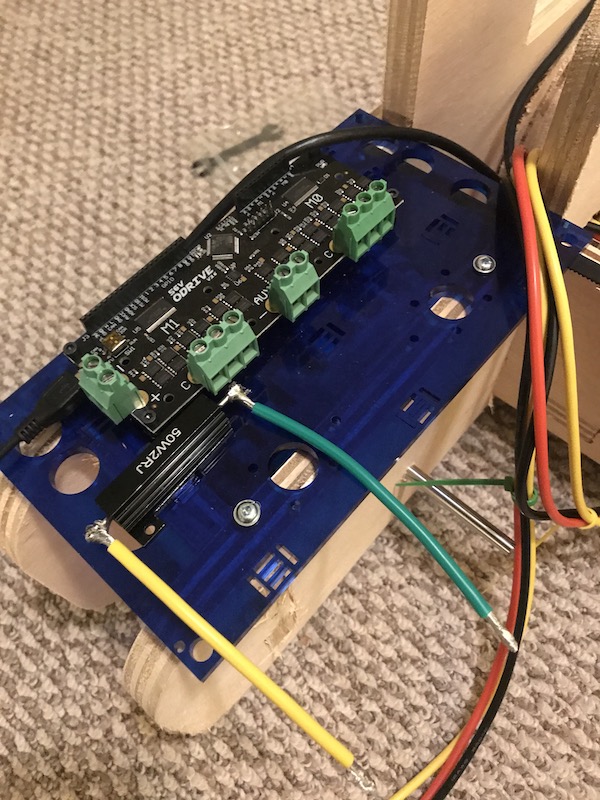
Wiring detail, the two motors (M1 and M0) are wired with 3phase. The AUX is wired to a resistor for breaking.
overview of the wiring process
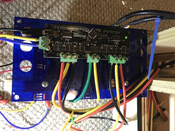
the odrive board wired up
Getting Started With Odrive
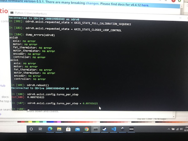
Time to power up and configure the Odrive! Fortunately the documentation for the odrive is pretty clear if a little sparse. All the configuration is done in odrivetool, a python command line tool for configuring the board and running commands. First I needed to update the firmware on the board to the latest version, since this an active project a lot changes so updating was important. I was running windows for this configuration process so I used the standalone anaconda install.
pip install --upgrade odrive
command to install odrivetool
I then run these commands to set up the odrive to my particular setup. this includes the information for both my for my motors and encoders.
The documentation goes into more detail about these settings. I leave the defaults for speed and max amps for this initial testing phase
 odrv0.config.brake_resistance = 2
odrv0.axis0.motor.config.pole_pairs = 7
odrv0.axis0.motor.config.torque_constant = .03
odrv0.axis0.motor.config.motor_type = MOTOR_TYPE_HIGH_CURRENT
odrv0.axis0.encoder.config.cpr = 8192

odrv0.axis1.motor.config.pole_pairs = 7
odrv0.axis1.motor.config.torque_constant = .03
odrv0.axis1.motor.config.motor_type = MOTOR_TYPE_HIGH_CURRENT
odrv0.axis1.encoder.config.cpr = 8192

odrv0.save_configuration()
After saving I reboot the odrive using this command
odrv0.reboot()
I am now ready to run the motors through their calibration process. I make sure there isn’t too much load on the motors before running this step.
odrv0.axis0.requested_state = AXIS_STATE_FULL_CALIBRATION_SEQUENCE
With this the motors will beep, then rotate to match the amperage of the motor with the counts on the encoder.
I can then put the motor into run position to do this I run
odrv0.axis0.requested_state = AXIS_STATE_CLOSED_LOOP_CONTROL
this holds the position of the motor and sets it in a closed loop control. It is now ready to receive commands
Configuring GRBL and STEP/DIR with odrive
The next step is to set the odrive to receive information from grbl. To do this I need to set it in the proper control mode. Following the documentation was pretty clear, first i needed to disable UART to free up the pins needed to control axis0/X
odrv0.config.enable_uart = False
Remember that all of this is in Python! Case matters! Second I turn on STEP/DIR mode for both my axis
odrv0.axis0.config.enable_step_dir = True
odrv0.axis1.config.enable_step_dir = True
Now I wire up my GRBL board to the Odrive consulting the two relevant pinouts for Odrive and GRBL Importantly I also connect the ground on both boards and make sure the my wires are routed to avoid interference with the motor cables. I failed to connect the ground properly at first and had extremely unpredictable motor movements.
OK! Now I should be set to try and run Gcode commands using Universal Code senders. I open up the proper port to communicate with my GRBL controller and jog the 2 axis! They both work!
Control Tree
inkscape to generate vector files and Gcode
exampleFile.nc
Universal Gcode sender to read file and send commands
GRBL on arduino uno read commands from universal gcode sender and outputs step/dir pulses
Odrive reads step/dir and uses a pid loop to control dc motors based on feedback from rotary encoders on each axis
Fabricated board receives pluse from arduino and triggers spray can with stepper motor.
Odrive Tuning
The challenge with my project is getting all of these elements working together and properly tuned, while powerful and very fast the motors and odrive are prone to overshooting and feed backing on themselves. I carefully tuned them via the instructions in their documentation. One issue I have is since I have several flex connectors in my shaft powering a pretty heavy gantry there is considerable spring force in my X axis. This was causing issues where the motors were unable to compensate. I addressed this by adjusting the gain lower than the default.
<axis>.controller.config.pos_gain = 20.0
while I got the machine moving in a less erratic way, I think a future loop would be to add a gear reduction on the x axis to address some of these issues. One thing I didn’t plan for was that even though my motors are powerful enough to move the gantry quickly they are still limited by their braking force.
GRBL tuning
One setting that helped was adjusting down the ramp up and down settings in GRBL. I also needed to adjust the scale factor on each axis to represent the mm per step. Since I didn’t have hard numbers for this I manually stepped them and measured the amount of movement on each axis. I found this video helpful for tuning GRBL. Here is my finished table of GRBL configurations.
    >>> $$

    $0 = 10    (step pulse, usec)

    $1 = 25    (step idle delay, msec)

    $2 = 0    (step port invert mask:00000000)

    $3 = 0    (dir port invert mask:00000000)

    $4 = 0    (step enable invert, bool)

    $5 = 0    (limit pins invert, bool)

    $6 = 0    (probe pin invert, bool)

    $10 = 3    (status report mask:00000011)

    $11 = 0.010    (junction deviation, mm)

    $12 = 0.002    (arc tolerance, mm)

    $13 = 0    (report inches, bool)

    $20 = 0    (soft limits, bool)

    $21 = 0    (hard limits, bool)

    $22 = 0    (homing cycle, bool)

    $23 = 0    (homing dir invert mask:00000000)

    $24 = 25.000    (homing feed, mm/min)

    $25 = 500.000    (homing seek, mm/min)

    $26 = 250    (homing debounce, msec)

    $27 = 1.000    (homing pull-off, mm)

    $100 = 17.850    (x, step/mm)

    $101 = 27.770    (y, step/mm)

    $102 = 250.000    (z, step/mm)

    $110 = 500.000    (x max rate, mm/min)

    $111 = 500.000    (y max rate, mm/min)

    $112 = 500.000    (z max rate, mm/min)

    $120 = 10.000    (x accel, mm/sec^2)

    $121 = 10.000    (y accel, mm/sec^2)

    $122 = 10.000    (z accel, mm/sec^2)

    $130 = 200.000    (x max travel, mm)

    $131 = 200.000    (y max travel, mm)

    $132 = 200.000    (z max travel, mm)
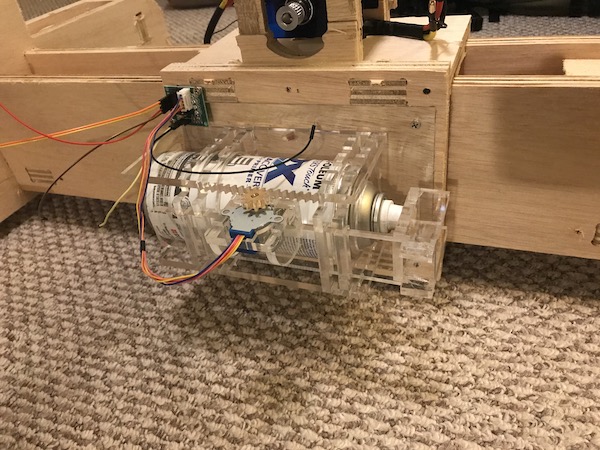
Spray Can system
Fabricating the PCB and motor assembly is documented in output week interestingly I found that different spray cans require pretty different pressing force to trigger. For some of them I found that a bit of preload with a rubber band was helpful. A future loop would be to use a higher torque motor or a sensor to improve this action.
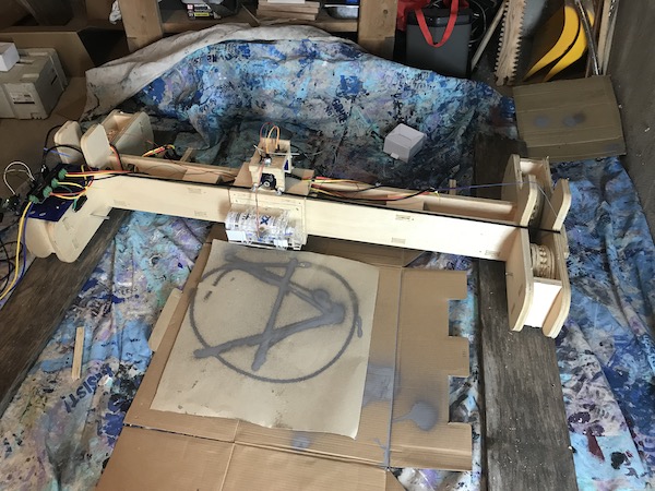
Running the Machine
I now have all of my elements working independently, time to find if it can successfully run a Gcode file to print a design. I make a simple test circle (A) vector file and run it though my tool chain!
Inkscape
I’ve been using inkscape for a long time. While I generally use illustrator for most graphical design work I often still fall back to inkscape for 2D CNC applications. I drew a simple (a) and scaled it to the correct size. I then converted all my shapes to paths. I also increased mine line size to .5mm. This is unusually thick compared to what I will typically use for a laser cut, this is due to some unusual issues I had with JScut outlined below. I then saved as SVG, insuring that I didn’t have any scale factors.
JSCUT
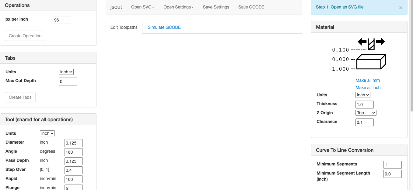
Since I wanted all of my programs to be free and open source I decided to try (JSCUT](http://jscut.org) a web app based Gcode editor. While not the smoothest application I’ve used it definitely did the trick! One of the unusual things is that all the settings files need to be saved locally to ensure that they work. I opened my SVG file I created from Inkscape, I set the program to read 96 pixels per inch. One thing I learned from this program is that inkscape SVGs scale to 96 pix per in, while adobe illustrator uses 72. I’m very used to having issues with scale, so it was good to have a ghearer understanding of why these occur. I made sure to double check the size of the vectors before exporting Gcode. One issue | had was that it was really hard to select the vector lines. I read an issue from the developer that the hit detection used was somewhat problematic. I found that increasing line weight and then clicking slightly above the line did the trick. I could then select the engrave operation, set my feed rate and plunge rate. I use the plunge on Z rate to trigger the spray system so it is important that there is a value there. Even though it doesn’t directly control a motor. I set it to be the same as my feedrate and to cut to 6mm. This was a sufficient pulse to trigger the spray can board. I can then save my .gcode file after picking the desired offsets, checking the scale and previewing the visualization. Overall I’m impressed by what a simple web browser based code generator was capable of. However for the future of this project I would like to simplify this setup process to a single “make code for this vector’ button.
Universal Gcode Sender
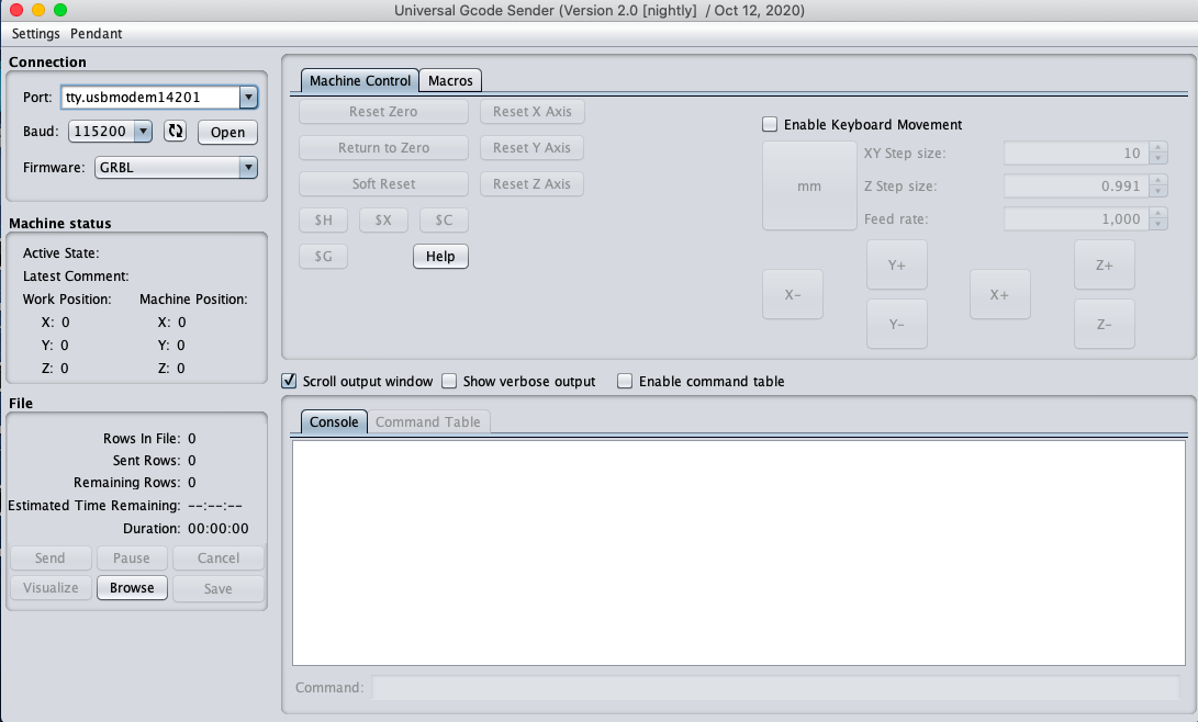 I can then load my file into the (Universal Gcode Sender (UGS)]
(winder.github.io). I have used this program for playing around with GRBL
and some stepper motors so I have some familiarity with it. I ended up
using there more basic version since I felt like I had such simple needs and
I was interested in trying it. The only functions I used in this programs
were; to jog the machine to check that the drives were stable and to test
feedrates, homing the machine, configuring GRBL parameters, and
sending .Gcode files. Overall I find UGS comparable to a lot of machines
controllers, fewer featured and glam that a lot of them, but far more stable
than the controller for Shopbot or many laser cutters. Overall this aspect
of the project was one of the smoothest. Connecting to the GRBL board
was easy.
I can then load my file into the (Universal Gcode Sender (UGS)]
(winder.github.io). I have used this program for playing around with GRBL
and some stepper motors so I have some familiarity with it. I ended up
using there more basic version since I felt like I had such simple needs and
I was interested in trying it. The only functions I used in this programs
were; to jog the machine to check that the drives were stable and to test
feedrates, homing the machine, configuring GRBL parameters, and
sending .Gcode files. Overall I find UGS comparable to a lot of machines
controllers, fewer featured and glam that a lot of them, but far more stable
than the controller for Shopbot or many laser cutters. Overall this aspect
of the project was one of the smoothest. Connecting to the GRBL board
was easy.
Running Tests
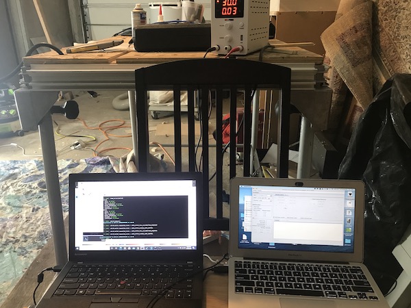
After some back and forth between the three programs above I ended up with a file that I was happy with. I started by running the machine blocked up off of the x axis wheels so I could observe the code running with out worrying about the machine running away from me. I could also easily reset the odrive if there were any issues with it. My setup is one laptop running the odrivetool and reading documentation and my mac laptop running my toolchain an gcode sender. This is kind of an awkward setup! but it does give me good ideas for moving forward. A bluetooth remote controlling an onboard raspberry pi sounds really dreamy. Once I confirmed that i could run my file with out crashing the y axis and that the spray system triggered I then started dry runs. I simply unplugged the spray boards signal line so I could run it without wasting paint or making a mess.
Trouble Shooting
Issues were plentiful, so I decided to break them down by axis. I’m lucky that I have a lot of control over each axis parameters across all of my systems. Addressing these issues was a combination of altering the machine, odrive parameters, and GRBL settings.
X Axis Issues
One of my major design issues is that I have too much of a spring load on my x axis shaft the result of this is that there is often stuttering movement along that axis, and also the potential for runaway feedback where the machine looses control and overspeeds. I’m happy that there are good ways to set speed limits per each axis in Odrivetool. I set the max speed for x axis at 1 rotation per second. I also tuned the PID loop gain parameters to address some of the overshoot and runway issues. I also adjusted the acceleration rate on the GRBL control for this axis. All of these settings were reached after lots of testing and failures. Tuning this axis was one of the most time consuming parts of this project. Though I’m glad how far I got with introducing stability to this axis and getting it workable, some mechanical alterations in the form of a gear reduction would definitely be very helpful. I’m planning to add this to my next iteration.
Y Axis Issues
starting off my y axis is far simpler and more conventional then my x axis. since it runs on a timing belt I was impressed by how simple getting this axis tuned was. Once I got my steps per MM figured out and my max feed rate determined (though my feedrate is limited by the x axis) it was pretty easy to move it around. One major issue I had was the axis pinching on wires. I added a rubber cable tensioner that helped a lot but I’m not happy with that solution. For my next iteration I want to make a laser cut cable carrier to run along with this axis. When I was first designing this machine and budgeting for materials I rejected commercial cable systems as too expensive and forgot about them. however I did some looking after having so many issues with my cables and found some nice design for laser cut options. That will be a fun parametric design project in the near future.
Spray System Issues
I was hoping the my spray system was something I could count on to be pretty simple and reliable since I tested it quite a bit. however I found that cans have very different pressures required to trigger them. I helped my stepper out by adding some rubber bands to preload the can nozzle. I also had a lot of issues with the can releasing fumes and making noise but the paint not flowing after several seconds of spraying. I wonder if this relates to the can being parallel to the ground while spraying. taking it out and shaking it helped. But it was a consistent issue that made if harder to get good runs. overall I’m excited to move away from spray paint as a primary system. Fitting a small compressed air powered sprayer would be safer, cheaper, and better for the environment. In the stencil printmaking I do with (LOJU](leagueofjust.us) we almost never use spray paint in favor of less toxic paint and rollers.
Conclusions
Overall I’m excited by the possibility that this type of printing offers and looking forward to next steps. I’m happy that I have a workable if complex machine that can get paint in a shape. The machine building aspects of this project were exciting and challenging. While the decision to go with servo drive was definitely a step into the unknown, both in terms of my skill level and documentation available, I’m very thankful that I went with powerful, encoded, and power efficient motors. The flexibility of this drive system allowed me to adjust and configure my way through some of my mechanical design mistakes in a way that I’m not sure would have been possible with steppers.
Video
Future Developments
A gear reduction in my wheeled axis would be very helpful. A lot of the issues I had with rock and overshoot would likely be addressed by more torque going to the wheels. In retrospect I overestimated the abilities of these motors. They are capable of sending the machine driving across the floor very fast, but with limited breaking the machine struggled to hold position at the high feedrates that would make this machine really shine.
I would like to improve the overall look of my machine and make it into a more polished projects. paint and a box for the electronics would be a good start.
I would like to improve my cable management, adding a chain carrier would be a great addition
Figuring out battery system would also be a great addition to make this project more mobile. I think I would like to keep the batteries off of the machine to save weight.
refining the control systems would be great. At the moment the work flow is very clunky and requires far too many steps to get valid gcode to run.