11. Input devices
For this week i did a quick input project learning how to use the hc-sr501 pyroelectric sensor. My longer term goal is to make an automatic light switching system. For this I made a simple breadboard setup and programed it to light up a LED when triggered. I used this tutorial to get code examples to work from. Next steps will be to make a final PCB based on the attiny 84.
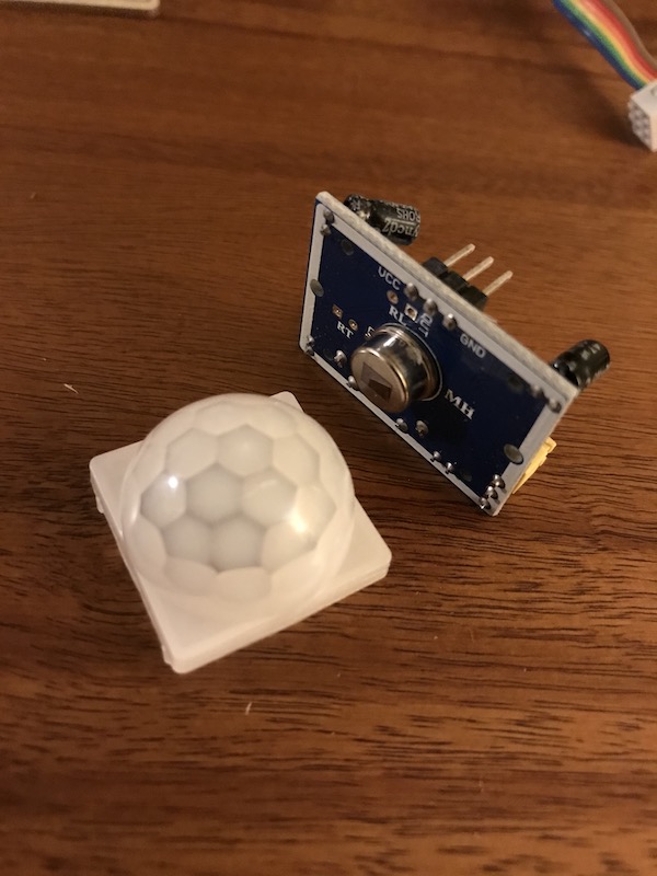
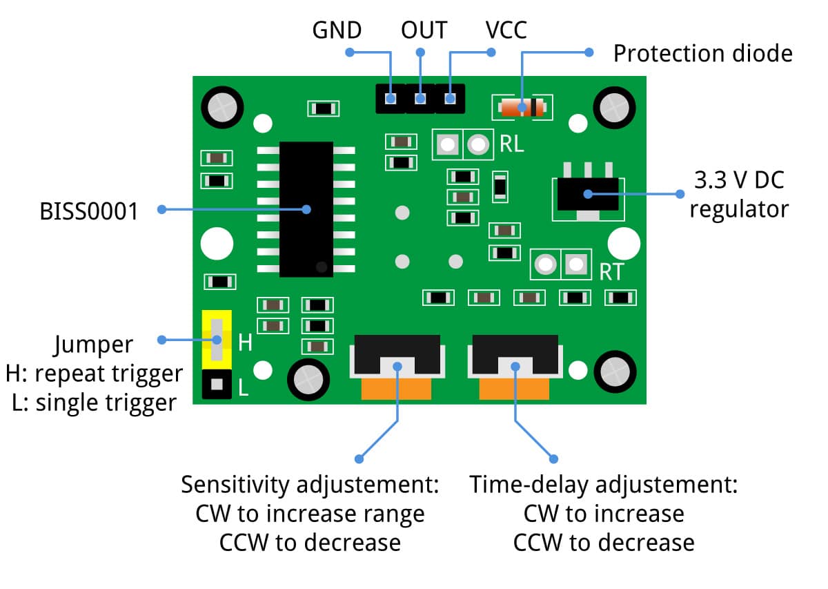
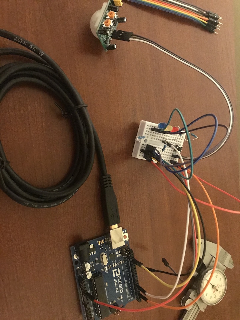
First I wired up the 3 wires going to the sensor. Besides ground and VCC there is only a single pin the outputs a high pulse when motion is detected. The IC on the sensor, BISS0001, processes the data from the sensor and formulates it into an output. All of the tuning for the sensor is done with jumpers and potentiometers on the sensor board. There is also the option to add two components to further customize the sensor. One of these is a thermistor to make it less sensitive to the ambient temperature, and one is a photoresistor which only allows the board to function when it is in a dark environment. I’m assuming these components could be placed on a breakout further from the sensor if the package required it. It’s interesting to learn more about how this seemingly simple and commoditized board is designed to be as customizable as it is.
With the board wired to the correct pins. I can now upload some test code. interestingly simply connecting a LED between the sensor output and ground is sufficient to test the sensor. However I wanted to get a sensor working across a serial connection to be used for my applications and interface week. With some modification I hope that this code will work for that application.
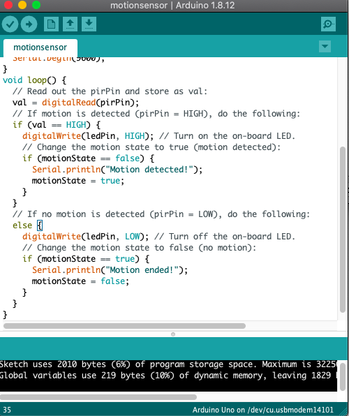
The example code is pretty simple and worked with minimal modification. I changed the LED to be the internal LED pin on the board. Once the serial connection begins. One interesting thing is there aren’t any wait lines in the main loop of the code. However when observing the sensor working it does ‘wait’. There are tools for adjusting this onboard the sensor breakout, however it would be nice to be able to tune this in the code.
/* Example code for HC-SR501 PIR motion sensor with Arduino. More info: www.makerguides.com */
// Define connection pins:
#define pirPin 2
#define ledPin LED_PIN
// Create variables:
int val = 0;
bool motionState = false; // We start with no motion detected.
void setup() {
  // Configure the pins as input or output:
  pinMode(ledPin, OUTPUT);
  pinMode(pirPin, INPUT);
  // Begin serial communication at a baud rate of 9600:
  Serial.begin(9600);
}
void loop() {
  // Read out the pirPin and store as val:
  val = digitalRead(pirPin);
  // If motion is detected (pirPin = HIGH), do the following:
  if (val == HIGH) {
    digitalWrite(ledPin, HIGH); // Turn on the on-board LED.
    // Change the motion state to true (motion detected):
    if (motionState == false) {
      Serial.println("Motion detected!");
      motionState = true;
    }
  }
  // If no motion is detected (pirPin = LOW), do the following:
  else {
    digitalWrite(ledPin, LOW); // Turn off the on-board LED.
    // Change the motion state to false (no motion):
    if (motionState == true) {
      Serial.println("Motion ended!");
      motionState = false;
    }
  }
}
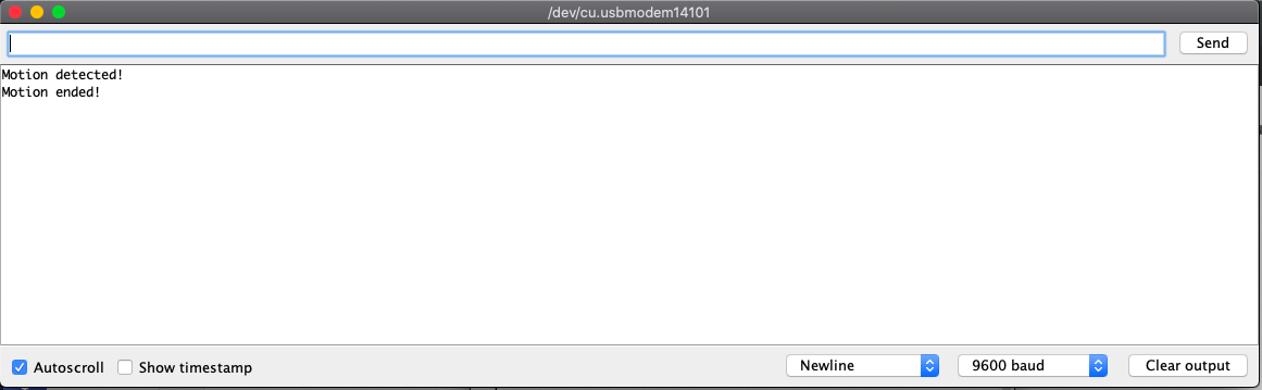
It works! I can see the sensor reading in the serial monitor. I want to modify this code to allow it to print the time out. After reading it seems like this will be challenging to do with only the arduino since there is no simple time library without adding a RTC component. However time stamps can be added on the serial monitor and there are opportunities for incorporating this feature into a GUI.
Group Assignment
I hooked up my sensor board to a variable power supply and the Lab oscilloscope. When triggering the sensor I could see the power spike.
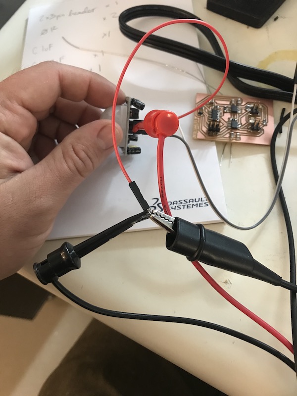
See video!
Additional input work
I used a rotary encoder in my final project