5. Electronics production
Flex PCBs Created on Fiber/CO2 Laser
I have always been interested in less conventional PCB fabrication techniques. When one of my students expressed interest in using flex PCBs in her final project I started doing some research in alternative methods to suggest besides the vinyl cutter. I have always heard mixed reviews of vinyl cut circuits, it seems like the fussy and nonlinear nature of the work often discourages students from pursuing it.
I found an excellent paper from Mannu Lambrichts et al from Hasselt University. Mannu was kind enough to share his paper with me. The work presented is extremely exciting, they used copper tape and Kapton to create multi layered flex pcbs through a multi step process.
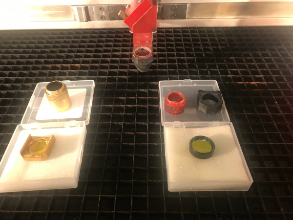
Setting up the flexx lens that allows for combination of Co2 and Fiber cutting
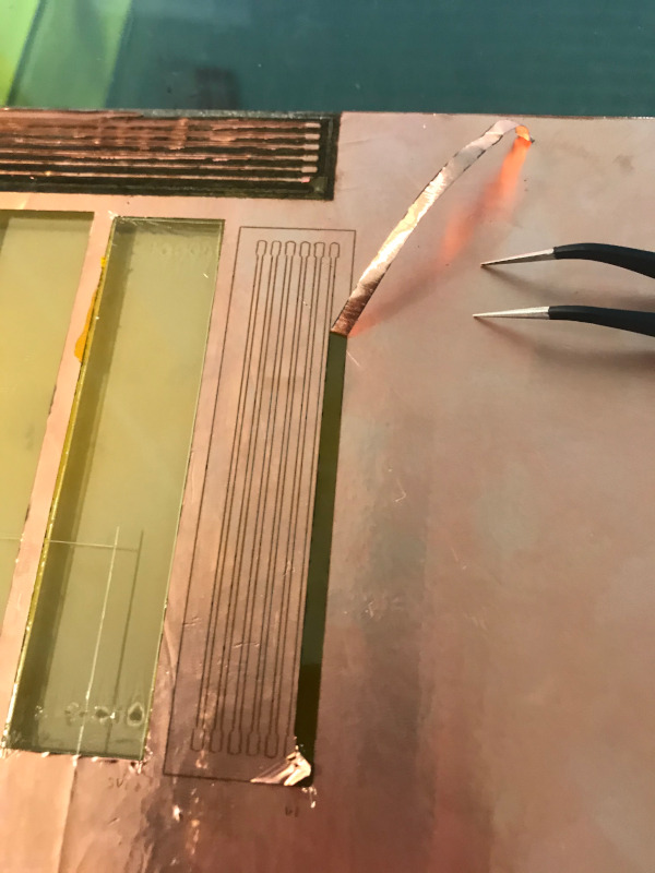
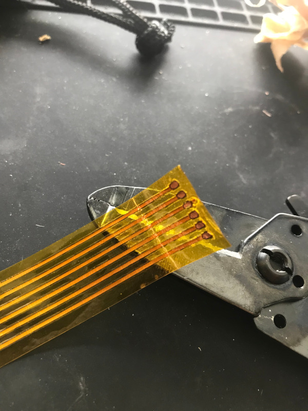
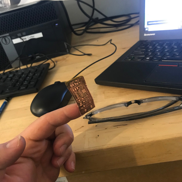
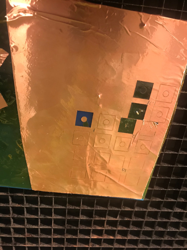
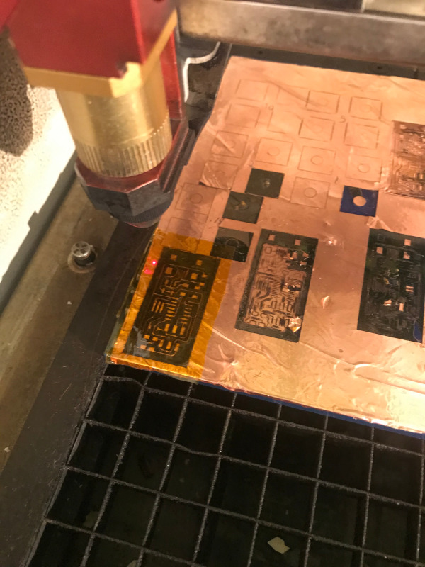
I first cut a test shape to calibrate the fiber laser to cut only through the copper tape and not the kapton.
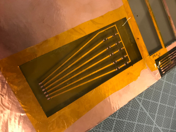
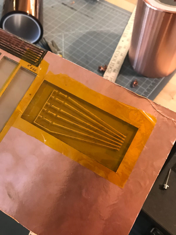
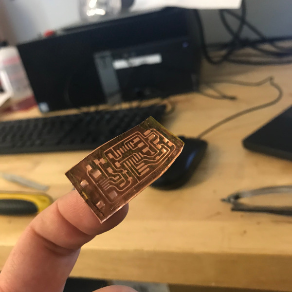
I started by laying a sheet of kapton tape on a square piece of acrylic and covering with 3M copper tape. It’s important to be able to take the piece in and out of the laser while maintaining perfect registration. I then cut the traces with the fiber laser, weed the negative space, and cover with another layer of kapton.
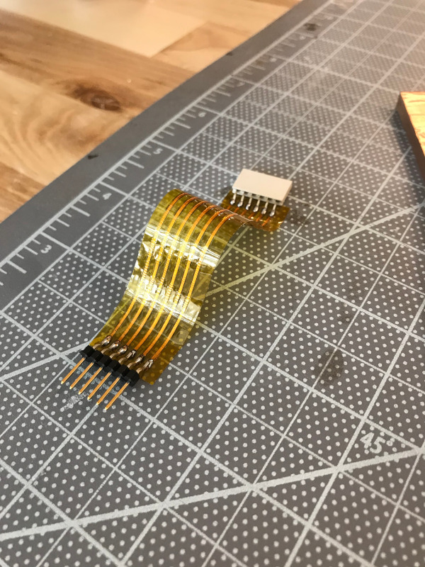
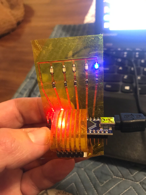
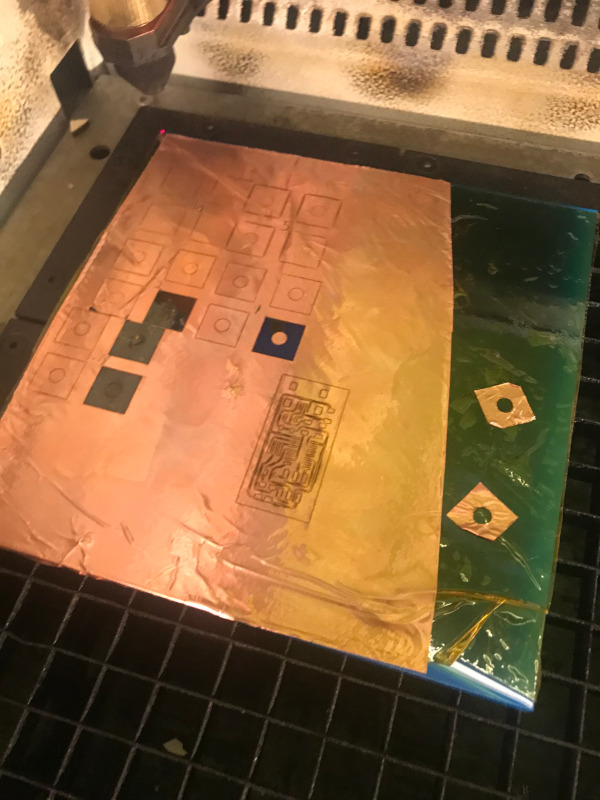 I can then use the Co2 laser to cut the pads out of the Kapton to create a soldering mask.
More testing to follow!
Fiber Laser Setup
Note: make sure you have plenty of time to setup, run, clean up, and restore the default machine settings before using the fiber laser.
Machine Prep-
-
Set up Flexx lens according to images and video. clean lens if needed and make sure not to touch glass with finger
-
Set lens type in the trotec controller (important to remember to change this back after use)
-
zero to the PCB using the brass knob focusing gauge
File Prep-
import PNG into illustrator
vector trace and expand
Draw cut lines in red (make sure it overlaps with engraved area or it wont cut)
file/print
under print settings change export to 1000dpi
save settings and print to driver
Cut/engrave
for settings use Dassault/Fab Academy/FR1 PCB (don’t change this setting please)
the job will raster cut then change focus and cut with the co2 laser
Flex Pcb
Same machine setups as above Material prep: 1. layer kapton onto acrylic sheet with at least one perfectly square edge 2. layer over 3M copper foil tape (only use copper tape from the lab supply) 3. place into corner of laser bed to insure repeatable alignment
vector trace and expand, no infill, cut lines red .001” line weight
for kapton mask layer must be on copper pads cut lines green .001” line weight
first cut use the settings Dassault/fab Academy/FlexPCBtesting remove pcb plate remove scrap copper and lay kapton over it re-register plate to laser second cut use settings Dassault/fab Academy/kaptonmaskcuttest
Remove scrap kapton
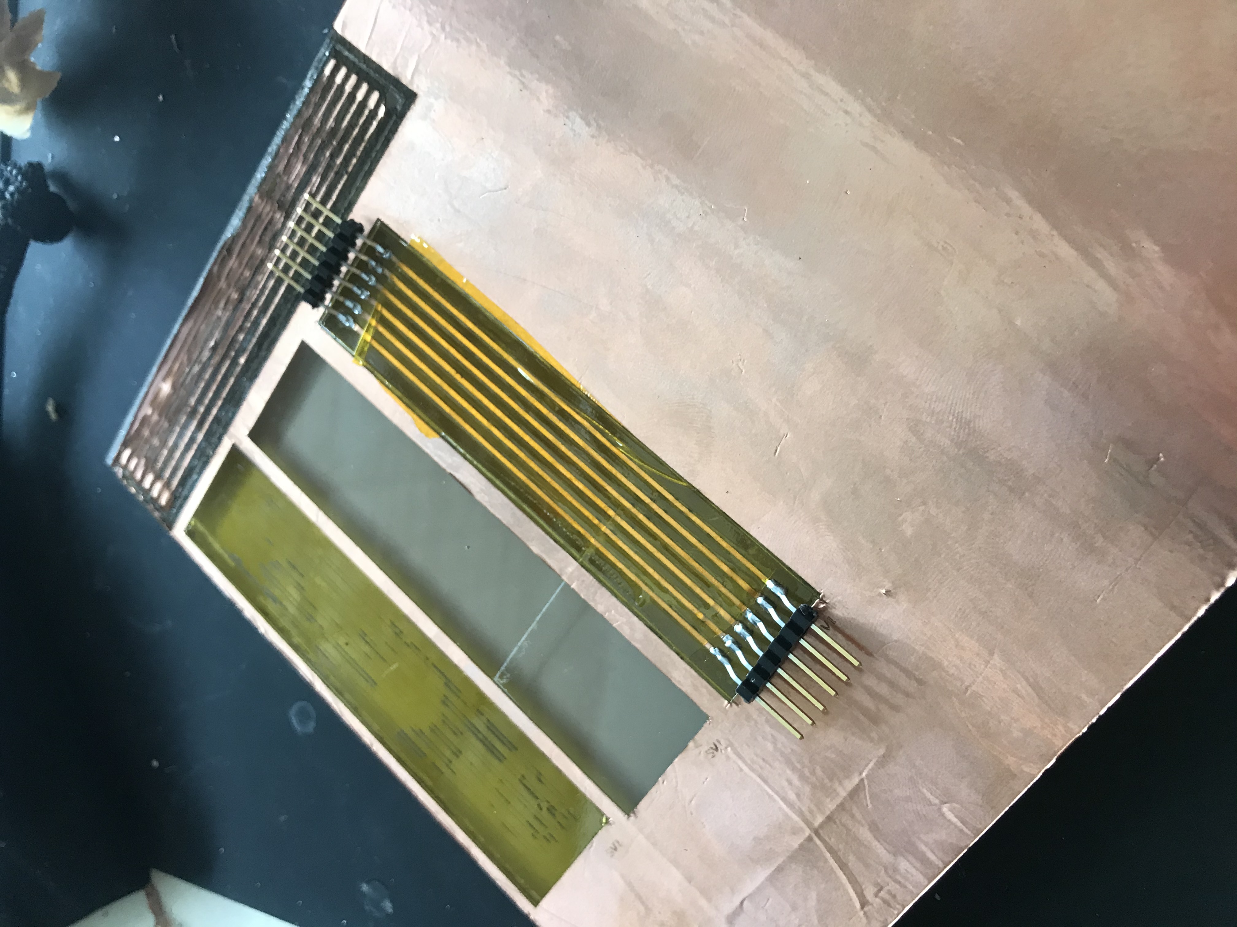
Fiber Laser Flex PCB Example file 1
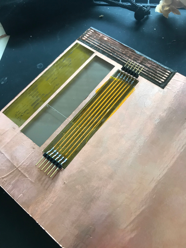
Fiber Laser Flex PCB Example file 2
PCB time!
after a few weeks where i was feeling relatively familiar with the material it’s time to really get out of my comfort zone! I have very little background in circuit design so this is really exciting.
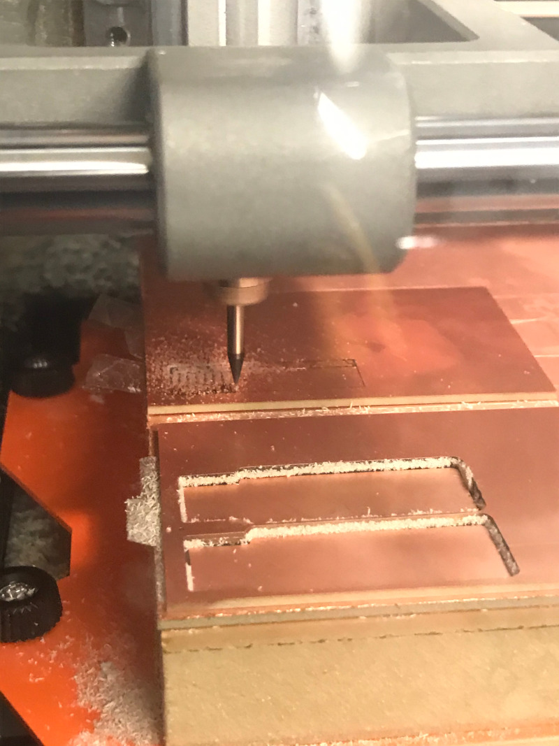
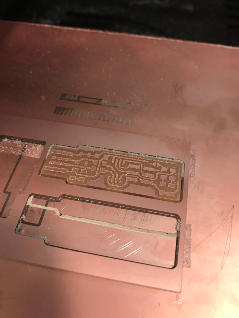
calibration cuts
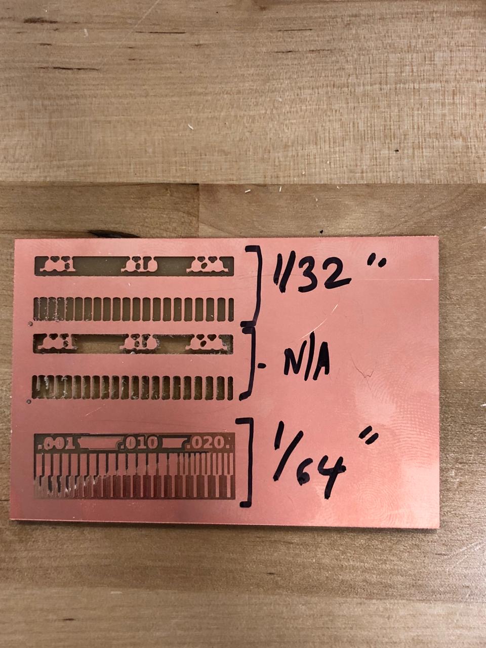
As a group we ran through some calibration cuts. We had some issues in these cuts that can be clearly seen in these images. The top cut (1/32) has very little resolution as the bit was unable to get into the profiles of many of the elements of the design. The second test cut down (NA) was cut using the mods preset for the 1/32 bit which through cut the board. The final (1/64) test cut has visible resolution for the cut and was a useful test. However due to the z height not being set low enough to compensate for the board being out of level, there is still copper remaining on the right hand side of the test cut.
I started by picking an in circuit programmer to make. I liked Brian’s documentation for building the FabTinyISP. It makes a lot of sense to jump right into the manufacturing step of this process, but it’s funny sticking one of these together on without much understanding of how they work.
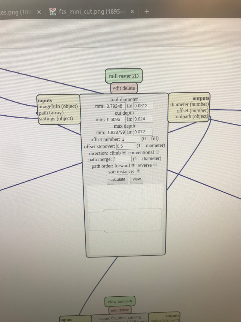
Milling the board
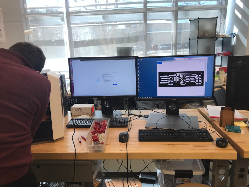
it was initially tricky to get the mill working correctly with mods. Since we started working off a windows computer we didn’t have the driver for running the mill directly from mods. We found a really great tutorial with a workaround for creating tool paths by adding a save function to mods. We then open and ran the file from the controller. Figuring out zeroing was also tricky, but we ended up getting it working by zeroing the machine coordinates.
our first attempt was using a tool that was too large, it milled but the traces were connected.
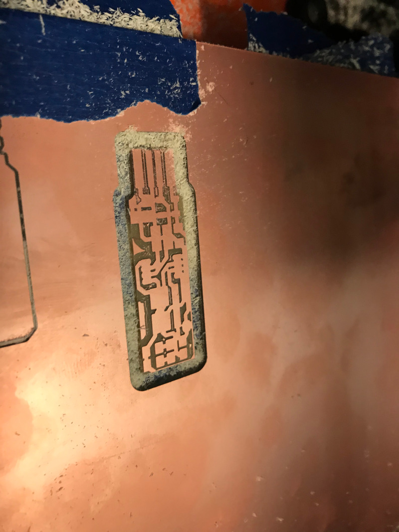
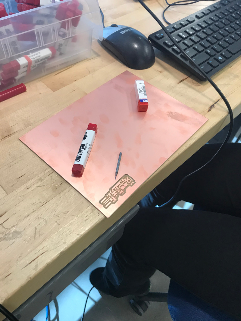
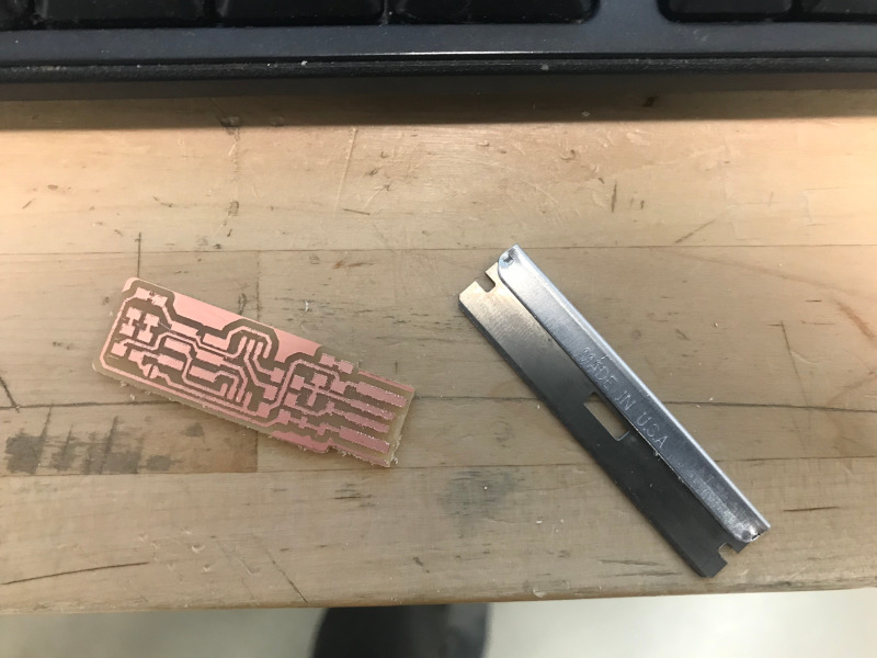
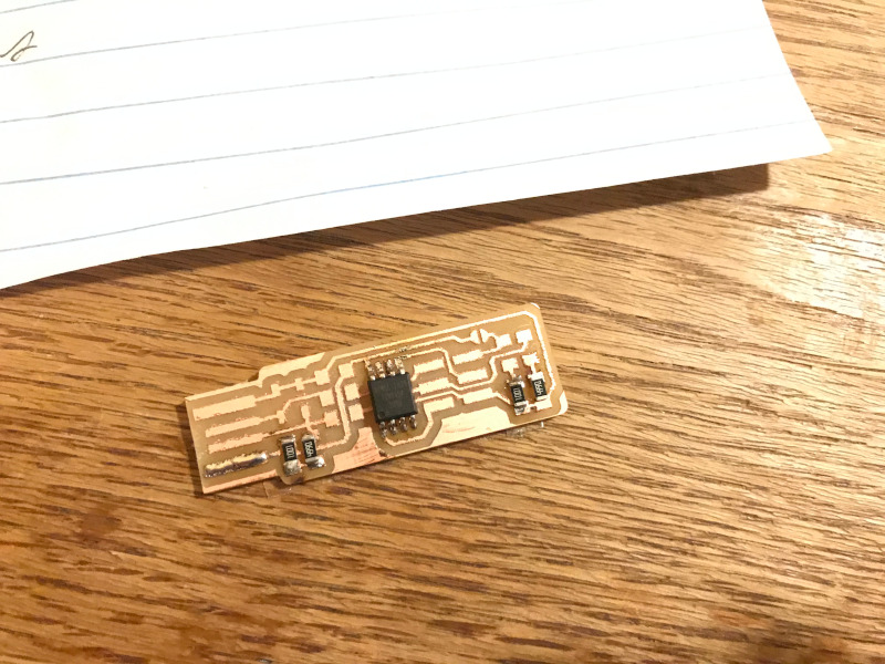
By the time i made my own board the mills were cutting a little bit rough! I deburred them with a razor blade which worked ok, but i’m still wondering if it’s worth redoing this board. Our instructor Greg told me that this is likely the result of a dull bit that should be replaced.
Soldering and stuffing
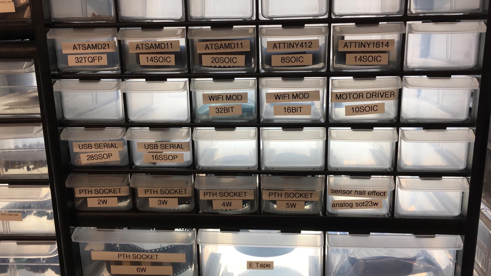
After the board is cleaned I picked the various parts to stuff the board. Despite some confusion with units everything seemed to be pretty straight forward. I’m still pretty amazed how small everything is.
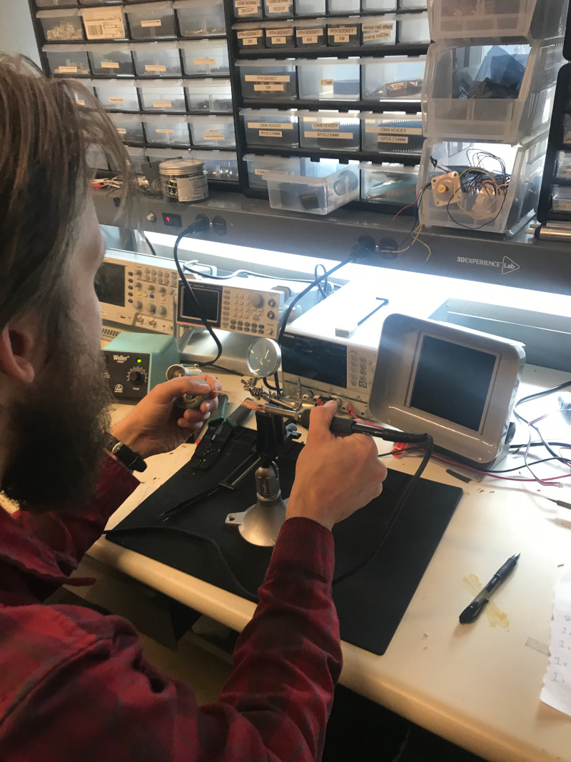
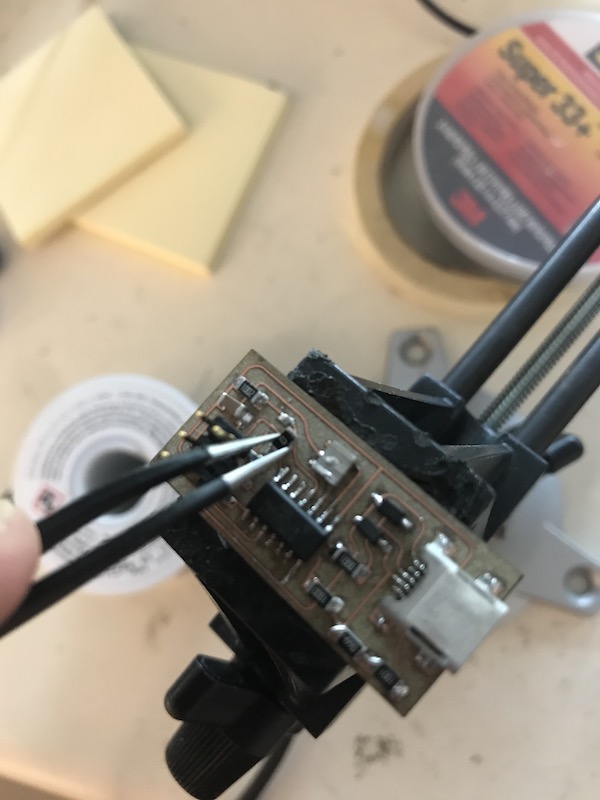
soldering things went pretty smoothly once i got the hand of it. I was using my iron at my shop which had a pretty large tip on it. interestingly one of the trickiest parts to do was the temporary solder bridge. This goes to show how it can be tricky to get things to short over the base of the PCB.
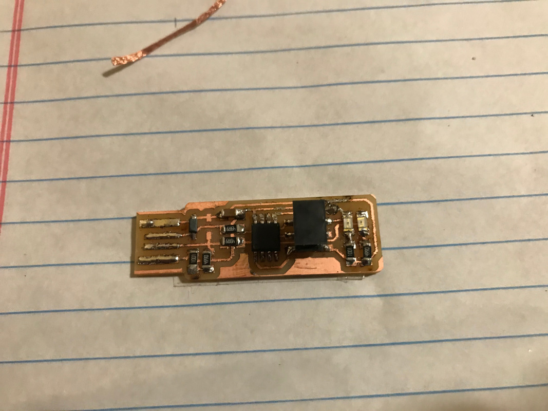
Looks alright! Now to program it.
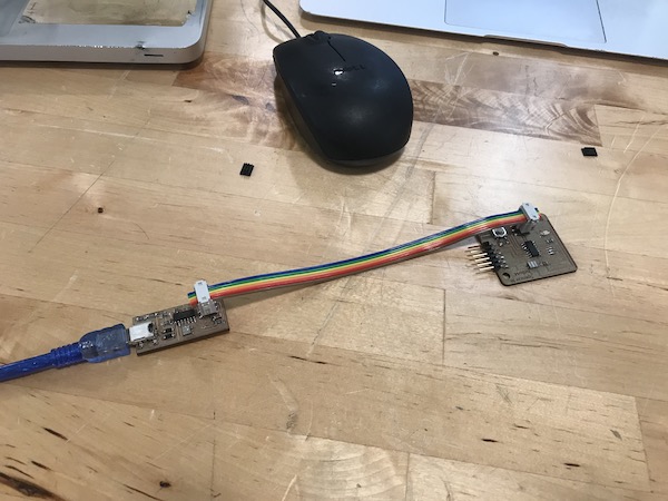
Testing the attinyICP
After spending some time working with and having some issues with programming my programmer my instructor suggested that I try the fabISP with an attiny44. I found very clear documentation for both fabricating and programming the board. I used an older mac and a commercial AVR for programming! It worked! and it programmed another target board!
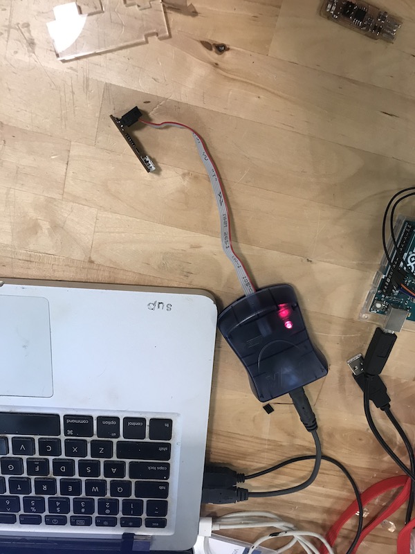
See week 9 for more information on my struggles with programing boards with macs