10. Molding and casting
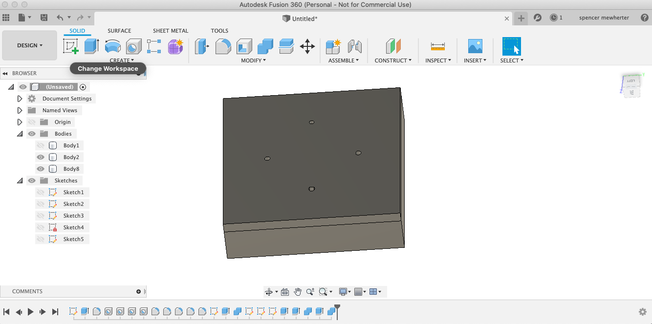
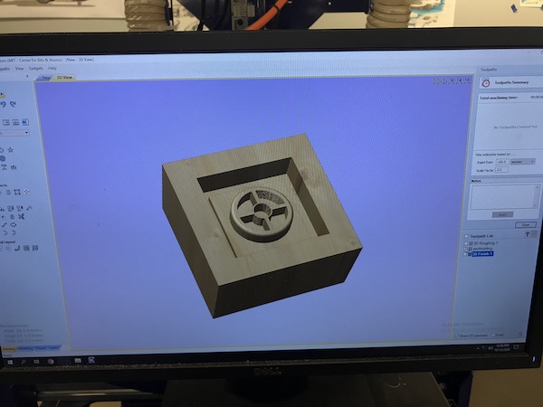
For this weeks assignment I was interested in making a plumbet, it is a plumb bob that can be sighted downward to line with a layout line. this is used in scribe rule timberframing. I started with a simple design in fusion 360. I then added vents and fill spouts. this was a good lesson in using the combine function in fusion and thinking through the casting workflow. One issue with the design is that the small holes through the inner ring won’t allow for the mold releasing. one option is to place the parting line along that plane. however this will still be problematic to mill. I kept it in the drawing since I would like to be able to do an investment cast of this design sometime. The final material for this will be cerrotru cast into a silicone mold.
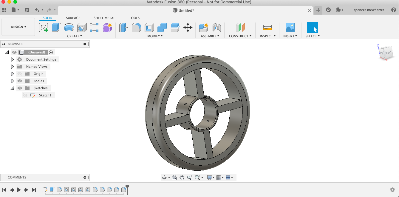
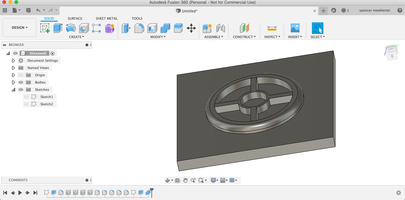
Here is the initial model for the plumbet
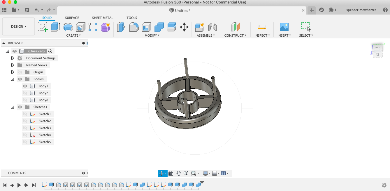
 The model with fill sprues added
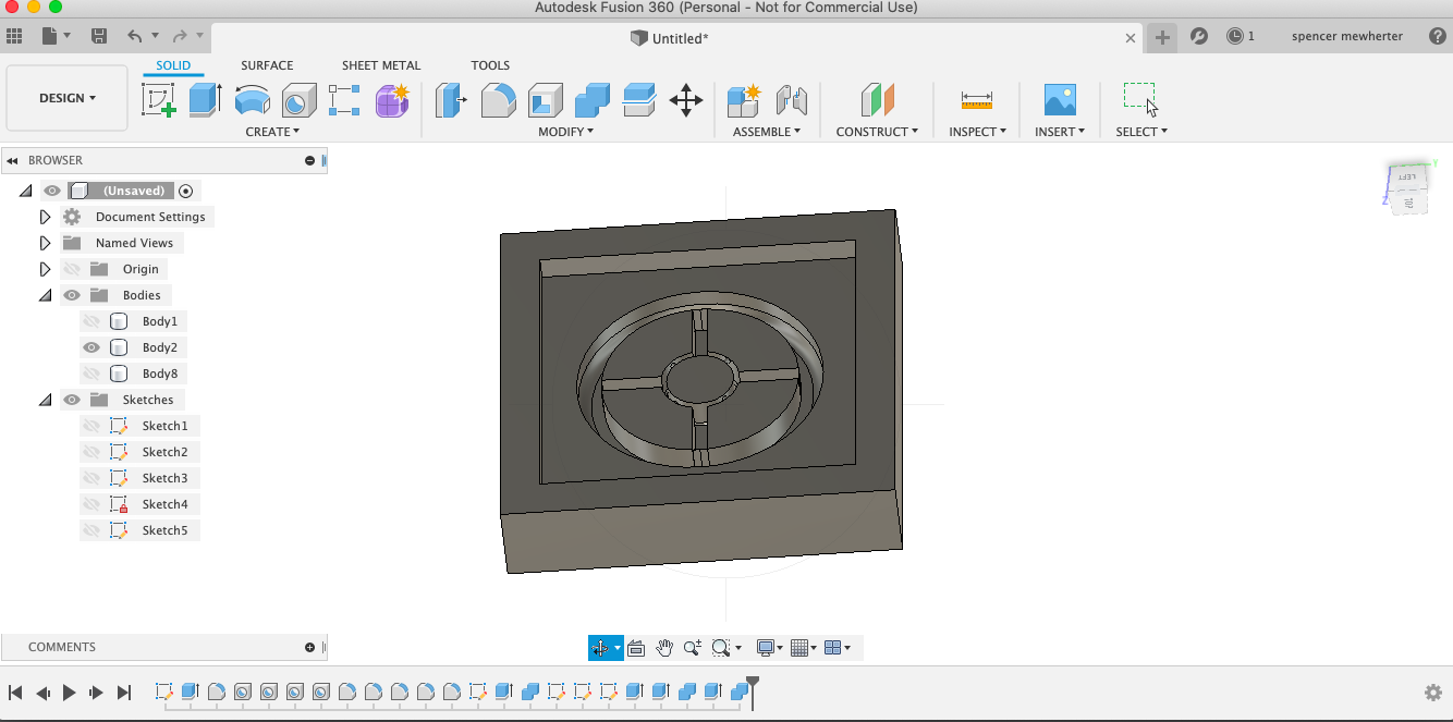
 Mold bottom
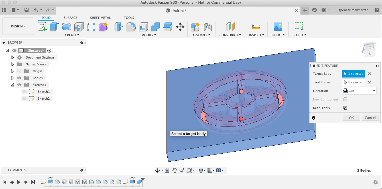
 Using Boolean functions to cut model into the mold
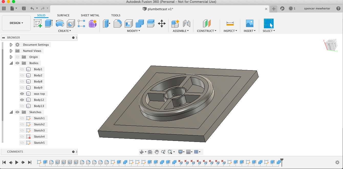
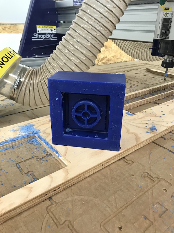
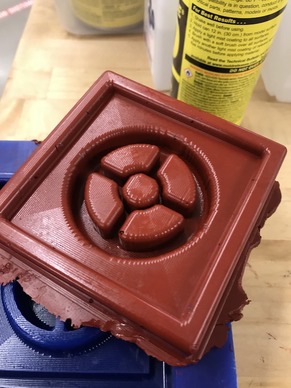
 Completed mold fit together
 milled wax mold top
 Milled wax mold bottom
Back in the lab! I decided to do these cuts on the shopbot. I’m curious how well it will machine on a machine like this, also I’m unable to get the necessary tool depth with the roland and the endmills available. I’m using Vcarve for my toolpath generation. Firstly I setup my work area to the size of the material. Typically when doing 2.5d machining I set it to the entire size of the work bed. I then import the STL file that I exported from fusion. The import process is somewhat fussy I find that the graphical interface is clearer then the descriptions. Here are my final import parameters.
importantly I check my scale against my fusion drawing. Then I draw a vector box the size of my material adding dogbone fillets. This is for a work holding pocket that I will cut first. Since all my files are aligned to the center this is a simple process. I then created my 3 tool paths.
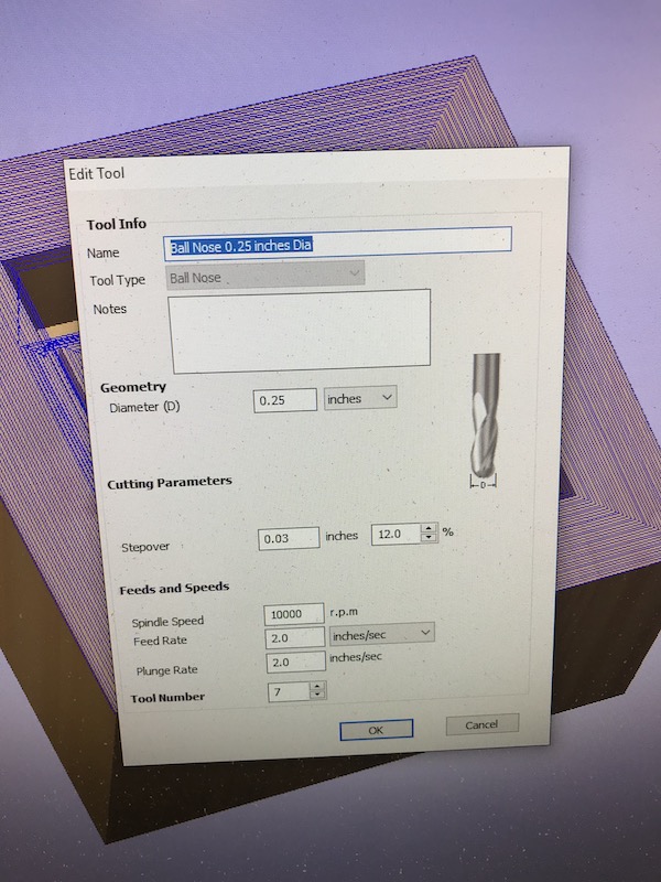
First is my work holding tool path, this is my 3d vector line inside cutout. I avoided using tabs by carefully locating a screw into the waste section of the cutout. I make a mistake with making this tool path initially, cutting on the outside of the line. I caught it after my first pass. so it’s salvageable, might even make it easier to remove. Second, I create a 3d roughing tool path for a .25” upcut endmill. My feeds and speeds are 2.0 IPS on both feed and plunge and 10000 RPM.
After warming up the spindle I’m ready to cut.
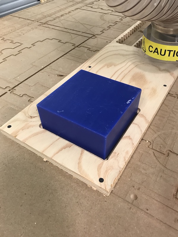
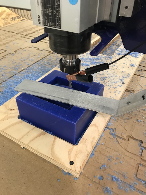
Cutting out work holding pocket, the block is fixtured with double sided carpet tape.
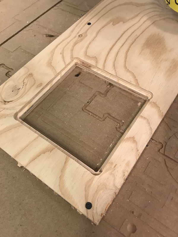
The tool is rezeroed to the top of the material. The XY origin remains the same, I then run the roughing tool path with a .25 end mill. I follow the tool with a shopvac to minimize the amount of chips generated. I didn’t want to use the dust collector since it might catch on the edge of the block.

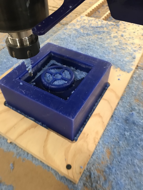
I then run the finishing pass after rezeroing the tool with the .25 ball nose mill. This is a relatively quick tool path.
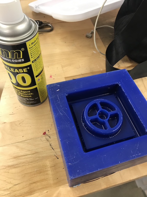
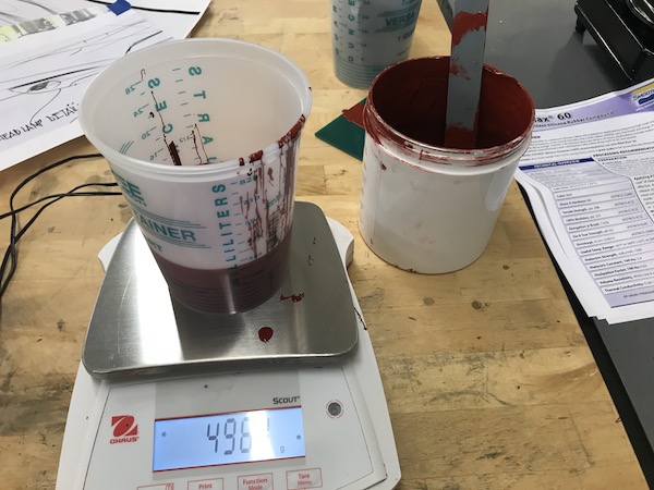
Looks good time to mix the silicone! After reading the SDS I get ready to mix the mold max 60. First I apply two coats of release agent, brushing the first in, then overspaying.
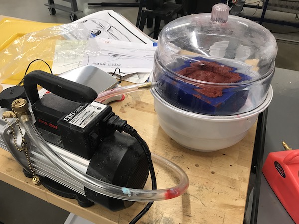
While that cures I mix a 100 : 3 ratio by weight of part A and part B. I mix both parts separately before mixing them for 3 minutes . I then degassing the mix in the vacuums chamber for 3 minutes, It expands a lot! I
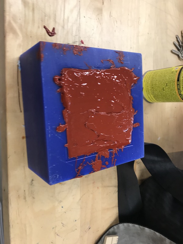
then pour it into the mold, then put it back into the vacuum chamber. it expands quite a bit. I cycle the vac pump and it settles, unfortunately My bottom surface has sunk a lot. Next time I should give myself more space for overfilling.
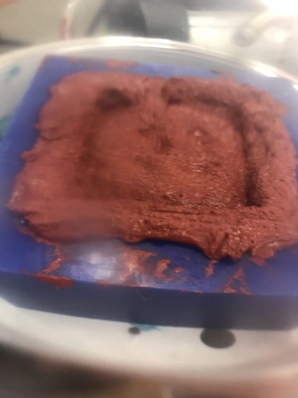
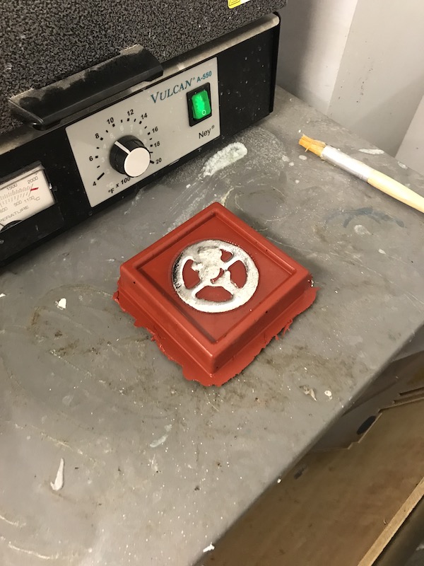
After curing it pops out just fine. Overall I’m really happy with my surface finish. There are only one or two air bubbles left, which I can deal with.
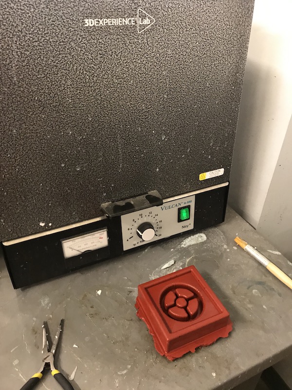
I then start melting my cerrotru in the oven. I make sure to have everything in place before I start this process.
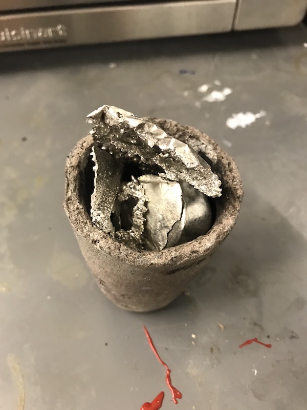
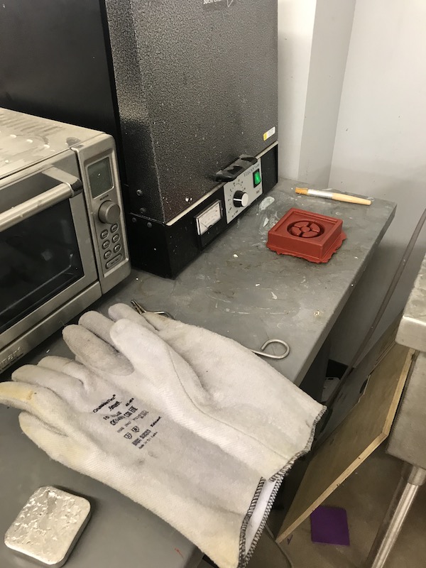
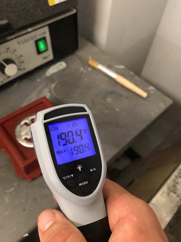
I coat the mould with quick releases 200 Once the metal is molten I carefully pour in into the mold. I check the temperature throughout this process with an IR thermometer.
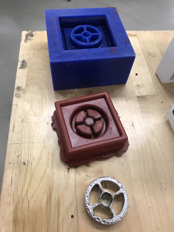
Once it has cooled I demolded it. I wasn’t super happy with the surface finish, but It’s a good starting point for future work.
Design Files
Group Assignment
Reviewing Safety Data Sheet. There are two different sheets for part A and part B, interestingly both of these sheets covers a large selection of the product line. I’m assuming that the core ingredients are the same across many different products.
For Mold Max series part A there are no listed hazards. It does give treatment options for skin and eye contact and ingestion
For Mold Max Series part B it’s a lot more dangerous! The SDS lists hazards for skin, eye and inhalation. Importantly, it recommends to mix outside or in a well ventilated area while wearing appropriate PPE.
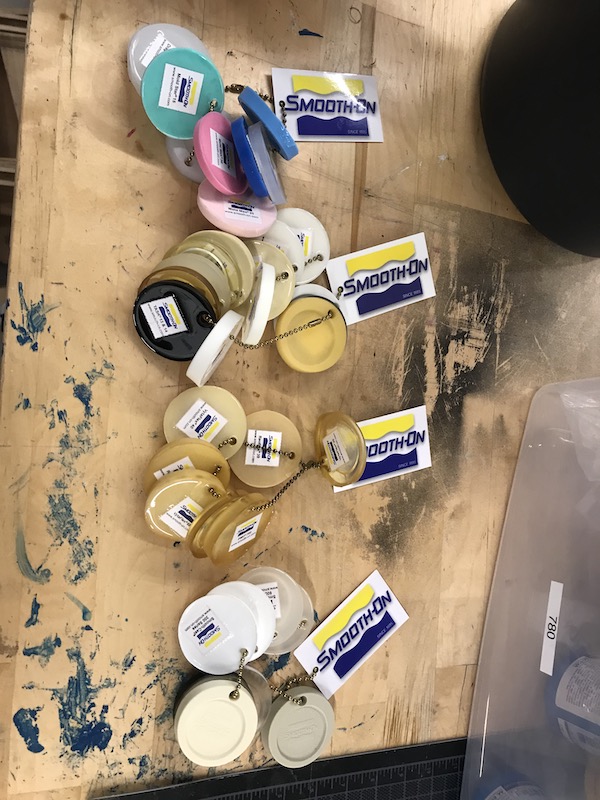
There is a great selection of precast samples in the shop.