17. Machine design
Group project
The group project is documented here

Motor Control
The GUI with communicate with the IC using pyserial. The control scheme depends on which motor we end up using
Stepper motor control
Since we all have access to arduinos and a stepper motor from our kits I thought it would be a good idea to base the motor control off of that. for the final motor control we will need to use larger independently powered motors. The advantage of using stepper motors is high positional accuracy built in without any other systems. The major disadvantage is high cost and power consumption.
DC motor control with PID
one option is to close the loop and use a dc motor with a pid control to position it. I found some helpful code that was helpful to understanding the control scheme. the primary advantages for this would be lower cost, faster speed, and potentially increased accuracy. The primary disadvantages would be the increased complexity of a hall effect sensor and magnets along the ring.
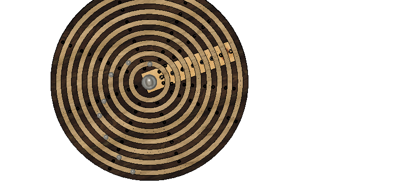
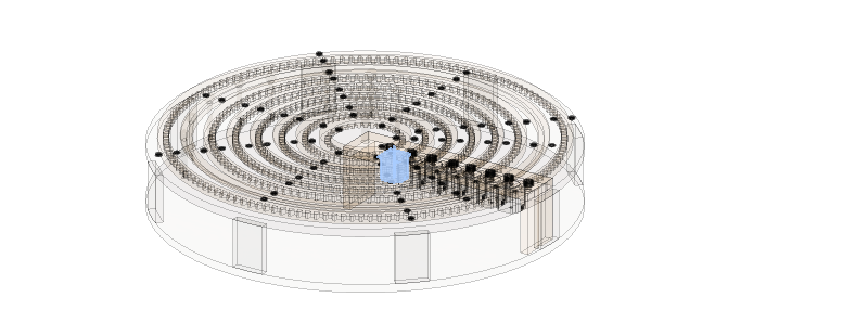
Gantry and Frame
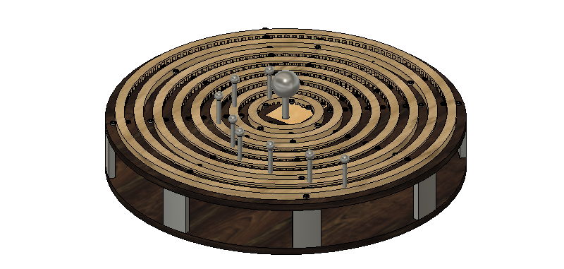
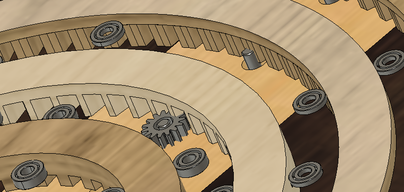
the gantry design was done in fusion 360. The frame will be cut out of two sheets of 3/4 nominal plywood. The gear teeth for the internal gears will need to be cut with a 1/4 inch bit. for generating the gears I used this script to generate the gears, with some modification after the fact. This had some issues and though I was able to adapt it to the drawing it was less than idea. The online Gear Generator was what I was working in initially. However they charge 2$ to export an SVG!! though this isn’t a ton of money, I was grumpy that it wasn’t clear that you needed to pay to export, and we can’t be paying for svgs!
the motors are drawn as NEMA 23 stepper motors, ideally in the final project we will adapt it to use fewer motors with a gear box between them.
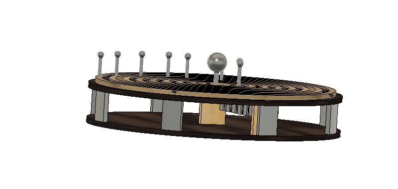
the bearings along the frame hold the rings in position along the side. Experiments are needed to see what is needed for a bushing along the bottom. I hope that a simple low friction hdpe block will allow for easy movement. Another option is to add ball bearings to make the rings into large roller bearings.
Additional Work
As mentioned in the group documentation, we were not able to build this machine as a group. However my Final Project gives documentation of me designing, building, and running a machine.